
Summary of Contents for WMH Tool Group JET JWBS-18X
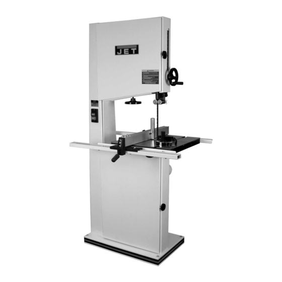
- Page 1 Operating Instructions and Parts Manual 18” Band Saw Model JWBS-18X WMH TOOL GROUP 2420 Vantage Drive Elgin, Illinois 60123 Part No. M-710750 Ph.: 800-274-6848 Revision A 3/04 www.wmhtoolgroup.com Copyright © WMH Tool Group...
-
Page 2: Warranty And Service
Warranty and Service WMH Tool Group warrants every product it sells. If one of our tools needs service or repair, one of our Authorized Repair Stations located throughout the United States can provide quick service or information. -
Page 3: Table Of Contents
Table of Contents Warranty and Service ..........................2 Warning..............................4 Introduction..............................6 Specifications ............................6 Grounding Instructions..........................7 115 Volt Operation ..........................7 230 Volt Operation ..........................8 Unpacking ...............................9 Contents of Shipping Container ......................9 Assembly and Setup..........................10 Upper Bearing Guide Adjustment .......................10 Lower Bearing Guide Adjustment .......................11 Mounting the Table..........................11 Adjusting 90 Degree Table Stop ......................12 Rail Assembly ............................12... -
Page 4: Warning
Warning 1. Read and understand the entire owners manual before attempting assembly or operation. 2. Read and understand the warnings posted on the machine and in this manual. Failure to comply with all of these warnings may cause serious injury. 3. - Page 5 blahblahblah 20. Make your workshop child proof with padlocks, master switches or by removing starter keys. 21. Give your work undivided attention. Looking around, carrying on a conversation and “horse-play” are careless acts that can result in serious injury. 22. Maintain a balanced stance at all times so that you do not fall or lean against the blade or other moving parts.
-
Page 6: Introduction
Shipping Weight (approx.) (lbs.) ......................407 The above specifications were current at the time this manual was published, but because of our policy of continuous improvement, WMH Tool Group reserves the right to change specifications at any time and without prior notice, without incurring obligations. -
Page 7: Grounding Instructions
Grounding Instructions This machine must be grounded while in use to protect the operator from electric shock. In the event of a malfunction or breakdown, grounding provides a path of least resistance for electric current to reduce the risk of electric shock. This tool is equipped with an electric cord having an equipment-grounding conductor and a grounding plug. -
Page 8: 230 Volt Operation
230 Volt Operation If 230V, single phase operation is desired, the following instructions must be followed: 1. Disconnect the machine from the power source. 2. This bandsaw is supplied with four motor leads that are connected for 115V operation, as shown in Figure A. -
Page 9: Unpacking
Unpacking Contents of Shipping Container Bandsaw Table Fence and Rail Assembly Resaw Guide and Knob Miter Gauge Owner’s Manual Warranty Card Accessory Package Contains: Hardware Bag 2 Knobs 1 Hex Wrench 1 Handle 1 10/12mm Wrench Fence Hardware Bag 4 Hex Cap Screws 4 Flat Washers 4 Lock Washers Rail Hardware Bag... -
Page 10: Assembly And Setup
Assembly and Setup 1. Attach the handle (A, Figure 1) to the handwheel (B, Figure 1). 2. Turn blade tension handwheel (C, Figure 1) counterclockwise to tension blade and clockwise to loosen the tension. A gauge on the upper wheel slide bracket (D, Figure indicates approximate tension... -
Page 11: Lower Bearing Guide Adjustment
Lower Bearing Guide Adjustment Disconnect machine from power source (unplug) before making any adjustments! Blade teeth are sharp - use care when working near the saw blade. Failure to comply may cause serious injury. 1. Blade tension must be properly adjusted prior to bearing guide setup. -
Page 12: Adjusting 90 Degree Table Stop
Adjusting 90 Degree Table Stop 1. Blade tension must be properly adjusted prior to adjusting 90 degree stop, see “Adjusting Blade Tension” on page 16. 2. Loosen lock knobs (A, Figure 7) and tilt table until it rests against table stop bolt (B, Figure 7). -
Page 13: Fence Assembly And Adjustment
Fence Assembly and Adjustment 1. Attach the fence (A, Figure 10) to the fence body (B, Figure 10) with four 5/16” x 3/4” hex cap screws, four 5/16” lock washers, and four 5/16” flat washers. 2. Thread a hex nut (D, Figure 11) onto the pad’s threaded stud (E, Figure 11) and insert through the fence and rear hook (F, Figure 11). -
Page 14: Resaw Guide
Resaw Guide For resawing attach the post (A, Figure 13) to fence with the lock knob (B, Figure 13). There is slotted hole fence that will accommodate the resaw kit. Position the post so that it is centered with the front edge of the blade. -
Page 15: Changing Blades
Changing Blades Disconnect machine from power source. Blade teeth are sharp, use care when handling the blade. Failure to comply may cause serious injury. 1. Disconnect machine from power source. 2. Remove the table insert (A, Figure 16), and table pin (B, Figure 16). 3. -
Page 16: Adjusting Blade Tension
Adjusting Blade Tension 1. Disconnect machine from power source. 2. Turn blade tension handwheel (A, Figure 18) counterclockwise to tension blade, and clockwise to loosen the tension. A gauge on the upper wheel slide bracket (B, Figure 18) indicates the approximate tension according to the width of the blade. -
Page 17: Replacing V-Belt
Replacing V-Belt 1. Disconnect machine from power source. 2. Release blade tension by turning blade tension handwheel clockwise. 3. Release belt tension by loosening the two hex cap screws (A, Figure 19, the pivot bolt is not shown in the photo). Raise the motor and place a block of wood under the motor to take the tension off the belt. -
Page 18: Electrical Connections
Electrical Connections All electrical connections must be done by a qualified electrician. Failure to comply may result in loss of property and/or serious injury. JWBS-18X is rated at 1.75 HP, 1Ph, 115/230V, prewired 115V. The bandsaw comes with a 115V plug (A, Fig. 22). - Page 19 Width Band saw blades come in different standard widths, measured from the back of the blade to the tip of the tooth. Generally, wider blades are used for ripping or making straight cuts; narrower blades are often used when the part being cut has curves with small radii.
-
Page 20: Blade Breakage
Because of the importance of blade selection, it Maintenance is recommended that you use the blade selection guide on page 21. Before any intervention on When cutting, the machine, disconnect it from the electrical overfeed the blade; overfeeding will reduce supply by pulling out the plug. -
Page 21: Blade Selection Guide
Blade Selection Guide Identify the material and thickness of your workpiece. The chart will show the recommended PITCH, blade TYPE, and FEED RATE. Key: L – Low H – Hook M – Medium S – Skip H – High R – Regular Example: 10/H/M means 10 teeth per inch / Hook Type Blade / Medium Feed Study the part drawing or prototype, or actually measure the smallest cutting radius required,... - Page 22 Troubleshooting Trouble Probable Cause Remedy Saw unplugged Check plug connections Saw stops or will not Fuse blown, or circuit breaker tripped Replace fuse, or reset circuit breaker start Cord damaged Replace cord Check blade with square and adjust Stop not adjusted correctly stop [page 12] Does not make accurate 45...
-
Page 23: Optional Accessories: Band Saw Blades
Optional Accessories: Band Saw Blades Stock No. Material Length Width Thickness Type 710030 ..Carbon Steel..137”..1/4” ..0.025” ..Skip....6 710031 ..Carbon Steel..137”..3/8” ..0.025” ..Skip....4 710032 ..Carbon Steel..137”..1/2” ..0.025” ..Hook....3 710033 .. -
Page 24: Parts List: Upper Wheel Assembly
Parts List: Upper Wheel Assembly Index No. Part No. Description Size 1....JWBS18X-101..Saw Body ..................... 1 2....TS-0680031 .... Carriage Bolt..........5/16 x 5/8......6 3....JWBS18-103... Upper Wheel Bracket................2 4....TS-0680031 .... Flat Washer ..........5/16 ........6 5....TS-0720081 .... Lock Washer..........5/16 ........6 6....TS-0561021 .... -
Page 25: Upper Wheel Assembly
Upper Wheel Assembly... -
Page 26: Parts List: Lower Wheel And Motor Assembly
Parts List: Lower Wheel and Motor Assembly Index No. Part No. Description Size 1....JWBS18-201... Bearing Base ..................1 2....JWBS20-62..... Adjusting Bolt..................4 3....TS-0720091 .... Lock Washer..........3/8 ........4 4....TS-0060081 .... Hex Cap Screw..........3/8 x 1-3/4......4 5....BB-6204ZZ.... -
Page 27: Lower Wheel And Motor Assembly
Lower Wheel and Motor Assembly... -
Page 28: Parts List: Blade Guide Assembly
Parts List: Blade Guide Assembly Index No. Part No. Description Size 1....TS-0208061 .... Hex Cap Screw..........5/16 x 1......4 2....TS-0720081 .... Lock Washer..........5/16 ........4 3....TS-0680031 .... Flat Washer ..........5/16 ........8 4....JWBS18-304... Guide Bar Bracket ................1 5....JWBS18-305... -
Page 29: Blade Guide Assembly
Blade Guide Assembly... -
Page 30: Parts List: Table And Fence Assembly
Parts List: Table and Fence Assembly Index No. Part No. Description Size 1....JWBS18-401... Lock Knob .................... 1 2....TS-0680021 .... Flat Washer ..........1/4 ........11 3....JWBS18-403... Miter Gauge Body................. 1 4....JWBS20-156... Guide Disc.................... 1 5....JWBS18-405... Phillips Pan Head Machine Screw....M6 x 8....... 1 6....JWBS18-406... - Page 31 Table and Fence Assembly...
-
Page 32: Electrical Connections
Electrical Connections... - Page 33 NOTES...
- Page 34 NOTES...
- Page 35 NOTES...
- Page 36 WMH Tool Group 2420 Vantage Drive Elgin, Illinois 60123 Phone: 800-274-6848 www.wmhtoolgroup.com...
Need help?
Do you have a question about the JET JWBS-18X and is the answer not in the manual?
Questions and answers