Table of Contents
Advertisement
Quick Links
Advertisement
Table of Contents

Related Manuals for Decatur Electronics SVR3D

Summary of Contents for Decatur Electronics SVR3D
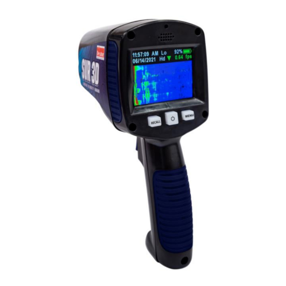
- Page 1 Surface Velocity Radar SVR3D User’s Manual Rev 10-6-21...
-
Page 2: Table Of Contents
Table of Contents Table of Contents About This Manual....................5 1. Safety Information ..................5 ....................5 WARNING ......................5 2. Receiving Inspection..................7 3. Getting Started ..................... 8 4. Components ....................13 RCL ......................13 PWR......................14 MENU ......................14 Clock Time Information ................ - Page 3 7. Angle Compensation ................. 32 8. Communications Port ................36 9. Performance Tips ..................37 10. Care, Cleaning, and Storage ..............43 11. Data download ................... 43 12. Specifications ..................... 49 a. Legal Requirements ................... 52 b. Frequently Asked Questions (FAQ) ............53 c.
- Page 4 The SVR3D incorporates many leading features such as cosine error correction for the vertical and horizontal angle positions of the gun to the target. The SVR3D also contains a configurable horizontal cosine adjustment that may be used when the angle of the gun is not parallel to the flow of the target.
-
Page 5: About This Manual
All service needs should be referred back to the manufacturer. • The internal battery pack is not user serviceable. WARNING Do not put the radar gun in the water. This will damage it. The SVR3D measures the water surface only from outside the water. - Page 6 Never submerge the device. If the SVR3D should accidentally get submerged, remove from the water immediately, wipe off and let dry. • Do not drop the SVR3D on hard surfaces since damage could occur. Units damaged by dropping or abuse are not covered for warranty repair.
-
Page 7: Receiving Inspection
Record the damage on the bill of lading and keep a record of the problems or damage. • The package should include the following pictured items along with this User’s Manual. SVR3D™ Detachable power and data USB cable... -
Page 8: Getting Started
3.1 Introduction The SVR3D is a hand-held surface velocity radar (SVR™) gun specifically designed to measure the surface velocity of water— great for use in streams and rivers. Features such as Recall allows you to review the previous measurement. Other features are selectable through the menu option. - Page 9 When you first receive your radar, the batteries will need to be charged for the first time before using. Once batteries have been charged if you do not use the SVR3D for 3-4 weeks, you will want to recharge the batteries before use in order to get the full run time .
- Page 10 3.3 Charging the Batteries The USB power cable that comes with the SVR3D is used to charge the internal battery. Plug the USB cable into the USB connector located near the front of the trigger. The USB connector can be inserted in either orientation. If the SVR3D is powered off and charging, a green charging status light will illuminate the center power button.
- Page 11 Figure 3.3c Battery and charging status while SVR3D is ON and charging • Best performance from your batteries is obtained when recharged at temperature between 50ºF (10ºC) and 113ºF (45ºC) . Recharging outside of that temperature range may result in reduced battery life or incomplete charging.
- Page 12 The USB cable plugged into the SVR3D provides power to charge the internal batteries and for serial communication. The USB port on the SVR3D is located on the housing just in front and to the side of the trigger switch. With the USB cable...
-
Page 13: Components
• A measurement is not currently taking place. The recall mode allows the operator to recall the last measured speeds that the SVR3D calculated. After pressing the RCL button, a list containing the 8 most recent measured speeds will be displayed with the most recent speed displayed at the bottom and 8 most recent at the top. -
Page 14: Pwr
The PWR button (center button) turns the radar on and off. When powered on the SVR3D will enter a power up cycle displaying a test screen, recalling the last saved operating parameters, placing the SVR3D radar into the last operating mode prior to being turned off and finally preparing the radar to take a measurement. - Page 15 (see LCD brightness menu settings) 4.2.2 SVR3D display after power on When first turned on, the SVR3D performs a display check to allow the user to verify proper screen function. Figure 4.1a 4.2.3 SVR3D Common display icons for all modes...
-
Page 16: Clock Time Information
SVR3D shows current AM or PM indicator. (If clock enabled and only applies if 12 hour mode is set) Low or High Speed operation SVR3D shows displays “Lo” if radar is set for Low Speed Operation. SVR3D shows displays “Hi” if radar is set for High Speed Operation. -
Page 17: Standard Deviation Value
4.2.4 If the SVR3D is set for digital speed display operation (digital display of instantaneous and averaged speeds), the screen will appear as such: Figure 4.2.4 Digital display operation with status indicator icons. Standard Deviation Value SVR3D shows the current standard deviation value. -
Page 18: Speed Direction Indicator
4.2.5 If the SVR3D is set for spectrum operation (Spectrum display), the screen will appear as such: Figure 4.2.5 Mode 1 Spectrum display with status indicator icons. Speed Direction Indicator SVR3D will show a direction indicator depending on the direction of the water flow. A downward pointing arrow (as shown) indicates the detected water flow is in the approaching direction. -
Page 19: Water Velocity Spectrum Display Area
Water Velocity Spectrum Display Area The SVR3D will show the spectrum of the water return by displaying all Doppler return frequencies from the water flow. The display shows increasing water velocities from left to right and increasing signal strengths from bottom to top. The signal strengths are color coded with blue being the weakest Doppler return with red color denoting a large return. -
Page 20: Speed Direction Indicator
Water Velocity Spectrogram Display Area The SVR3D will show the spectrogram display of the water return by displaying all Doppler return frequencies from the water flow over time. This display is similar to the spectrum display however, instead of the showing the signal strength in the vertical direction, the display now shows the spectrum over time in that direction. -
Page 21: Average Speed Value
Average Speed Value SVR3D shows the current averaged speed value. -
Page 22: Operating Modes
The MENU and SEL buttons on the SVR3D control panel lets you review and change settings. The radar gun will remember the settings you last set when it is turned off and will power up with them. - Page 23 Main Menu Settings: (use MENU key to cycle through) (1) MODE (use trigger switch to move through settings) a. Sub-menu Settings: i. Approach only ii. Recede only iii. All Approach Recede (2) SENSITIVITY (use trigger switch to move through settings) a.
- Page 24 Min Sens Max Sens (3) DISPLAY MODES digital display mode (use trigger switch to move through settings) a. Sub-menu Settings i. INST/AVG ii. Spectrum iii. Spectrum 3D or Spectrogram Digital Display Spectrum Spectrum 3D (4) GENERAL Settings (use trigger switch to enter sub- menu) a.
- Page 25 iv. Beep (On or Off) v. Units (fps or m/s) vi. Serial communication (COM X) vii. Auto shutdown, Off, 5min, 10min, 15min viii. Exit Figure 5.1a General settings sub-menu selections.
- Page 26 (5) CLOCK settings (use trigger switch to enter sub- menu) a. Sub-menu Settings i. Clock display On or Off ii. Year selection iii. Month selection, Jan to Dec iv. Date selection, 1 to 31 v. 12 or 24 hour format vi.
- Page 27 (6) EXIT Press trigger switch to exit main menu...
-
Page 28: Measuring Surface Velocity
6.2 Taking a Measurement • Turn the SVR3D on by pressing the Power button. Once the display segment check is completed the gun is ready to use. • Set the SVR3D for approach or recede mode as discussed or set to ALL directions if the user wants the radar to automatically detect the direction. - Page 29 The SVR3D will also save this measurement reading to non-volatile memory for later recall. If the SVR3D is in spectrum or spectrum 3d mode, the measurement process remains the same but the SD value is not displayed on screen.
- Page 30 Water roughness also gives a good signal return. Ripples and crosscurrents produce velocities in all directions. During a measurement, the SVR3D reads all the velocities and averages them into a resulting single value, based on the amount of signal return to the antenna.
- Page 31 6.3 Recalling Previous Readings The SVR3D can store up to a maximum of 32K readings. To recall a previously measured velocity, press and release the RCL button. A screen will display showing the last 8 measured readings with the most recent at the bottom (oldest at the top).
- Page 32 (see the section on Angular Interference). The SVR3D compensates for this effect, referred to as cosine angle, both horizontally with user-programmable yaw correction and vertically with an automatic internal tilt sensor.
- Page 33 The SVR3D indicates when the pitch-down angle exceeds 60° by displaying "tilt”. While "tilt" appears in the display window, the radar gun does not record velocity measurements. To continue taking water surface velocity measurements, tilt the gun to an angle less than 60°...
- Page 34 Figure 7.1 The display when the vertical (pitch-down) angle exceeds 60º The vertical cosine angle will never need to be calibrated. 7.2 Horizontal Angle Compensation Aiming the radar gun at the target at a horizontal angle greater than 0° creates a cosine error, which results in the radar displaying a spurious reading (Angles less than 9°...
- Page 35 Figure 7.2 The horizontal angle setting for 5º Each time you press the TRIGGER button 0, 5, 10, 15, 20, 25, 30, 35, 40, 45, 50, 55, or 60 appears, (resetting back to 0 when exceeding 60 degrees) representing the horizontal angle degrees in which you plan to hold the gun.
- Page 36 The SVR3D has a USB communications port on the bottom of the radar next to the trigger switch. Use this port to upgrade the software as new releases become available and to receive serial speed data. Figure 8 illustrates the port's location.
- Page 37 One (1) start bit, eight (8) data bits, No parity, One (1) stop bit. Transmission at 19200 baud and transmits data as ASCII symbols. The Sr1 protocol is SSS .S<cr> (sent once every second during measurement cycle) . Understanding potential radar interference and what to do when it occurs can greatly increase the radar’s performance.
- Page 38 Figure 9.1 Radar beam detection area When you point the SVR3D about 10 feet (3 meters) from the water surface, it measures an elliptical beam pattern of 2 feet (61 cm) in diameter. Keep this in mind when making measurements of a stream width. Take several readings to completely cover the full width of the stream.
- Page 39 9.2.1 Angular Interference (Cosine Effect) The cosine effect causes the radar device to display a velocity which is lower than the actual water surface velocity. This condition exists whenever the target's path (the water flow direction) is not parallel with the radar gun’s antenna. As the horizontal (yaw) angle between the antenna and the target's directions of travel increases, the displayed velocity decreases.
- Page 40 Figure 9.2.1 An angular error occurs when the target's path is not parallel to the radar antenna. Small angles (less than 10°) have little effect on accuracy. As the angle increases, the displayed target velocity erroneously decreases, as the following table, Table 9 .2 .1, shows. At 90°, the target velocity is 0—...
- Page 41 Table 9 .2 .1 shows the actual velocities (in the left column) and the velocity that displays (columns on the right) if you have not adjusted the radar gun for the horizontal (yaw) angle. Note that for angles less than 10°, the cosine error effect on the velocity is minimal.
- Page 42 9.2.5 Scanning The SVR3D is designed for use while attached to a solid mount or hand held in a steady position. Moving or "scanning" the antenna past stationary objects can cause the system to detect motion. Obtaining a velocity reading by scanning will not happen when you properly use the radar.
- Page 43 • To clean the radar device, use a soft clean cloth, which is free of cleaning solutions • SVR3D saved velocity information can be downloaded and saved using a special program called “Get Radar Data” • Please contact your local Decatur Representative for this software.
- Page 44 • Follow these steps to download data. 11.1 Select available comport # and press “open port” 11.2 Select required output data. Selections include. 11.2.1 Velocity only 11.2.2 Velocity and time/date values 11.2.3 Velocity, time/date and GPS data 11.2.4 All radar meta data 11.2.5 Hex output for engineering/validation use.
- Page 45 1, maximum value is 32,000. NOTE Program will retrieve the last number of samples recorded by the radar starting at the most recent and moving backwards in time 11.4 Make sure the SVR3D radar is already on. (Powered up and running)
- Page 46 11.6 The following save data screen appears. Enter a file name to save data to and then press Save. Program will save data as a text file. Program will now communicate with the SVR3D, showing data retrieval and saving progress.
- Page 47 Example: 0.17, 01:23PM 10/06/2021, 0.0,S 0.0,W 11.7.4 All data All SVR3D meta data saved during the sample. Example: B, 0, 1, 0.17, 0, 54, 01:23PM 10/06/2021, 1.0, 0.0,S 0.0,W, 248, F8C22850 A comma is used to separate the data fields. Please contact...
- Page 48 11.7.5 Hex format All SVR3D data saved during the sample. Data is represented in Hex format. Example: 0xB4011036 0x23C11810 0x2100000A 0x00000000 0x00000000 0x00000000 0x00000000 0xF8C22850 A blank space is used to separate the data fields. Please contact Decatur for further information.
- Page 49 12.1 Measurement Specifications Lo Minimum Velocity 0.3 fps (0.1 m/s) Lo Maximum Velocity 27 fps (8.5 m/s) Hi Minimum Velocity 0.65 fps (0 .2 m/s) Hi Maximum Velocity 108 fps (33 m/s) Measurement Accuracy 1% of Reading Units of measure can be set to read in feet per second (fps) or meters per second (m/s). 12.2 Factory Default Settings Units m/s (meters-per-second)
- Page 50 Water resistance meets International Robustness Standard IEC 529:1989 and European Community Standard EN 60529 Classification IP55 .12°...
- Page 51 12.5 Voltages Supply Voltage Range 6.4 to 8.4 VDC Power Supply Li-ion 4700 mAh battery Low Voltage Threshold 6 .4 VDC (battery) 12.6 Power Consumption Run time 10 hours continuous up to 26 hours intermittent usage. Charge time 5 hours BC1.2 compatible Requirements:...
- Page 52 13 Documents FEDERAL COMMUNICATIONS COMMISSION WASHINGTON, D .C . 20554...
- Page 53 Q. My surface velocity measurement reading is much higher than the last time I took a reading. A. If the water surface is smooth with very little or no roughness, the SV3D is possibly not receiving enough returning radar energy from it. Try to make your measurement closer to the water or in a region where some water surface turbulence, roughness, or even floating material is on the water.
- Page 54 Q. I am trying to make a velocity measurement that appears to be lower than 2 fps ( .60 m/s), but my readings show a higher velocity. A. Check for wind effect occurring on the water surface. Wind can affect the measurement of low velocities, as example below 2 fps ( .60 m/s) .
- Page 55 Q. When I make measurements, the readings seem to change from high to low velocities to high velocities, etc. A. Make sure you hold the gun steady when you take a measurement. The tilt sensor that compensates for vertical (pitch-down) cosine error in velocity is very sensitive. Vibration or jerky movements of the gun cause incorrect angle readings.
- Page 56 TWO-YEAR RADAR WARRANTY Decatur Electronics guarantees the radar to be free from defects in workmanship and material and to operate within specifications for a period of two years. During this period, Decatur Electronics will repair or replace, at its option, any...
- Page 57 Service Representative may be able to assist you or you may need to be referred to one of our Service Providers. On warranty items Decatur Electronics will pay the freight (up to $10 U .S .) for shipping the system from the Service Provider to the customer .
- Page 58 If your product is under warranty, it will automatically be repaired and sent back to you. You can order upgrades to the SVR3D (when available) as well as cases and tripods. To see product descriptions or order products, see the Decatur Electronics Web site at www .
- Page 59 www.DecaturElectronics.com 800 .428 .4315...
Need help?
Do you have a question about the SVR3D and is the answer not in the manual?
Questions and answers