Advertisement
OWNERS
MANUAL
Model No's.
501887
501888
551887
551888
190-217D-100
190-217E-100
Includes Deck
Adapter #62468
CAUTION:
Read Rules for
Safe Operation
and Instructions
Carefully
PRINTED IN U.S.A.
™
IMPORTANT: The engine is shipped without oil. Add oil
before starting the engine.
IMPORTANT: The wheel bearings are not prelubricated.
Fill the wheel hubs with grease after assembling the wheels
to the axle
• Safety
• Assembly
• Operating
• Maintenance
• Repair Parts
the fastest way to purchase parts www.speedepart.com
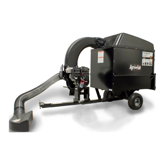
MOW-N-VAC
.
Want more information or assembly tips?
Scan with free ShowUHow Mobile App
available at iTunes Store or Android Market.
Or visit www.agri-fab.com for product
assembly instructions.
Call 1-800-448-9282 for missing parts or assembly help.
FORM NO 49942 (02/16/12)
Advertisement
Table of Contents

Related Manuals for Agri-Fab MOW-N-VAC 501887

Summary of Contents for Agri-Fab MOW-N-VAC 501887
- Page 1 Safe Operation • Operating available at iTunes Store or Android Market. and Instructions • Maintenance Or visit www.agri-fab.com for product Carefully • Repair Parts assembly instructions. Call 1-800-448-9282 for missing parts or assembly help. the fastest way to purchase parts www.speedepart.com PRINTED IN U.S.A.
-
Page 2: Table Of Contents
TABLE OF CONTENTS SAFETY RULES ............3,4 STORAGE ..............16 FULL SIZE HARDWARE CHART ......5,13 TROUBLESHOOTING ..........17 CARTON CONTENTS ..........6 REPAIR PARTS ILLUSTRATIONS ....19,20,22 ASSEMBLY ..............7 REPAIR PARTS LISTS ........19,21,22 OPERATION .............. 15 SLOPE GUIDE ............23 MAINTENANCE ............ -
Page 3: Safety Rules
SAFETY Any power equipment can cause injury if operated improperly or if the user does not understand how to operate the equipment. Exercise caution at all times, when using power equipment. • Read and follow all instructions in this manual before attempting •... - Page 4 WARNING TO AVOID SERIOUS INJURY • Read Owner's Manual and all safety labels on machine before starting and using machine. • Do Not remove top cover or attempt to empty contents of cart while engine is running. • Do Not stand behind cart in exhaust discharge area while engine is running. • Keep hands, feet, face, long hair and clothing out of chipper inlet, vac inlet, and discharge area. There are ROTATING BLADES inside these openings. • Wear approved safety glasses and gloves. Avoid loose fitting clothes. • Keep the area of operation clear of all persons, particularly small children and pets. • Keep all shields and guards (e.g. upper chipper chute extension, discharge chute, nozzle assembly) in place and securely attached. • Check discharge boot frequently for wear. Replace if worn or damaged. • If unit becomes clogged or jammed, shut off engine right away. Do Not attempt to clear clog or jam with engine running. • Muffler and engine get hot and can cause burns. Do Not Touch. To avoid a fire hazard, keep leaves, grass and other combustible debris off hot muffler and engine. • Do Not attempt to remove or attach vac nozzle or optional Hose Kit with engine running. • Do Not operate unit unless nozzle or optional Hose Kit is secured in place. • Do Not fill gas tank while engine is running. Allow engine to cool at least 2 minutes before refueling. DANGER DANGER HAZARDOUS ROTATING BLADES INSIDE. KEEP HANDS AWAY FROM ALL OPENINGS. DO NOT REMOVE OR ATTACH HOSE, HOSE ADAPTER, ELBOW OR OPTIONAL HOSE KIT WHEN ENGINE IS RUNNING! MUFFLER AND ADJACENT AREAS MAY EXCEED 150 F 777-5863...
-
Page 5: Full Size Hardware Chart
HARDWARE PACKAGE CONTENTS SHOWN FULL SIZE NOT SHOWN FULL SIZE See page 13 for contents of Deck Adapter hardware package. (Contents not included here.) REF. PART QTY. DESCRIPTION REF. PART QTY. DESCRIPTION Cart Vac Cart Vac 43574 — Bolt, Hex 3/8" x 3" 47810 Nylock Hex Nut, 5/16" 43351 — Bolt, Hex 1/2" x 1-1/4" HA21362 —... -
Page 6: Carton Contents
CARTON CONTENTS (Cart Body Carton) REF. PART NO. QTY. DESCRIPTION REF. PART NO. QTY. DESCRIPTION 23507 Wheel Support 41882 Hose ----- Rear Tongue w/Latch 62458 Tailgate Reinforcement Bracket 63155 Front Tongue 24897 Axle 49974 Hose Hanger Rod 24497 Latch Stand Bracket 23985 Cart Body 42159 Wheels... -
Page 7: Assembly
ASSEMBLY This unit is shipped WITHOUT GASOLINE or OIL. After 3. Fit the tailgate reinforcement bracket over the end of the assembly, see separate engine manual for proper fuel and cart bed. Position the two door support brackets on the engine oil recommendations. - Page 8 7. Assemble the wheel support to the bottom of the cart 10. Position the rear tongue on the wheel support and the latch stand bracket. Assemble the axle through the wheel using eight 5/16" x 3/4" truss head bolts and 5/16" Nylock support and the tongue.
- Page 9 ASSEMBLING VAC PARTS 13. Flip the cart over so that it rests on its wheels. 14. Assemble the front tongue on top of the rear tongue using three 3/8" x 3" hex bolts and 3/8" Nylock hex nuts. 17. Release the latch lock lever and tilt the cart bed back. See figure 8.
- Page 10 20. Place a side panel on top of the cart bed flange, inside 23. Assemble a door latch at each end of the cross brace the lip of the front panel. Fasten the side panel to the front using a 5/16" x 3/4" hex bolt, a nylon washer and a panel using three 1/4"...
- Page 11 25. Assemble a short tarp strap to rear door using one 1/4" x 29. Assemble the elbow to the impeller housing using 1-1/4" hex bolt, two 1/4" flat washers and one 1/4" Nylock four 5/16" x 3/4" self tapping hex bolts and four nylon hex nut.
- Page 12 32. Assemble the hose adapter (nozzle) to the front of 35. Place the hose hanger rod assembly into the hose the impeller housing and secure with the three knobs. hanger bracket on the impeller housing assembly. See Make sure that the switch actuator bracket contacts figure 20.
- Page 13 Segment 6. marking around a piece of cardboard held against the edge of the deck's discharge opening. Or visit www.agri-fab.com for product assembly instructions. 2. FOLLOW THE INSTRUCTIONS PRINTED ON THE TEMPLATE. If there are no instructions, use the following instructions as a general guide.
- Page 14 5. Position the adapter over the deck opening, and check 7. Assemble the adapter bracket to the deck using two for fit of cutout as shown in figure 24. Trim cutout, if 5/16" x 1" hex bolts, 5/16" flat washers and 5/16" necessary, to allow tilting of adapter, keeping the fit as Nylock hex nuts.
-
Page 15: Operation
OPERATION BEFORE STARTING HOW TO USE YOUR MOW-N-VAC 1. Your Mow-N-Vac engine is shipped without oil or gasoline. CAUTION: Service the Mow-N-Vac engine with oil and gas as Vehicle braking and stability instructed in the separate engine manual. may be affected with the addition of an 2. -
Page 16: Maintenance
MAINTENANCE CUSTOMER RESPONSIBILITIES • Read and follow the maintenance schedule and the maintenance procedures listed in this section. MAINTENANCE SCHEDULE Fill in dates as you Service Dates complete regular service. Check for loose fasteners Check soft vinyl boot Check tire pressure Check engine oil level Lubricate Clean... -
Page 17: Troubleshooting
TROUBLESHOOTING PROBLEM POSSIBLE CAUSE(S) CORRECTIVE ACTION Engine fails to start 1. Spark plug wire disconnected. 1. Connect wire to spark plug. 2. Safety switch not contacted. 2. Correctly install hose adapter nozzle. 3. Fuel tank empty, or stale fuel. 3. Fill tank with clean, fresh fuel. 4. - Page 18 NOTES...
- Page 19 PARTS REPAIR PARTS FOR MOW-N-VAC CART BODY MODELS 501887, 501888, 551887, 551888, 190-217D-100 & 190-217E-100 REF. PART NO. QTY. DESCRIPTION REF. PART NO. QTY. DESCRIPTION 23985 Cart Body 63917 Tongue Weldment Ass'y. (Rear) 62458 Tailgate Reinforcement Bracket 63155 Tongue Weldment Ass'y. (Front) 23507 Wheel Support 24614 Latch Lock Lever 24497 Latch Stand Bracket 23475 Hitch Bracket 24897 Axle, Wheel 1"...
- Page 20 REPAIR PARTS FOR MOW-N-VAC MODELS 501887, 501888, 551887, 551888, 190-217D-100 & 190-217E-100 39 7 ADAPTER #62468 TRACTOR...
- Page 21 REPAIR PARTS FOR MOW-N-VAC MODELS 501887, 501888, 551887, 551888, 190-217D-100 & 190-217E-100 PART NO. QTY. DESCRIPTION PART NO. QTY. DESCRIPTION 24080 Engine Base 43910 Washer, Flat 3/16" 24078 Brace, Housing 24798 Boot Mounting Strap 63226 Hose Hanger Bracket Ass'y. 48133 Hard top Boot (Ref. item #16 on page 22.) 44790 Poly Rear Door 43182 Bolt, Hex 5/16-18 x 3/4"...
- Page 22 REPAIR PARTS FOR MOW-N-VAC IMPELLER HOUSING ASSEMBLY MODELS 501887, 501888, 551887, 551888, 190-217D-100 & 190-217E-100 For removing impeller assembly. Must be ordered separately. REF. PART NO. QTY. DESCRIPTION REF. PART NO. QTY. DESCRIPTION 629-0241A Harness, Wire 726-0272 Clamp 24634 Housing Ass'y. Inner 731-1613 Cover, Switch 24633 Housing Ass'y. Outer 24958 Hose Hanger Bracket 43182 Bolt, Hex 5/16-18 x 3/4" 24606 Spacer, Housing 710-0772...
-
Page 23: Slope Guide
SLOPE GUIDE (Keep this sheet in a safe place for future reference.) Use this guide to determine if a slope is safe for the operation of your tractor and Mow-N- Vac. Refer also to the instructions in your vehicle owners manual. -
Page 24: Parts Ordering
Agri-Fab, Inc. Unauthorized uses and/or reproductions of this manual will subject such unauthorized user to civil and criminal penalties as provided by the United States Copyright Laws.
Need help?
Do you have a question about the MOW-N-VAC 501887 and is the answer not in the manual?
Questions and answers