Table of Contents
Advertisement
Quick Links
Advertisement
Table of Contents

Summary of Contents for Ultrasonic Poultry Systems 5300
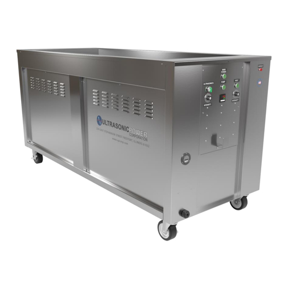
- Page 1 Console System Manual Ultrasonic Power Corporation 239 E. Stephenson Street Freeport, IL 61032, U.S.A. Phone: 815-235-6020 • 1-800-575-0168 Fax: 815-232-2150 Email: sonic@upcorp.com Website: www.upcorp.com Property of Ultrasonic Power Corporation - © 2021 Publication Number UPC211216-006...
- Page 2 Congratulations, You have just purchased the best ultrasonic cleaning system available to the market today. We here at Ultrasonic Power Corporation take pride in our products and our ability to provide our customers with the best quality service available. Please take some time to familiarize yourself with this manual and all aspects of the system configuration prior to start-up.
-
Page 3: Table Of Contents
Table of Contents Warnings ......................... 4 1. Specifications ......................8 2. Principles of Operation ....................14 3. Operating Instructions ....................15 4. Inspection and Maintenance ..................20 5. Troubleshooting......................22 6. Component Repair and Replacement ..............23 7. Diagrams and Drawings .................... 27 8. -
Page 4: Warnings
Warnings Warning Symbols Danger The DANGER symbol means that failure to follow this safety statement WILL result in personal injury or death. Warning The WARNING symbol means that failure to follow this safety statement MIGHT result in personal injury or death. Caution The WARNING symbol means that failure to follow this safety statement MIGHT result in personal injury or property damage. - Page 5 SAFETY PRECAUTIONS The following safety precautions should be observed when operating or servicing this equipment. WARNING: Utilize this equipment with accordance to the manual and good safety practices. Failure may result in poor equipment performance, personnel injury or death, or equipment damage. WARNING: Use only water or water-detergent mix in tank.
- Page 6 SAFETY PRECAUTIONS (Continued) Do not attempt to override safety interlocks. Never reach across any system which has not been turned off, the plug pulled, and high voltage capacitors discharged. When servicing live electronic equipment, always work with one hand in your pocket or behind your back, and stand on an insulated pad (e.g., rubber).
- Page 7 SAFETY PRECAUTIONS (Continued) WARNING: The transducers can build up a charge, regardless of power being applied, due to the mechanical shock or heat of solution in tank. Therefore, to remove shock hazard, disconnect transducer cable and short the cable to ground before servicing the generator. Use caution when working on the transducer assembly.
-
Page 8: Specifications
1. Specifications 39 Gallon / Tenor Standard Overall Length 23” Overall Width 51” Overall Height 40” Tank Length 18” Tank Width 32” Tank Depth 16” Working Depth 14” Tank Volume 39 Gallons Working Liquid Volume 35 Gallons Weir Volume Weight (Empty)** 150 lbs Electrical Supply 230V/240V-1P... - Page 9 39 Gallon / Tenor Fuse Schedule* Standard Control Circuit Fuse 250V / 1A Control Circuit Fuse 250V / 1A Ultrasonic Generator Fuse 250V / 10A Ultrasonic Generator Fuse 250V / 10A Heater Fuse 250V / 10A Heater Fuse 250V / 10A Pump Fuse 250V / 2A Pump Fuse...
- Page 10 90 Gallon / Bass Standard Overall Length 27” Overall Width 66” Overall Height 43” Tank Length 22” Tank Width 48” Tank Depth 20” Working Depth 18” Tank Volume 90 Gallons Working Liquid Volume 82 Gallons Weir Volume Weight (Empty)** 375 lbs Electrical Supply 230V/240V-1P Requirements*...
- Page 11 90 Gallon / Bass Fuse Schedule* Standard Control Circuit Fuse 250V / 1A Control Circuit Fuse 250V / 1A Ultrasonic Generator Fuse 250V / 12A Ultrasonic Generator Fuse 250V / 12A Heater Fuse 250V / 15A Heater Fuse 250V / 15A Pump Fuse 250V / 2A Pump Fuse...
- Page 12 135 Gallon / Contrabass Standard Overall Length 29” Overall Width 77” Overall Height 43” Tank Length 24” Tank Width 54” Tank Depth 24” Working Depth 22” Tank Volume 135 Gallons Working Liquid Volume 123 Gallons Weir Volume Weight (Empty)** 700 lbs Electrical Supply 230V/240V-1P Requirements*...
- Page 13 135 Gallon / Contrabass Fuse Schedule* Standard Control Circuit Fuse 250V / 1A Control Circuit Fuse 250V / 1A Ultrasonic Generator Fuse 250V / 20A Ultrasonic Generator Fuse 250V / 20A Heater Fuse 250V / 20A Heater Fuse 250V / 20A Pump Fuse 250V / 2A Pump Fuse...
-
Page 14: Principles Of Operation
An ultrasonic cleaning system consists of the following components: 1. An ultrasonic generator capable of producing high frequency electrical energy. Ultrasonic Power Corporation utilizes our 5300/5400 series generators. ® 2. Vibra-bar transducer technology to convert electrical energy received from the generator into mechanical energy. -
Page 15: Operating Instructions
3. Operating Instructions 3.1. General The following instructions are intended to guide the user when: (1) instructing operators in techniques designed to ensure optimum equipment performance; and (2) verifying the validity of operator complaints. See Section 4 - Troubleshooting, if the system is not operating properly. - Page 16 3.4. Operating the Equipment 1. Getting Started – Locate the unit on a solid and level surface. 2. Filling the Unit – Check to be sure the drain valve is tightly closed. Fill the tank up to the recommended working level with high quality water (A good rule of thumb is to fill the tank to ¾...
- Page 17 Tapping the “P” key will cycle between pages. There are three pages in total: 1. Current Temperature (Red) & Set Temperature (Green) • Use the arrow keys to adjust set temperature 2. Current Temperature (Red) & Time Remaining (Green) • Press “F” key to start the timer. Pressing “F” while the timer is running will stop the timer and cause it to reset.
- Page 18 8. System Degassing – If new water and detergent has been added allow the system to run for ten minutes at 80% power. This allows the water in the cleaning tank to properly degas (the water comes to oxygen equilibrium). The degassing process removes unwanted air molecules from the cleaning tank, thus maximizing the efficiency of the cavitation/cleaning process.
- Page 19 Do not place items to be cleaned directly on the tank bottom. The bottom is essentially a high frequency speaker so contact may hinder the acoustic propagation. Use UPC approved baskets or fixtures that are designed to minimize acoustical losses and or damage to the tank bottom and the transducers. Heavy items should always be suspended or placed on a work rest.
-
Page 20: Inspection And Maintenance
4. Inspection and Maintenance 4.1. General The maintenance described in this section should be performed at best intervals determined by the usage of the equipment, unless otherwise indicated. Should a problem occur when operating the unit, refer to Section 5, Troubleshooting. If a policy requires for calibration of the unit, the generators would be the only calibrated items that UPC recommends calibrating. - Page 21 CAUTION: Never turn on the system without having at least 8” of liquid in the tank or damage to the heating system will occur. b. HEATER – Press the HEATER button to turn it ON. Over time, the liquid will heat up. Turning on the ultrasonics during heat up will shorten heating time.
-
Page 22: Troubleshooting
5. Troubleshooting Only trained personnel are allowed into the inside of the machine. 5.1 General This section contains detailed information for locating and correcting malfunctions. The following steps provide an effective approach to the use of this information in conjunction with other areas of the manual. Check to be sure that the system has the minimum specified level of water in the cleaning tank and that the system has power prior to troubleshooting. -
Page 23: Component Repair And Replacement
6. Component Repair and Replacement Only trained personnel are allowed into the inside of the machine. 6.1. GENERAL This section includes instructions for the adjustment, disassembly, repair and replacement of selected components. Illustrations showing the various parts and assemblies referred to in this Section are in Section 7. If ever unsure during this process, contact your Ultrasonic Power Corporation representative. - Page 24 6.2. MODEL 5300/5400 GENERATOR NOTE: Use the following procedure whenever the generator is not operating properly. Do not attempt to do more than is listed below as it may void the warranty. 1. Remove power from system. 2. Check fuses (on control panel and on back of generator), replace if necessary.
- Page 25 6.4. HEATERS 1. Remove power from the system. 2. Check heater fuses located on the inside of the control panel. 3. Check heater pad for proper contact with the system tank. 4. Check for loose or damaged wires. If damage is visible, contact Ultrasonic Power Corporation service department for repair or replacement.
- Page 26 4. Check for plumbing for leaks. 5. Inspect pump for damage and/or loose wires. 6. Turn pre-strainer valve to "OFF" position. Unscrew transparent pre-strainer and remove contaminants from mesh screen. Return screen to pre-strainer. Ensure washer is seated properly. Hand-tighten pre-strainer back in place.
-
Page 27: Diagrams And Drawings
7. Diagrams and Drawings 7.1. 39 Gallon / Tenor Console Drawings and Schematics 39 Gallon / Tenor Console Standard Drawing Property of Ultrasonic Power Corporation - © 2021 Publication Number UPC211216-006... - Page 28 39 Gallon / Tenor Console Standard Schematic Property of Ultrasonic Power Corporation - © 2021 Publication Number UPC211216-006...
- Page 29 90 Gallon / Bass Console Drawings and Schematics 90 Gallon / Bass Console Standard Drawing Property of Ultrasonic Power Corporation - © 2021 Publication Number UPC211216-006...
- Page 30 90 Gallon / Bass Console Standard Schematic Property of Ultrasonic Power Corporation - © 2021 Publication Number UPC211216-006...
- Page 31 135 Gallon / Contrabass Console Drawings and Schematics 135 Gallon / Contrabass Console Standard Drawing Property of Ultrasonic Power Corporation - © 2021 Publication Number UPC211216-006...
- Page 32 135 Gallon / Contrabass Console Standard Schematic Property of Ultrasonic Power Corporation - © 2021 Publication Number UPC211216-006...
-
Page 33: Warranty
8. Warranty THE TEN-FIVE-TWO WARRANTY (the “Warranty”) Ultrasonic Power Corporation (“UPC”), as Manufacturer, warrants all products manufactured by UPC (“Products”) meet UPC’s production and quality assurance specifications before being released for distribution. Accordingly, UPC warrants that from the date of shipment from UPC’s facility: The bond for the VIBRA-BAR®... - Page 34 WARRANTY DISCLAIMERS THE WARRANTIES PROVIDED HEREIN ARE THE EXCLUSIVE WARRANTIES AND ARE EXPRESSLY GIVEN IN LIEU OF ALL OTHER WARRANTIES, EXPRESS OR IMPLIED, INCLUDING, BUT NOT LIMITED TO, IMPLIED WARRANTIES OF MERCHANTABILITY AND FITNESS FOR A PARTICULAR PURPOSE, WHICH ARE HEREBY DISCLAIMED.
-
Page 35: Return Of Equipment Policy
9. Return of Equipment Policy Replacement/Repair Policy and Pricing Schedule It is the intention of Ultrasonic Power Corporation (UPC) to deliver fair, accurate, cost-effective and timely service associated with warranty and non-warranty product assistance to Original Equipment Manufacturers (OEM), End- user and Reseller Customers within the guidelines of this Policy. - Page 36 be responsible for damaged and/or lost product prior to receipt by UPC at UPC’s facility. Return shipping (only) to the Customer will be paid by UPC and will be sent via standard ground shipping upon completion of a warranty or replacement/warranty repair.
- Page 37 Reshipment or Relocation When relocating or reshipping the system, ensure that the power has been disconnected and that the liquid has been entirely drained from the system prior to movement. Wipe down the system to remove all excess liquid. Wrap up the power cable to avoid presenting a tripping hazard.
-
Page 38: Standard Pricing Schedule
Standard Pricing Schedule Repair Rates (250W/500W Generators) Comments Warranty Repair $0.00 UPC Warranty Applies Test/Evaluation Fee $105.00 Waived with warranty replacement due to defect Expired warranty, equipment malfunction, customer NON‐Warranty $425.00 damage Repair Rates (750W/1000W Comments generators) Warranty Repair $0.00 UPC Warranty Applies Test/Evaluation Fee $145.00... -
Page 39: Rma Form
From: RMA # Ship To: Ultrasonic Power Corporation 239 East Stephenson Street Freeport, IL 61032 Attention: RMA Coordinator =============================cut here========================== FRAGILE ELECTRONIC EQUIPMENT Property of Ultrasonic Power Corporation - © 2021 Publication Number UPC211216-006... -
Page 40: Parts List
10” Filter Housing 50-70-769 Gauge for Filter housing 50-70-770 Pump - 240V (2-MD-HC) 50-55-287 Pump - 240V (3-MD-HC) 50-55-692 5300 Generator (240V/1000W/40kHz) 53-40-418-9 5300 Generator (240V/500W/40kHz) 53-40-456-9 Push Button Assembly - Green Green push button 50-06-054-G Contact block (2 each required) - Page 41 Please contact Ultrasonic Power Corporation for other system parts not Listed or any question regarding your ultrasonic cleaning system. 815-235-6020 or 1-800-575-0168 Property of Ultrasonic Power Corporation - © 2021 Publication Number UPC211216-006...
Need help?
Do you have a question about the 5300 and is the answer not in the manual?
Questions and answers