Table of Contents
Advertisement
Quick Links
Advertisement
Table of Contents

Summary of Contents for Lambda Lucid Series
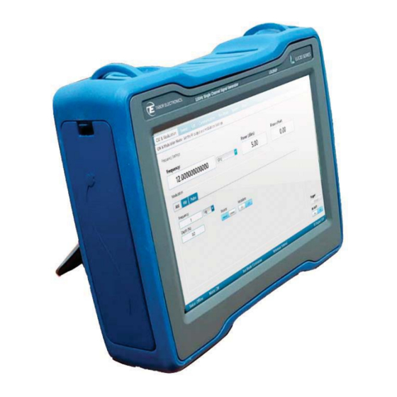
- Page 1 L L ucid Series RF Analog Signal Generator Portable Model User Manual Rev. 1.1 Distribution in the UK & Ireland Lambda Photometrics Limited Lambda House Batford Mill Harpenden Herts AL5 5BZ United Kingdom info@lambdaphoto.co.uk W: www.lambdaphoto.co.uk +44 (0)1582 764334 +44 (0)1582 712084...
- Page 2 Rev. 1.1 Lucid Series RF Signal Generator Portable User Manual WARRANTY STATEMENT Products sold by Tabor Electronics Ltd. are warranted to be free from defects in workmanship or materials. Tabor Electronics Ltd. will, at its option, either repair or replace any hardware products which prove to be defective during the warranty period.
-
Page 3: Table Of Contents
Rev. 1.1 Lucid Series RF Signal Generator Portable User Manual T T able of Contents Table of Contents..............................3 List of Figures ................................. 4 List of Tables ................................4 Document Revision History ............................ 5 Acronyms & Abbreviations ............................ 6 General ................................9 Scope .............................. -
Page 4: List Of Figures
Rev. 1.1 Lucid Series RF Signal Generator Portable User Manual Frequency ............................42 Amplitude ............................42 Phase Noise and Harmonics ......................43 Modulation ............................43 Inputs ............................... 45 Outputs ............................45 General ............................46 L L ist of Figures Figure 1.1 LS1291P – 12GHz One Channel RF Analog Signal Generator ............9 Figure 2.1 LS1291P Front Panel ........................ -
Page 5: Document Revision History
Rev. 1.1 Lucid Series RF Signal Generator Portable User Manual Table 5.3 Phase Noise and Harmonics Specification .................. 43 Table 5.4 Modulation Specification ......................43 Table 5.5 Inputs Specification ........................45 Table 5.6 Outputs Specification ........................45 Table 5.7 General Specification ........................46... -
Page 6: Acronyms & Abbreviations
Rev. 1.1 Lucid Series RF Signal Generator Portable User Manual A A cronyms & Abbreviations Table Acronyms & Abbreviations Acronym Description μs or us Microseconds Analog to Digital Converter Amplitude Modulation ASIC Application-Specific Integrated Circuit Automatic Test Equipment Arbitrary Waveform Generators Arbitrary Waveform Transceiver Bayonet Neill–Concelm (coax connector) - Page 7 Rev. 1.1 Lucid Series RF Signal Generator Portable User Manual Acronym Description Intermediate Frequency Input / Output Internet Protocol In-phase Quadrature Interchangeable Virtual Instrument JSON JavaScript Object Notation Kilohertz Liquid Crystal Display Local Oscillator Media Access Control (address) Mini D Ribbon (connector)
- Page 8 Rev. 1.1 Lucid Series RF Signal Generator Portable User Manual Acronym Description Software Front Panel Subminiature version A connector Subminiature Push-on connector Serial Peripheral Interface SRAM Static Random-Access Memory Thin Film Transistor T&M Test and Measurement Test Program Sets UART...
-
Page 9: General
Portable User Manual General Scope The scope of this manual is to describe the setup and operating procedures of the Lucid Series RF Analog Signal Generator. The manual covers the following models listed in the below ordering information. Table 1.1 Ordering Information... -
Page 10: Software Support
The Lucid Control Panel is a software package that comes on a CD supplied with the device. It enables full control and programming of your Tabor Electronics Lucid series RF analog signal generators via a user-friendly graphical user interface. The TE Update Tool is a utility for updating the Lucid device FPGA. - Page 11 Rev. 1.1 Lucid Series RF Signal Generator Portable User Manual x Do not operate in dark or wet conditions. x Do not operate in an explosive environment. Keep product clean and dry.
-
Page 12: Maintenance
Rev. 1.1 Lucid Series RF Signal Generator Portable User Manual 1 1 .5 Maintenance 1.5.1 Preventive Maintenance There are no hardware adjustments within Lucid Generators. Tabor Electronics Ltd., recommends that the Lucid Generator is calibrated every 12 months or whenever a problem is suspected. The specific calibration interval depends upon the accuracy required. -
Page 13: Introduction
USB interface and removable micro-SD card. The Lucid Series is designed to meet today’s most demanding applications, whether in the lab or out in the field. -
Page 14: Right Side Panel
Rev. 1.1 Lucid Series RF Signal Generator Portable User Manual 2 2 .3 Right Side Panel Remove the right-side cover of the ruggedized case to replace the battery. Figure 2.2 Right Side Panel TBD x Battery – Rechargeable battery 14.4 V, Lithium Ion, 3.35 Ah Left Side Panel Remove the left-side cover of the ruggedized case to access the connectors. - Page 15 Rev. 1.1 Lucid Series RF Signal Generator Portable User Manual x AM IN – A SMA type connector for an input from an external amplitude modulation source. x FM IN – A SMA type connector for an input from an external frequency modulation source.
-
Page 16: Portable Gui
Rev. 1.1 Lucid Series RF Signal Generator Portable User Manual Portable GUI CW Tab The CW (Carrier Wave) tab becomes available on the front panel display after power-up of the generator. From here the user can set the basic output parameters of the generator. -
Page 17: Modulation Tab
Rev. 1.1 Lucid Series RF Signal Generator Portable User Manual ƒ Continuous – The device will generate a signal when the user clicks the RF OUT On button. ƒ Trigger – The device waits for an external trigger event. –... -
Page 18: Fm - Frequency Modulation
Rev. 1.1 Lucid Series RF Signal Generator Portable User Manual External – Use an AM source connected to the generator’s MODULATION IN connector located on the rear panel. The Generator will accept modulating signals between DC and 100 kHz within ±1 V (2 V p-p) amplitude. -
Page 19: Pulse Definition
Rev. 1.1 Lucid Series RF Signal Generator Portable User Manual Figure 3.4 PM – Phase Modulation x Frequency – Set the modulation Frequency (Hz). x Deviation – Set the phase deviation degree of the modulation frequency. x Push the Mod On/Off button on the device front panel to start the modulation and then RF On/Off button to output the signal. -
Page 20: Pattern Sequence
Rev. 1.1 Lucid Series RF Signal Generator Portable User Manual x Frequency – Set the pulse frequency in Hz. x Source: Internal – Use the screen modulation parameters. External – Use a pulse source connected to the generator’s MODULATION IN connector ... - Page 21 Rev. 1.1 Lucid Series RF Signal Generator Portable User Manual 6. Enter the duration of the pulse (Time On), the delay for next pulse (Time Off), and the number of repetitions (Loops) of this step. 7. -STEP – Click the button to delete the last step.
-
Page 22: Sweep Tab
Rev. 1.1 Lucid Series RF Signal Generator Portable User Manual 3 3 .3 Sweep Tab The Sweep tab menu allows you to define a signal that sweeps over a frequency or power range. You can also push the Sweep button on the front panel to show the screen. -
Page 23: Power Sweep
Rev. 1.1 Lucid Series RF Signal Generator Portable User Manual x # Steps – sets the number of steps in one sweep (including Start and Stop). The value displayed in Step Size changes accordingly. 3 3 .3.2 Power Sweep Select the Sweep tab, and then click the PWR button. You can now define a signal that sweeps from one amplitude to the next, maintaining the same frequency. -
Page 24: List Tab
Rev. 1.1 Lucid Series RF Signal Generator Portable User Manual 3 3 .4 List Tab The List tab enables you to create and generate a sequence of signals that can vary in frequency, power and dwell time. You can also push the List button on the front panel to show the screen. -
Page 25: Run Mode Tab
Rev. 1.1 Lucid Series RF Signal Generator Portable User Manual 3 3 .5 Run Mode Tab The Run Mode Tab sets the mode by which the unit will run. E.g.; if the sweep starts generating the signals when the user clicks the Run button, or it will wait for an external trigger event. You can also push the Run Mode button on the front panel to show the screen. - Page 26 Rev. 1.1 Lucid Series RF Signal Generator Portable User Manual Step – for every trigger that is accepted the sweep or list is advanced by 1 step. While the step is being generated, any incoming trigger is ignored until the step is completed.
-
Page 27: System Tab
Rev. 1.1 Lucid Series RF Signal Generator Portable User Manual 3 3 .6 System Tab The System Tab manages the setup parameters of the entire system. You can load a system file to use a previously used system configuration. Figure 3.11 System Tab Following are the details of the System menu: x Serial –... -
Page 28: Preset
Rev. 1.1 Lucid Series RF Signal Generator Portable User Manual 3 3 .6.1 Preset Select on the device display the System tab, and then click the Preset button to set the system settings to factory defaults. A confirmation pop-up message is displayed. -
Page 29: Recall
Rev. 1.1 Lucid Series RF Signal Generator Portable User Manual 3 3 .6.3 Recall Select on the device display the System tab, and then click the Recall button to restore a stored settings of the entire system in a JSON (JavaScript Object Notation) format. You can select to restore the data from an SD card. -
Page 30: Update
Rev. 1.1 Lucid Series RF Signal Generator Portable User Manual Dynamic – Get an IP address from the DHCP server. The IP Address, Port and Subnet Mask fields are not accessible. x IP Address – Define a static IP address. -
Page 31: Troubleshooting
4.1.1 USB Device Driver Manual Installation (Windows 10) 1. Download the latest Lucid series USB device driver from www.taborelec.com/downloads. 2. Using the supplied USB cable, connect the Lucid Portable model to the PC. 3. Open the Start menu, and in the search field, type Device Manager. - Page 32 Rev. 1.1 Lucid Series RF Signal Generator Portable User Manual 5. In the navigation tree, expand Other devices and double click on CP2130 USB-to-SPI Bridge.
- Page 33 Rev. 1.1 Lucid Series RF Signal Generator Portable User Manual 6. The CP2130 USB-to-SPI Bridge Properties window opens. Click Update Driver.
- Page 34 Rev. 1.1 Lucid Series RF Signal Generator Portable User Manual 7. In the Update Drivers - CP2130 USB-to-SPI Bridge window, select Browse my computer for driver software. 8. Browse to the driver software location on PC, select its folder and click OK.
- Page 35 Rev. 1.1 Lucid Series RF Signal Generator Portable User Manual 9. Driver download begins.
- Page 36 Rev. 1.1 Lucid Series RF Signal Generator Portable User Manual 10. After the download is complete, the driver installation begins. 11. After the installation is complete, the following success message is displayed: 12. Click Close to close the Update Drivers window and to proceed.
- Page 37 Rev. 1.1 Lucid Series RF Signal Generator Portable User Manual 13. In the CP2130 USB-to-SPI Bridge Properties window the displayed device status should be: The device is working properly.
-
Page 38: Usb Device Driver Manual Installation (Windows 7)
Portable User Manual 4 4 .1.2 USB Device Driver Manual Installation (Windows 7) 1. Download the latest Lucid series USB device driver from the Tabor Electronics Ltd., website. Device drivers are available at www.taborelec.com/downloads 2. Connect the Lucid Generator to the PC using the supplied USB Cable. - Page 39 Rev. 1.1 Lucid Series RF Signal Generator Portable User Manual 8. In the Update Drivers - CP2130 USB-to-SPI Bridge window, select Browse my computer for driver software. 9. Browse to the driver software location on PC, select the folder and click Next.
- Page 40 Rev. 1.1 Lucid Series RF Signal Generator Portable User Manual 10. After the driver software installation is complete, click Close.
- Page 41 Rev. 1.1 Lucid Series RF Signal Generator Portable User Manual 11. In the Device Manager, under Silicon Labs USB Devices, click Silicon Labs CP2130 USB to SPI Bridge. 12. In the CP2130 USB-to-SPI Bridge Properties window the device status should indicate the device is...
-
Page 42: Lucid Portable Specifications
Rev. 1.1 Lucid Series RF Signal Generator Portable User Manual Lucid Portable Specifications Frequency Table 5.1 Frequency Specification Frequency Range LS3081P 9 kHz to 3 GHz LS6081P 9 kHz to 6 GHz LS1291P 9 kHz to 12 GHz Resolution 0.001 Hz Phase Offset 0.01 deg... -
Page 43: Phase Noise And Harmonics
Rev. 1.1 Lucid Series RF Signal Generator Portable User Manual Up to 100 MHz ±0.3 (typ.) ±0.5 (typ.) 100 MHz to 3 GHz ±0.4 (typ.) ±0.6 (typ.) 3 GHz to 9 GHz ±0.7 (typ.) ±0.9 (typ.) Above 9 GHz ±1 (typ.) ±1.5 (typ.) - Page 44 Rev. 1.1 Lucid Series RF Signal Generator Portable User Manual Resolution 0.1 % or 1 Hz (the greater) Modulation Rate 1 MHz Resolution 1 Hz Amplitude Modulation AM Depth Type Linear Maximum Settable 90 % Resolution 0.1 % of depth Accuracy (1 kHz) <...
-
Page 45: Inputs
Rev. 1.1 Lucid Series RF Signal Generator Portable User Manual Step Change Linear Trigger Free run, external, bus, timer 5 5 .5 Inputs Table 5.5 Inputs Specification Inputs Pulse/Trigger Connector Type 1 x SMA Input Impedance 50 Ω Input Voltage... -
Page 46: General
Rev. 1.1 Lucid Series RF Signal Generator Portable User Manual Connector Type Number of Outputs 5 5 .7 General Table 5.7 General Specification General Voltage Range +12.0 to +12.6 V DC Supply Voltage: 12 V DC Power Consumption 60 W max. (45 W typ.) Display Type 10.1", 1280x800 TFT capacitive... - Page 47 Rev. 1.1 Lucid Series RF Signal Generator Portable User Manual Warranty 1-year or 3-year warranty plans...
Need help?
Do you have a question about the Lucid Series and is the answer not in the manual?
Questions and answers