
Summary of Contents for GoCNC CNC Studio USB
- Page 2 Congratulations on your purchase of CNC Studio. This software-hardware solution enables you to realize your CNC projects in the easiest possible way. We hope you enjoy this product. Your GoCNC.de Team © Copyright by: GoCNC.de Jan Domagala Uhlandstraße 24 58675 Hemer Germany www.gocnc.de info@gocnc.de...
-
Page 3: Table Of Contents
CNC#STUDIO#USB#USER#MANUAL#3# Table of Contents LEGAL!AND!GENERAL!INFORMATION………….………………………………………...2! WHY!CNC5STUDIO………………………………………………………………………………….……..4! WHAT!IS!CNC5STUDIO…………………………………………………………………………..……...4! SYSTEM!REQUIREMENTS……………………………………………………………..……………….5! TECHNICAL!FEATURES…………………………………………………………………….…………….5! IINSTALLATION………..……………………………………………………………………………….…..6! INSTALLATION!OF!THE!SOFTWARE…………………………………………………………….….6! MANUAL!DRIVER!INSTALLATION…….………………………………………………………….!10! FIRST!STEPS…………..………………………………………….………………………………………...15! PROGRAM!START!AND!FUNCTIONS…………………………………………………………….16! THE!“PROGRAM”!WINDOW………………………………………………………………….…….16! THE!“SETTINGS”!WINDOW………………………………………………………………………….18! THE!“EDIT!CNC!FILE”!WINDOW……………………………………………………………………21! THE!“STEPP!2500!SETTINGS”!WINDOW…………………………………………………….…21! SETTING!A!GOCNC!“HOBBY!A4!ADVANCED”!MILLING!MACHINE!....23! EMULATION…………………………………………………………………………….………………….26! HOMING!AND!MACHINE!ZERO!POINT…………………………..…………………………….28! PARK!POSITION.………………….…………………………………..………………………………….28! MILLING!EXAMPLE……….……………………………………….…………………………………….29! HPGL!FILE!PREPARATION…………………………………………………………………………….30! TOOL!LENGTH!SENSOR………………………………….…………………………………………….35! TOOL!CHANGE!PROCEDURE……………….……………………………………………………….35! VERSION!CHANGES……………….…………………………………………………………………….37! YOUR!NOTES……………………………………………………………………………………………….38! -
Page 4: Cnc#Studio#Usb#User#Manual#3
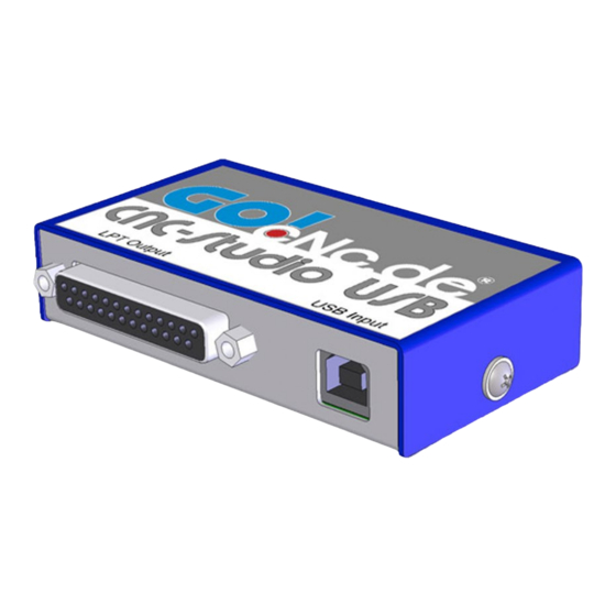
Windows background processes on the PC, which ensures an utterly clean, smooth and precise running motor. The CNC Studio USB can be used to control any CNC machine which has a parallel port and which uses clocking / direction signals as actuation. -
Page 5: Technical!Features
CNC#STUDIO#USB#USER#MANUAL#5# Technical#Features:# Easy plug-and-play hardware The software is very simple and intuitive to use Only one user interface, no bothersome switching between windows Operating instructions integrated in software and can be opened with one click of the mouse Runs on all PCs, notebooks and netbooks with at least 1Ghz output and USB connection USB 2.0 interface Machine control via small USB Box Works with all clocking/direction controller cards... -
Page 6: Installation!Of!The!Software
6###CNC#STUDIO#USB#USER#MANUAL# Installation#the#software# Start the file CNC-Studio-Setup.exe and follow the instructions on the screen Click the mouse on the “Continue” button mouse to start the installation. - Page 7 CNC#STUDIO#USB#USER#MANUAL#7# After you have finished reading the information about your software, click on “Continue Read the licence agreement, and if you agree with the conditions, click on “I agree” and then on “Continue”...
- Page 8 8###CNC#STUDIO#USB#USER#MANUAL# Select a target directory on your hard drive where you would like to install CNC-Studio and click the mouse on “Continue” You have to confirm the selected installation path by clicking the mouse on “Start.” Now wait a few seconds until the CNC-Studio software has been transferred to the hard drive.
- Page 9 CNC#STUDIO#USB#USER#MANUAL#9# Installation is complete. Click on “Continue” to close the installation program. Now you can find CNC-Studio under “Programs” in your Windows Start Menu.
- Page 10 10#CNC#STUDIO#USB#USER#MANUAL# Manual#installation#of#the#driver#under#Windows#Vista#and#Windows#7# Connect the CNC-Studio USB Box to your PC with the supplied USB cable. Afterwards, open the Control Panel in the Windows menu. Change the view setting of the window to “Large Symbols” and look for the “System” symbol. Start the program “System”...
- Page 11 CNC#STUDIO#USB#USER#MANUAL#11# A window will open listing all of the drivers for the devices on your PCs. Find the entry “Stepper Motor Controller” and double-click on it. In the new window that opens, “Properties of Stepper Motor Controller,” select the “Drivers” tab. Now double-click on “Driver details.”...
- Page 12 12#CNC#STUDIO#USB#USER#MANUAL# In the next window, click on Search and select the folder in which you installed the CNC-Studio software on your PC. That installation program also installed the required drivers in this folder. Check the box “Include subfolders” and then click on “Continue.”...
- Page 13 CNC#STUDIO#USB#USER#MANUAL#13# Depending on the security settings of your system, one of the following windows may open. In this case, simply select the option “Install this driver software anyway.” After a few seconds, the following window will appear: This concludes the installation of the drivers for the CNC-Studio. Check the parameters in the window “Properties of Stepper Motor Controller”...
- Page 14 14#CNC#STUDIO#USB#USER#MANUAL# Once the installation has been successfully completed, close the window “Properties of Stepper Motor Controller” Your Device Manager should now show a new device named “USB stepper motor controller.” Close the Device Manager window and the Control Panel window. CNC-Studio is ready to be started for the first time...
-
Page 15: Program!Start!And!Functions
CNC#STUDIO#USB#USER#MANUAL#16# Program#start#and#Functions# This section of the manual familiarizes you with the most important functions of CNC Studio and how to customize the settings on your machine. After the program and the driver have been installed successfully, you can start the CNC-Studio for the first time. -
Page 16: The!"Program"!Window
16#CNC#STUDIO#USB#USER#MANUAL# The#“Program”#Window# The main window of the program is depicted below: The main window is divided into different sections: Change program view. (upper right) These tabs can be used to switch between the displays “Program,” “Settings” and “Editor.” “Program” is the window that is currently open above. The “Program” window is used to operate your machine. - Page 17 CNC#STUDIO#USB#USER#MANUAL#17# Homing performs homing of all axes and parks at the machine zero point. Zero point set saves any position of the tool as the zero point and sets the coordinates to zero. Go to zero point moves to the saved zero point position. Go to park position –...
-
Page 18: The!"Settings"!Window
18#CNC#STUDIO#USB#USER#MANUAL# The#“Settings”#Window# Change the window display by selecting “Settings.” This is where all of the important parameters for the machine and for the milling of CNC job files are defined. The main window has been divided into different sections again and the functions are described individually. LPT port setting. - Page 19 CNC#STUDIO#USB#USER#MANUAL#19# Distance per revolution Machine parameter. This value must be taken from the data sheet of the machine. Steps for ramp Steps for acceleration and deceleration. The optimum value is achieved by trial and error. Reference switch location Position in which the reference switch is located in relation to the corresponding axis (left, right, front, back, top, bottom).
- Page 20 20#CNC#STUDIO#USB#USER#MANUAL# Measure tool now : (Always perform homing first) This function drives the machine over the tool length sensor, takes a measurement and then saves the measured value to the settings. Cancel Cancelled measure now Take current positions . Accepts the positions reached by the X and the Y axis as the position of the tool length sensor.
- Page 21 CNC#STUDIO#USB#USER#MANUAL#21# Edit#CNC#File# An HPGL Editor is installed in CNC Studio. In the “Editor” window you will see the following elements: Here is an overview of the integrated functions: Load file – loads a file from the hard drive in the Editor Save file –...
- Page 22 22#CNC#STUDIO#USB#USER#MANUAL# Stepp#2500#Settings## That!is!the!settings!Manual!for!often!used!Stepp!2500!CNC!board.! The!control!board!Stepp!2500!is!not!included!in!the!delivery. CNC!Studio!also!works!with!other!boards! Version!changes!
- Page 23 Refer to your controller card instructions for the parameters and match them with the settings in the software. In this example, a GoCNC Stepp 2500 controller card is being used since this is included as a standard accessory with the Hobby A4 machine. Set the signals as follows:...
- Page 24 24#CNC#STUDIO#USB#USER#MANUAL# First of all we will configure the X axis in the machine settings. Therefore, enter the following values for the X axis: Steps per rotation : 200 Micro steps 1,2,4,8,16 : 2 ( with 2 we are assuming that your controller card is set to 1/2 – that is, half-step –...
- Page 25 CNC#STUDIO#USB#USER#MANUAL#25# Finally, the Z axis is configured as follows: • Steps per rotation - 200 • Micro steps 1,2,4,8,16 Spindle pitch • - 1,5 • Steps for ramp - 100 Reference switch • - top Maximum speed mm/s • - 10 Start/stop speed •...
-
Page 26: Emulation
26#CNC#STUDIO#USB#USER#MANUAL# Emulation# With the “Emulation” command, you can graphically display the work process without milling the workpiece. Once you start emulation, CNC Studio will draw your CNC file job in the “Working area” section, delineating the milled lines in red and the linear movements in green. To start the emulation, first open a job file. - Page 27 CNC#STUDIO#USB#USER#MANUAL#27# Now click on the “Start emulation” button and CNC Studio will start the emulation of the job sequence without milling the job file. The speed of the emulation can be slowed down using the parameter “emulation delay.” Finished Emulation.
-
Page 28: Homing!And!Machine!Zero!Point
28#CNC#STUDIO#USB#USER#MANUAL# Homing#and#machine#zero#point# When operating a CNC machine, a homing run is often necessary. Homing defines the so-called reference points. These are specified by the manufacturer of the machine and are fixed measurements from the body of the machine. There is always one reference point for every possible axis (traverse path). After homing is started, all of the reference points of the machine are sought out. -
Page 29: Milling!Example
CNC#STUDIO#USB#USER#MANUAL#29# Milling#example# In this example, you will learn step-by-step how to mill an HPHL file. The pre-requisite is that the parameters of your machine and the LPT port have been set correctly. Only the parameters for the upcoming job need be defined. -
Page 30: Hpgl!File!Preparation
30#CNC#STUDIO#USB#USER#MANUAL# HPGL#file#preparation Version 1.0 of CNC Studio has an integrated HPGL interpreter. The interpreter recognizes the commands of the HPGL plotter language and converts these into machine signals. HPGL files can be created with a host of programs, such as CorelDraw, AutoCAD, AutoSketch, Eagle, HCAM or CADdy. The following is a brief description of how to create an HPGL file with Corel Draw. - Page 31 CNC#STUDIO#USB#USER#MANUAL#31# Please note the following: The middle of the tool (cutter) will always trace the line exactly when milling. Therefore, you must include the diameter of the tool in your drawings and calculate the drawn dimensions correctly during the drawing stage. If you draw a circle with a 20 mm diameter and use a 2 mm thick cutter to mill, the inner circle will have a diameter of 9 mm and the outer circle a diameter of 11 mm.
- Page 32 32#CNC#STUDIO#USB#USER#MANUAL# In the centre of the rectangle we’d like to have a round cut-out with a diameter of 50 mm. Select the “Circle” tool from the menu on the left and draw it inside the rectangle. Then change the values for the “Height” und “Width” of the object to 48 mm. The circle should now take on the entered dimensions.
- Page 33 CNC#STUDIO#USB#USER#MANUAL#33# from the “File” menu. If you cannot save the file as “HPGL My File.plt” here, then you have to select the option “Export” from the “File” menu. Before you save the file, it is very important that you select .plt as the file name ending since this ending stands for the HPGL format.
- Page 34 34#CNC#STUDIO#USB#USER#MANUAL# You can now import the finished file in the CNC Studio and experiment a little. This is how the file will appear in CNC Studio and emulate mill process...
-
Page 35: Tool!Length!Sensor
CNC#STUDIO#USB#USER#MANUAL#35# Tool#length#sensor# Sometimes it’s necessary to use different tools when working on a workpiece. In such cases it’s important to make sure that, when changing the tools, the height of the tool above the defined zero point is the same. Since most tools have different lengths, they have to be measured after being inserted in the milling spindle and the zero point has to be recalculated. - Page 36 36#CNC#STUDIO#USB#USER#MANUAL# Now click on “Go to park position.” As soon as your machine has reached the park position that you set earlier, change the tool manually and then click on “Measure tool.” Now the measuring process will be repeated for the new tool.
-
Page 37: Version!Changes
CNC#STUDIO#USB#USER#MANUAL#37# Version#Changes# For the latest version of the software and the user manual as well as free updates, please visit: www.gocnc.de/Downloads 24.06.2012- V1.0 – the first version 15.03.2012- V1.0a – the first update Include german and english language Include german und english manual Aenchance HPGL and HPGL2 interpreterwith various delimeters and PA commands. -
Page 38: Your!Notes
38#CNC#STUDIO#USB#USER#MANUAL# Your#Notes#... - Page 39 CNC#STUDIO#USB#USER#MANUAL#39#...
Need help?
Do you have a question about the CNC Studio USB and is the answer not in the manual?
Questions and answers