Table of Contents
Advertisement
Quick Links
Advertisement
Table of Contents

Related Manuals for ROJ PCS 200

Summary of Contents for ROJ PCS 200
- Page 1 PCS 200 Installation Operation Maintenance ORIGINAL INSTRUCTIONS...
- Page 2 ROJ reserves the right to change at any time the contents of this manual, without notice. For any technical or commercial problem, please contact your local ROJ dealer or call directly the ROJ customer service center. We will be glad to meet your needs.
- Page 3 PCS 200 INSTALLATION, OPERATION AND MAINTENANCE MANUAL Edition: October 2019 Revision: Direction and Plant: Via Vercellone 11 13900 Biella (BI) Tel. +39 015 84 80 111 Fax +39 015 84 80 209 E-mail: comm@roj.com www.roj.it...
-
Page 5: Table Of Contents
1.2.3 Machines on which the integration of the mentioned partly completed machinery is foreseen ....... 1.4 1.2.4 Acronyms used ............................... 1.4 COMPONENTS OF THE PCS 200 KIT ......................1.5 GENERAL INFORMATION ABOUT SAFETY ....................1.7 1.4.1 Design criteria ..............................1.7 1.4.2 Safety Devices and Solutions .......................... - Page 6 ORDINARY PREVENTIVE MAINTENANCE TASKS TO BE CARRIED OUT BY THE OPERATOR…………4.1 MAINTENANCE/REPAIR TASKS RESTRICTED TO SPECIALIZED PERSONNEL ........4.2 SPARE PARTS ............................... 4.3 PROCEDURE FOR THE MD REPLACEMENT OR EXCHANGE………………………………………………...4.5 UPDATES INDEX 9/18/2014 Edition 3/29/2016 Edition 10/10/2019 Edition - ii - PCS 200 Kit...
-
Page 7: Preface
ROJ put a special emphasis on all ESR 1.7.4 clauses during the drafting phase of these manual, in particular: 1. The ROJ user and maintenance manuals are supplied in the language of the machine destination country, within the European Union and, when necessary, Original language copy of the manual is also provided. -
Page 8: Safety
Machine. CE Marking identification The ROJ PCS xxx kits are CE marked on the back of the graphic display. - iv - PCS 200 Kit... -
Page 9: Compliance With The European Directives And Regulations
Conformity Declaration signed and released by the Manufacturer. Note 1: The PCS 100 and PCS 150 kits are a subset of the PCS 200 kit Note 2: The previous directive 2004/108/EC is repealed as from 04/20/2016 PCS 200 Kit... -
Page 10: Warranty And Responsibility Of The Manufacturer
Preface Warranty and Responsibility of the Manufacturer The PCS 200 system described in this manual has been designed to be incorporated into agricultural machinery (typically Seeders) and is therefore intended to operate exclusively in combination with the above mentioned machines. -
Page 11: General Information
1.1.1 The ideal solution to control and optimize the seeding process The PCS 200 kit has been designed for the installation on seeders in order to control and optimize the entire seeding process. Thanks to the exclusive flexibility and configurability the PCS 200 kit represents the best solution for pneumatic and precision seeders. -
Page 12: Symbols Used In This Manual
For more details about the recycling of this product, you may contact your municipal technical office, your local waste disposal service or the local dealer. Always recycle used batteries into special containers. DISPOSE OF BATTERIES IN AN ENVIRONMENT-FRIENDLY WAY - 1.2 - PCS 200 Kit... -
Page 13: General Information And Performances
1.2.1 Introduction The PCS 200 System has been designed to be applied on pneumatic and precision seeders (falling within the scope of the EN 14018 norm) in order to replace the mechanical transmission that drives the rotation of the seeding discs and the fertilizer distributors with electrical engines, operated by their relative control system. -
Page 14: Machines On Which The Integration Of The Mentioned Partly Completed Machinery Is Foreseen
EN 13849-1 Analog/Digital Converter Controller Area Network (BUS) Electronic control unit ISOBUS Communication standard for tractors and machinery for agriculture and forestry ISO-11783 Motor with integrated drive Power take-off Sub distribution board Human-Machine Interface console - 1.4 - PCS 200 Kit... -
Page 15: Components Of The Pcs 200 Kit
General Information COMPONENTS OF THE PCS FS KIT Figure 1-1 Main components of the PCS 200 kit TECHNICAL DATA Rated voltage: 12 VDC; Rated current: 4,2 A; Rated power: 80 W Geared motors Rated speed: 3000 rpm Electronic Control Processor: 80 Mhz; Flash memory 2.5 Mb; RAM: 128 Kb; NVRAM: 8 Kb;... - Page 16 General information Geared motor for the seeding elements and distributors fertilizer/granular fertilizer Electronic Control Unit Graphic display Sub distribution board - 1.6 - PCS 200 Kit...
-
Page 17: General Information About Safety
GENERAL SAFETY INFORMATION 1.4.1 Design criteria The principles introduced by the relevant paragraphs of the following Harmonized Standards have been adopted in the design and manufacturing of the PCS 200 equipment: EN ISO 12100: 2010 Safety of machinery. General principles for design. -
Page 18: Safety Devices And Solutions
Any attempt to remove or by-pass the safety measures installed, thus reducing the overall safety level, IS FORBIDDEN. The user is completely liable for any damage to objects or persons arising from the non-observance of the recommendations herein given. - 1.8 - PCS 200 Kit... -
Page 19: Warnings And Behaviour Rules For The Operator
☞ ROJ will assume no liability for any damages to people and/or properties arising from the non-observance of these warnings. Operators shall be properly trained to make best use of the equipment so to avoid ... -
Page 20: Noise Levels
The PCS 200 system has been designed to be incorporated into seeders. The use of the PCS 200 for different purposes may result in damage to persons or the equipment itself and is therefore considered as an Improper Use for which the Manufacturer will not be held responsible. -
Page 21: Installation
The following features refer to the geared motor outlet shaft (slow shaft) dimensions. Nominal torque 8.75Nm 19Nm (single pulse, duration 500ms) Peak torque 12Nm (repetitive, duration 500ms, every 5 second) Nominal speed 100 rpm PCS 200 Kit - 2.1 -... -
Page 22: Outlet Shaft Dimensions
In order to grant a suitable lubrication of the reduction phase, it is necessary not to exceed the maximum tilting indicated below. Figure 2-2 Tilting limits – For further information please make reference to the file 1061-angle.pdf - 2.2 - PCS 200 Kit... -
Page 23: Fastening
Fix the geared motor to the flange using the bushings, the M8x80 bolts and standard M8 washers, as illustrated in the following figure. We suggest locking the bolts with a thread locker. Tightening torque: 10 Nm. Figure 2-4 Particulars for the geared motor fastening – PCS 200 Kit - 2.3 -... -
Page 24: Dmd2
The geared motor outlet has got a shaft aligned with the fast shaft of the electric motor. The dimensions are shown in the technical drawing below. Figure 2-5 Outlet shaft dimensions – For further information, make reference to TD_DMD2_revI.pdf - 2.4 - PCS 200 Kit... -
Page 25: Fixing Flange Features And Geared Motor Fastening
This kind of geared motors can be easily fastened by fixing the reduction gear in the desired position. The fixing flange must be suited to bear an approx. weight of 1,5 Kg and 4 M4 screws are needed. Figure 2-5 Particulars for the geared motor fastening – PCS 200 Kit - 2.5 -... -
Page 26: Alternator
The pulleys (PTO and alternator side) should be chosen in order to reach a speed of 3000 rpm, at the PTO nominal speed. The shaft should rotate clockwise when observing the pulley front side from the alternator. Figure 2-6 - Alternator rotation direction - 2.6 - PCS 200 Kit... -
Page 27: Absorbed Mechanical Power And Radial Loads
Figure 2-6 - Alternator rotation direction Power required by PTO 4 kW Radial load on the alternator axis 1000N Table 2-1 - Main information for the alternator integration Figure 2-7 - Characteristic power curves for the alternator PCS 200 Kit - 2.7 -... -
Page 28: Battery
Single cogwheel sensor The speed sensor is implemented using a hall effect speed sensor type Cherry GS102301 (P/N ROJ 50A00174) and relevant cable (P/N ROJ 05R01400). This sensor detects the speed of a phonic wheel connected to the machine drive wheel. -
Page 29: Wheel Sensor Check
Carry out 2 complete wheel turns and check whether the number of counted pulses is correct (for example, if the teeth number = 45, the result should be = 90). • Press the "Cancel" button if you do not want to save the result PCS 200 Kit - 2.9 -... -
Page 30: Machine Position Sensor
Installation MACHINE POSITION SENSOR It is a mechanical proximity sensor (P/N ROJ 05R01422) used to define whether the machine is in seeding position (machine lowered) or in transfer position (machine lifted). Figure 2-10 Position sensor – The sensor must be fastened to the machine frame, in such a way that: •... -
Page 31: Position Sensor Check
30 poles connectors are not used in all configurations. In this case your can use the 30 poles ECU plug (P/N ROJ 05R01334) or a cable already fitted for the seeding test and pressure sensor button (P/N ROJ 05R01380). -
Page 32: Sdb Positioning
Figure 2-12 - Wiring diagram of the system with alternator ☞ The codes of the various elements are listed in the following pages. The items referred as 5 (alternator), 8 (battery) and 10 (battery disconnect switch) are not included in the kit. - 2.12 - PCS 200 Kit... - Page 33 Installation Figure 2- - Wiring diagram of the system without alternator PCS 200 Kit - 2.13 -...
-
Page 34: Main Components
05R01379 ECU 18P CABLE PCS 05R01334 ECU PLUG 30C 05R01380 ECU 30P CABLE PCS 50A00174 HALL EFFECT SPEED SENSOR GS102301 05R01400 GS102301 SPEED SENSOR CABLE L=1500mm 05R01422 MECHANICAL SWITCH SENSOR 05A00173 PRESSURE SENSOR - 2.14 - PCS 200 Kit... - Page 35 Installation Figure 2-14 ECU wiring diagram – PCS 200 Kit - 2.15 -...
-
Page 36: Sdb And Power Supply Cables Connection
Wago spring terminals in the area indicated by “ ” the black rectangle shown in the following figure ( Negative Figure 15 - SDB 12+12 connections These are acronyms for Top Left, Top Right, Bottom Left, Bottom Right respectively - 2.16 - PCS 200 Kit... - Page 37 14A00072 BATTERY INSULATORS (BORDEAUX NUTS) 05R01385 CAN TERMINATION (MOLEX ) SDB 05R01412 BAT-SOCKET ISO12369 05R01433 SDB-IF CABLE ☞ The quantity and type of distribution cables (3,6 or 7 outputs) differ for each machine configuration. PCS 200 Kit - 2.17 -...
- Page 38 Connect one cabling side (18-poles black CINCH connector) to the MD, and the 8- poles grey Deutsch connector has to be connected to the distribution cable (05R01404 cable 3 outputs 05R01372 cable 6 outputs or 05R01373 cable – – – outputs). - 2.18 - PCS 200 Kit...
- Page 39 The CAN on SDB (yellow rectangle in Figure 15 and Figure 16) unused sockets should be secured with the element no. 05R01385. Suitable to MDs for fertilizers and microgranulators Suitable to MDs for fertilizers and microgranulators PCS 200 Kit - 2.19 -...
-
Page 40: Safety Switch
The safety switch is not supplied with the kit as it must be chosen according to the dimensions requirements of the machine it will be installed on. Note: B10d is the reliability parameter declared by the device manufacturer, corresponding to the number of switchings which can be granted without errors. - 2.20 - PCS 200 Kit... - Page 41 Installation This page is intentionally left blank PCS 200 Kit - 2.21 -...
-
Page 42: User Manual
To turn the machine on, press the relative button on the top right of the display unit. Approx. 4 seconds later, the following screen appears on the HMI display. Once the loading phase is finished, the Home screen indicated by the top left “ ” icon is immediately displayed. PCS 200 Kit - 3.1 -... -
Page 43: Graphic Organization
It allows to quickly return to the home screen. It allows to return to the previous screen. It allows to access the active alarms window It allows to access the complete console menu Selected tab Not selected tabs - 3.2 - PCS 200 Kit... -
Page 44: Access Levels
The access to the tabs, buttons and numerical fields for the setup is organized as an access levels system. Therefore, some fields can be modified only by authorized users. For the PCS 200 system the following access levels are foreseen, in ascending order: Operator It is the standard access level and does not require any password. -
Page 45: Motors Addressing
It is also possible to force this operation, by opening the following window and clicking the button. Path: Machine Tab Field Description Activation button for the addressing procedure - 3.4 - PCS 200 Kit... -
Page 46: Machine Configuration
MD numbers of Seeding discs, Fertilizer spreaders and Microgranulators. MD addressing window Field Description It allows to modify the machine configuration If this button is pressed, the real addressing session starts To exit from the addressing window PCS 200 Kit - 3.5 -... -
Page 47: Addressing
A beep sound indicates that the motor has been correctly addressed “ ” and the icon turns to green. - 3.6 - PCS 200 Kit... - Page 48 In case of error, press the motor symbol in order to display the dialog Unaddress “ which allows to cancel the address of one, a group or all motors: ” MD addressing window Field Description Motor not yet addressed Motor to be addressed (flashing) Addressed motor PCS 200 Kit - 3.7 -...
- Page 49 MD addressing window Field Description It allows to modify the machine configuration If this button is pressed, the real addressing session starts To exit from the addressing window - 3.8 - PCS 200 Kit...
-
Page 50: Machine Configuration
(If selected, the user is asked to turn off and restart the system from the main disconnect switch/battery disconnect switch) When selecting Double sensor you need to specify the number of “ ” teeth of the phonic wheel (= number of pulses of the wheel between PCS 200 Kit - 3.9 -... - Page 51 If the sensor detects other seeds after the first one, these will be considered as doublets inside the angular window. “ ” It enables the hopper level sensor (if present) … - 3.10 - PCS 200 Kit...
- Page 52 For ex.: 4 MDs for the seeding rows + 2 MDs for the fertilizers # of rows Fertiliser 1 Fertiliser 2 # of rows Fertiliser 1 Fertiliser 2 PCS 200 Kit - 3.11 -...
- Page 53 Number of motors for the fertilizer spreader hoppers Reduction gear ratio multiplied by 100 (for example: -10000 ... 10000 reduction gear 28.89: 1 2889) The minus sign indicates rotation direction opposite to the standard one. - 3.12 - PCS 200 Kit...
- Page 54 For ex.: 4 MDs for the seeding rows + 2 MDs for the A/B Microgranulators # of rows Micro A1 or B1 Micro A2 or B2 # of rows Micro A1 or B1 Micro A2 or B2 PCS 200 Kit - 3.13 -...
-
Page 55: Seeding Settings
It enables the sprayer mode and activates the relay which … controls the weeding pump. Available over 0,5 km/h. It is calculated from the parameters set and indicates the … maximum rotation speed of the motor. If this speed is - 3.14 - PCS 200 Kit... - Page 56 Note: in order to improve the precision of the absolute value for the seeding distance, it is important to calibrate the seed sensor each time you change the field or if the soil conditions have changed, in order to compensate a different sinking of the tractor wheel. PCS 200 Kit - 3.15 -...
- Page 57 (see chapter Seeding disks disabling). Automatic recovery of the rows which have been switched off by On/off the manual tramline at the end of the field. This operation is done during the transition phase between lifted/lowered machine. - 3.16 - PCS 200 Kit...
- Page 58 This tab allows to individually set the disk holes as well as the seeding distance for each row, by directly selecting the parameters of the row you want to modify. Field Values range Description Number of holes on the seeding disk – 100 cm Seeding distance expressed in cm – PCS 200 Kit - 3.17 -...
- Page 59 It allows to measure the density of the product to be used. … (See below) It allows to calculate the volume cm³ of the auger/distributor … in use. A and B Microgranulators Tab - 3.18 - PCS 200 Kit...
- Page 60 It allows to measure the density of the product to be used. … (See below) PCS 200 Kit - 3.19 -...
- Page 61 It is possible to select the motor to be calibrated as well as the prefill speed to be used. After pressing the prefill button (for at least 3 complete turns of the auger), it will be possible to start the density measurement. The following screen is displayed - 3.20 - PCS 200 Kit...
- Page 62 The following pop-up window is displayed where it is possible to test the volumetric distributor. PCS 200 Kit - 3.21 -...
- Page 63 Tramline , i.e. the “ ” automatic row exclusion function. The manual function is already available in the HOME page by using the buttons you can find under the column of each seeding row. - 3.22 - PCS 200 Kit...
- Page 64 As regards the basic adjustments to be carried out before the beginning of the job, you can decide whether the first one is an advance or return passage. It is possible to make this adjustment by clicking directly the tractor icon with the following result: PCS 200 Kit - 3.23 -...
- Page 65 Machine alignment to the left (row 1 on the machine aligned with row 1 in the sequence) • Driving direction: advance Supposing that the sequence goes further without mistakes we will not need to use the buttons The following screen is displayed: - 3.24 - PCS 200 Kit...
- Page 66 As you can see, the working condition is: • Rows covered on the first passage: 4 PCS 200 Kit - 3.25 -...
- Page 67 Going on with the sequence and moving forward the row markers and the lifted/lowered machine in the right way, the following condition will be displayed: - 3.26 - PCS 200 Kit...
- Page 68 The second action is very useful when the job is not continuous and it is necessary to reposition the machine in a different way on the field during the passage. PCS 200 Kit - 3.27 -...
-
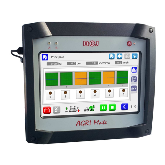
Page 69: Home
Value in km/h Here you can see the real time system speed, as detected by the set speed sensor. Row exclusion and Seeding Tab. Summary information Tab Synoptic Tab. h:min It shows the set time - 3.28 - PCS 200 Kit... - Page 70 PCS 200 Kit - 3.29 -...
-
Page 71: Rows Exclusion
Yellow row switched off through the row exclusion button row alarm/error Grey excluded row (not active) Value in cm Tramline button: active row row off excluded row (this button is not active) - 3.30 - PCS 200 Kit... -
Page 72: Summary Information About The Seeding Job
Seeding job starting date and time Seeding job date and time Time worked Tags related to the seeding job name Average working speed in [km/h] Maximum working speed in [km/h] Total ha-counter of the machine PCS 200 Kit - 3.31 -... -
Page 73: Synoptic Tab
Status icons micro-granulator A The icon color indicates the device status. Status icons micro-granulator B The icon color indicates the device status. If pressed, the devices icons, allow to access the diagnostics, setting, activation/deactivation pop-up windows. - 3.32 - PCS 200 Kit... - Page 74 By pressing this button, a Setup menu window is opened (see chapter SEEDING/SETTINGS), corresponding to the selected seeding discs. This button closes the window This button enables/disables the device Navigation buttons allowing to select the device you want to operate on PCS 200 Kit - 3.33 -...
- Page 75 The elements 4 and 6 on the machine will be lifted, as to ensure a 75cm row distance between elements 3 and 5 and elements 5 and 7. 75 cm 75 cm 75 cm 75 cm 75 cm 75 cm - 3.34 - PCS 200 Kit...
- Page 76 In case of changes, the settings will remain valid for all devices of the same type. This button closes the window This button enables/disables the device Navigation buttons allowing to select the device you want to operate on PCS 200 Kit - 3.35 -...
-
Page 77: Seeding Job
After a seeding job is closed, a number of information about the finished job is saved in the internal memory. A status window indicates this activity. As soon as the status window closes, it will be possible to start a new job. - 3.36 - PCS 200 Kit... -
Page 78: Alarms
It is possible to go on 3 seconds seeding but the operator should be aware of the situation. The already checked (acknowledgment button pressed) but still active errors, will be visualized in the window in a lighter background colour. PCS 200 Kit - 3.37 -... - Page 79 User Manual Field Description Alarm code Alarm description Alarm category Alarm acknowledgment button Active alarm which has already been acknowledged (grey text) - 3.38 - PCS 200 Kit...
- Page 80 Not possible to set that combination of parameters 2500 Group A parameters mismatch (number of disk holes, seeding distance) Not possible to set that combination of parameters 2501 Group B parameters mismatch (number of disk holes, seeding distance) PCS 200 Kit - 3.39 -...
- Page 81 Cycle power of the system from battery 1xx10 Overspeed error disconnect. Contact supplier if not solved Check CAN cable connection between ECU 1xx11 Heart beat ECU missing and DMD. Check supply cable to ECU. Check - 3.40 - PCS 200 Kit...
- Page 82 Cycle power of the system from battery disconnect. 1-1xx14 Pwm control volt Contact supplier if not solved. Cycle power of the system from battery disconnect. 1-1xx15 Position control error Contact supplier if not solved. PCS 200 Kit - 3.41 -...
- Page 83 1-1xx84 Prefill not completed and seeds are present in the hopper. 1 This is the same message as for 1-1xx81 alarm, but in this case there is a consecutive missing doublets situation (for ex. empty hopper). - 3.42 - PCS 200 Kit...
-
Page 84: Software Update And Protocol Change
Where applicable, you can perform the update in the following order: 1) ECU 2) HMI 3) DMD Protocols function allows to switch from the ROJ machine (therefore from the “ ” ECU system with standard HMI Agrimate), to the ISOBUS ARAG systems, controlled by a proprietary control unit called iBX100 Planter “... - Page 85 It allows to update the HMI software It allows to update the ECU board software It allows to update the motors software It allows to update the PSB for the HMI (only ROJ service) - 3.44 - PCS 200 Kit...
- Page 86 How to confirm the addressing and restore parameters 1. Close the alarms window via the green check mark. The MD Addressing “ ” opens. 2. Wait 10 seconds before pressing the Addressing button. “ ” PCS 200 Kit - 3.45 -...
- Page 87 8. Select the (PAR_<date_time>) file. If one or more files are present, select the most recent one. 9. Press Load . If the loading has been successful, the Parameters loaded “ ” “ ” message will be displayed indicating that the parameters have been correctly restored. - 3.46 - PCS 200 Kit...
- Page 88 HMI software update Path: Selecting the desired SW from the list and pressing the button it is possible to update the HMI. After the update the console shuts off automatically and the system reboots. PCS 200 Kit - 3.47 -...
- Page 89 (and therefore the elements: seeding unit, fertilizers or micro-granulators) to be updated. If you press the button after the selection, the selected MDs update starts. - 3.48 - PCS 200 Kit...
- Page 90 Field Description It allows to switch from the ROJ machine to the ARAG machine. Through this action all MDs will be assigned an address 7F. It allows to switch from the ARAG machine to the ROJ machine. Through this action all MDs will be assigned an address 20.
-
Page 91: Statistics
Path: Field Description Chart function (only accessible by ROJ Service) Statistics relative to the seeding elements. Distributors statistics (fertilizer spreader and micro-granulators) System events log Events and statistics storage - 3.50 -... - Page 92 Average Average population referred to the active seeding job. population (total) [seeds/ha] Partial [ha] Partial ha-counter (it is reset at the beginning of each new seeding job) Total [ha] Partial ha-counter for the machine PCS 200 Kit - 3.51 -...
- Page 93 Description Quantity [kg] Quantity of product spread during the active seeding job Partial [ha] Partial ha-counter (it is reset at the beginning of each new seeding job) Total [ha] Partial ha-counter for the machine - 3.52 - PCS 200 Kit...
- Page 94 Field Description Event time and date Unique identifier for the seeding job Event name and icon Detailed event description Press this button to save the Event Log (you will need a USB stick) PCS 200 Kit - 3.53 -...
- Page 95 The above procedure will create on the USB stick a directory called gt4_<nnnnn> containing some files. It is possible to send this directory to the Technical Support via email. <nnnn> is the identification number of the used HMI. - 3.54 - PCS 200 Kit...
-
Page 96: Terminal
To set up the day/night backlight levels. The slider controls allow to independently adjust the light levels in case of day/night setup. To select the night light slider control, tick the Night view check mark. “ ” PCS 200 Kit - 3.55 -... - Page 97 Home screen. Here it is possible to enable and set up the screensaver function delay: If enabled, in case of activity, the screen backlight is reduced to a minimum. - 3.56 - PCS 200 Kit...
- Page 98 In this page it is possible to regulate the sound intensity of the console built-in buzzer. The values range from 50 to 1000. A check mark on Legacy Buzzer allows you to make the updated software “ ” compatible with the old console hardware versions. PCS 200 Kit - 3.57 -...
-
Page 99: Test
Acceleration field. If it s unselected, the speed will start to decrease until the 0 value is ’ reached, following the deceleration ramp as specified in the Acceleration field. Current speed - 3.58 - PCS 200 Kit... - Page 100 Torque and speed chart window. The torque value is expressed in cNm and the speed in Hz. A check mark on % allows to see the Torque and Speed values expressed in percentage with reference to the maximum torque and speed. PCS 200 Kit - 3.59 -...
- Page 101 This test mode is only available when the seeding job is inactive or paused. Field Description The selected MDs start All MDs start All MDs are stopped Tractor speed expressed in km/h Motors selection window. - 3.60 - PCS 200 Kit...
- Page 102 User Manual This page is intentionally left blank PCS 200 Kit - 3.61 -...
-
Page 103: Maintenance And Troubleshooting
– GENERAL INFORMATION ABOUT MAINTENANCE Thanks to the inherent sturdiness of the PCS 200 system components, it is not required to carry out any particular preventive maintenance operations. However, in order to ensure the maximum equipment reliability and to avoid hazardous conditions, it is advisable to strictly follow the instructions and warnings given below. - Page 104 At the beginning of each season This control can be carried out by putting the motors into service through the test functions described in paragraph 3.11 and verifying that, when each MD safety switch opens, the motor is stopped - 4.2 - PCS 200 Kit...
-
Page 105: Spare Parts
Maintenance and Troubleshooting SPARE PARTS PCS 200 Kit - 4.3 -... - Page 106 Ref. on wiring diagram 54T01068 PCS200 ECU 58G00074 HMI GT4 AGRIMATE 1.406.601 PCS MD-O 54T01099 DMD2 MOTOR 4.5Nm 80 RPM LED (ROJ) 56C00646 PCS SDB 12+12 56C00651 PCS SDB 3+3 05R01310 B- / BAT- CABLE 05R01311 B+ / BAT+ CABLE...
- Page 107 Maintenance and Troubleshooting 14A00072 BATTERY INSULATORS (BORDEAUX NUTS) 05R01385 CAN TERMINATION (MOLEX ) SDB PCS 200 Kit - 4.5 -...
-
Page 108: Procedure For The Md Replacement Or Exchange
8. Close the safety switch of the new MD to address the device. 9. Once the addressing has been completed, press the Exit button. “ ” - 4.6 - PCS 200 Kit... - Page 109 13. The icon corresponding to the other MD starts flashing indicating that it has to be addressed. 14. Close the MD safety switch on the correct position to address the device. 15. Once the addressing has been completed, press the Exit button. “ ” PCS 200 Kit - 4.7 -...
- Page 110 9. Press a device icon to open the Unaddress MD window and select “ ” “ ” 10. Go on addressing all the machine with the new configuration. 11. Once the addressing has been completed, press the Exit button. “ ” - 4.8 - PCS 200 Kit...
- Page 111 Maintenance and Troubleshooting This page is intentionally left blank PCS 200 Kit - 4.9 -...
- Page 112 DISTRIBUTOR ISO 9001 Certificates by DNV from 1996 ISO 9001:2008 Certificates in 2009 Via Vercellone 11 13900 Biella (BI) Tel. +39 015 84 80 111 Fax +39 015 84 80 209 E-mail: comm@roj.com www.roj.it REV. 2.0 I 03/2016 –...
Need help?
Do you have a question about the PCS 200 and is the answer not in the manual?
Questions and answers