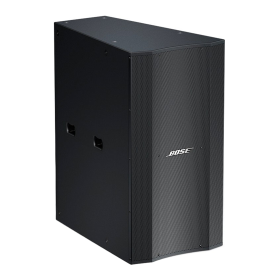
Bose Panaray LT 3202 III Service Manual
Hide thumbs Also See for Panaray LT 3202 III:

Advertisement

Quick Links

®
Panaray
LT Model
®
®
TM
®
3202
III, 4402
III, 9402
III, 9702
III,
MB24 III and MB12 III Loudspeakers
Service Manual
©2006 Bose Corporation
Reference Number 275484-SM Rev. 03

Advertisement

Table of Contents
loading

Summary of Contents for Bose Panaray LT 3202 III

  • Page 1 ® Panaray LT Model ® ® ® 3202 III, 4402 III, 9402 III, 9702 III, MB24 III and MB12 III Loudspeakers Service Manual ©2006 Bose Corporation Reference Number 275484-SM Rev. 03...
  • Page 2: Table Of Contents

    To prevent warranty infractions, refer servicing to warranty service stations or factory service. WARRANTY INFORMATION The Bose Panaray LT Model 3202, 4402, 9402, 9702, MB24 and MB12 Series III Loudspeakers are covered by a 5-year transferable limited warranty. PROPRIETARY INFORMATION...
  • Page 3: Specifications

    SPECIFICATIONS MECHANICAL External dimensions, single speaker ® 9702 III: 42.2" H x 22.5" W x 18.0" D (1072 x 572 x 368 mm) 9402 34.6" H x 22.5" W x 23.7" D (879 x 572 x 604 mm) III: ® 4402 34.0"...
  • Page 4 SPECIFICATIONS ELECTRICAL (Continued) Maximum sound pressure level (dB SPL) - pink noise per IEC 268-5 9702 III: Mid 127, High 123, Passive 126 9402 III: Mid 128, High 125, Passive 128 4402 III: Mid 126, High 128, Passive 130 3202 III: Mid 132, High 130, Passive 135 MB24 III: Parallel Mode 123, Discrete Mode 123...
  • Page 5: Product Description

    PRODUCT DESCRIPTION The Bose ® Panaray ® LT Series III Loudspeakers are designed to provide quality sound in ven- ues where speaker-to-listener distance, room reverberation time, ambient noise and high SPL requirements are key factors. Typical installations include performing arts facilities, theaters, auditoriums, houses of worship, stadiums and arenas.
  • Page 6: Packing List, Panaray

    Triangle Paper LT3202-III-5-107 Carton Loudspeaker, Model 3202 III 275484 LT3202 III (not included with carton kit) LT3202-III-5-104 PE Bag, 1850x1430x0.3 Owner's Guide, Models 3202, 276859 LT9702-III-5-108 4402, 9402 and 9702 III Figure 1. Panaray LT 3202 III Loudspeaker Packaging View...
  • Page 7 PACKING LIST Panaray ® LT 4402 ® III Loudspeaker ® Item Description Bose Vendor Part Number Note Number Part Number Kit, Carton, Model 4402 III, 276856 includes: LT4402-III-5-103 PP Cover Triangle Paper LT4402-III-5-102 PP Foam Middle LT4402-III-5-106 LT4402-III-5-101 Triangle Paper...
  • Page 8 PACKING LIST Panaray ® LT 9402 III Loudspeaker ® Item Description Bose Vendor Part Number Note Number Part Number Kit, Carton, Model 9402 III, 276857 includes: LT9402-III-5-105 PP Cover LT9402-III-5-101 Triangle Paper PP Foam Middle LT9402-III-5-106 Carton LT9402-III-5-107 Loudspeaker, Model 9402 III...
  • Page 9 PACKING LIST Panaray ® LT 9702 ® III Loudspeaker ® Item Description Bose Vendor Part Number Note Number Part Number Kit, Carton, Model 9702 III, 276858 includes: LT9702-III-5-104 PP Cover LT9702-III-5-101 Triangle Paper PP Foam Middle LT9702-III-5-105 Carton LT9702-III-5-106 Loudspeaker, Model 9702 III...
  • Page 10 PACKING LIST Panaray ® LT MB24 III Bass Loudspeaker ® Item Description Bose Vendor Part Number Note Number Part Number Kit, Carton, Model MB24 III, includes: PE Bag, 1600 x 1160 x 0.1mm LTMB24-III-2-104 PE Bag, 240 x 350 x 0.1mm...
  • Page 11 PACKING LIST ® Panaray LT MB12 III Bass Loudspeaker ® Item Description Bose Vendor Part Number Note Number Part Number Kit, Carton, Model MB24 III, includes: Paper Cover, LTMB12-III-2-103 774x636x107mm Cushioning Material, LTMB12-III-2-102 770x632x100mm Manual, Users 278247 BOSE/LT_MB12 PE Bag, 1200x1260x0.04mm...
  • Page 12: 3202 ® Iii Loudspeaker

    MAIN PART LIST Panaray ® LT 3202 ® III Loudspeaker (see Figure 7) Item Description Part Number Note Number Black White Logo, Panaray LT Kit, Grille Screw, TA4x15 (14 screws per kit) 297502 297503 Cap, Spring Spring, Logo Clip, Retaining, Logo Grille Assembly, includes screws, tape, logo, 298171 298556...
  • Page 13 MAIN PART LIST Panaray ® LT 4402 ® III Loudspeaker (see Figure 8) Item Description Part Number Note Number Black White Grille Assembly, includes: 297521 298580 screws, tape, logo, fastener and spring Gasket, Grille (consists of three sections) Kit, Grille Screw, TA4x15 (14 screws per kit) 297502 297503 Gasket, Compression Driver...
  • Page 14 MAIN PART LIST Panaray ® LT 9402 III Loudspeaker (see Figure 9) Item Description Part Number Note Number Black White Kit, Grille Screw, TA4x15 (14 screws per kit) 297502 297503 Logo, Panaray LT Grille Assembly (includes screws, tape, logo, 297525 298584 fastener and spring) Cap, Spring...
  • Page 15 MAIN PART LIST Panaray ® LT 9702 ® III Loudspeaker (see Figure 10) Item Description Part Number Note Number Black White Grille Assembly (includes: screws, tape, logo, 297527 298586 fastener and spring) Kit, Grille Screw, TA4x15(14 screws per kit) 297502 297503 Clip, Retaining, Logo Spring, Logo...
  • Page 16 MAIN PART LIST Panaray ® LT MB24 III Bass Loudspeaker Item Description Part Number Note Number Black White Gasket, Grille, MB24 Bass Module Grille Assembly, includes screws, logo, tape, 297514 298561 fastener and spring Logo Kit, includes tape, fastener and spring 276848 297505 Grille Screw Kit (14 screws)
  • Page 17 MAIN PART LIST Panaray ® LT MB12 III Bass Loudspeaker Item Description Part Number Note Number Black White Gasket, Grille, MB12 Bass Module Grille Screw Kit (14 screws) 297502 297503 Grille Assembly, (includes screws and logo) 296721 298588 Logo Kit, includes tape, fastener and spring 297504 297505 Screw, Woofer...
  • Page 18: Loudspeaker

    DISASSEMBLY PROCEDURES ® CAUTION: The rear of the Panaray 4. VEE Two Assembly Removal loudspeakers can become extremely hot during normal use. Do not attempt to service 4.1 Remove the four screws that secure the the loudspeakers until they have cooled to assembly to the cabinet.
  • Page 19: Tm Iii Loudspeaker (See Figure 9)

    DISASSEMBLY PROCEDURES 3. Compression Driver Removal 2. Logo Removal 3.1 Remove the twelve screws (13) that 2.1 Remove the grille using procedure 1 secure the rear panel (12) to the cabinet. Lift above. off the rear panel. The gasket should remain adhered to the cabinet.
  • Page 20: Loudspeaker (See Figure 10)

    2. Place the VEE Two assembly on a flat surface so that the aluminum casting with Note: Refer to Figure 10 for the following the Bose logo is facing upward. procedures. 3. Using a Phillips-head screwdriver, remove 1. Grille Removal all of the screws around the perimeter of the casting.
  • Page 21: Test Procedures

    TEST PROCEDURES 3. Input Panel Removal Panaray ® LT Model 3202 ® , 4402 ® , 9402 ® and 9702 Series III Loudspeakers 3.1 Using a Phillips-head screwdriver, re- move the 8 screws that secure the input Note: Ensure that the speaker under test panel to the enclosure.
  • Page 22: Loudspeaker Wiring Diagrams

    TEST PROCEDURES Model MB24 and MB12 Series III Bass 1.2 No extraneous noise such as rubbing, Loudspeakers scraping or ticking should be heard. Note: For the MB24, ensure that the speaker 2. Phase Test under test is in PARALLEL mode for the following tests.
  • Page 23 Loudspeaker Wiring Diagrams EAG011-01 V1.1 Biamped 6UF/250V 3UF/250V Connector 0.72mH/1.3mm 8981 5.08mm4P Passive T1.4hp HIGH-FREQUENCY DRIVER MID-FREQENCY DRIVERS 4.5' 4.5' 4.5' 4.5' Model 4402 ® , 9402 and 9702 ® Series III Wiring Diagram EAG013-01 1-01 Connector 8981 5.08mm4P Model MB24 Series III Bass Loudspeaker Wiring Diagram...
  • Page 24: Accessories Used With The Panaray Lt Series Iii Loudspeakers

    Loudspeaker Wiring Diagrams EAG013-01 1-01 Model MB12 Series III Bass Loudspeaker Wiring Diagram ® Accessories Used With the Panaray LT Series III Loudspeakers Panaray Digital Controller The Panaray System Digital Controller has a universal power suppy for worldwide use. Variants of the product refer to the AC cord included with the product.
  • Page 25: High Frequency Compression Driver Diaphragm Replacement Procedure

    High Frequency Compression Driver Diaphragm Replacement Procedure The compression driver diaphragm is replaceable using a kit, part number 181470 or 276861. Perform the steps below. 1. Remove the compression driver using the disassembly procedures for the Panaray ® speaker you are repairing. 2.
  • Page 26: Service Manual Revision History

    SERVICE MANUAL REVISION HISTORY Date Revision Description of Change Change Driven Pages Level Affected 4/04 Document released at revision 00. Service manual initial release 12/04 Packaging part number and exploded view Vendor 4-17 changes. 10/05 1. Added new compression driver and Part number Various replacement diaphragm part numbers.
  • Page 27 SPECIFICATIONS AND FEATURES SUBJECT TO CHANGE WITHOUT NOTICE Bose Corporation The Mountain Framingham Massachusetts USA 01701 Reference Number 275484-SM Rev. 03; 9/2006 (P) http://serviceops.bose.com...

Table of Contents