
Related Manuals for Nidek Medical CP-770


Summary of Contents for Nidek Medical CP-770
- Page 1 CHART PROJECTOR CP-770 Model SERVICE MANUAL September 2007 Pages in total: 64 MCP8**RDA001A/E...
- Page 2 NIDEK CO., LTD. : 34-14, Maehama, Hiroishi-cho, Gamagori, Aichi 443-0038, Japan (Manufacturer) Telephone: (81-533) 67-6611 Facsimile: (81-533) 67-6610 NIDEK CO., LTD : 3F Sumitomo Fudosan Hongo Bldg., 3-22-5, Hongo, (Tokyo Office) Bunkyo-Ku, Tokyo 113-0033, Japan Telephone: (81-3) 5844-2641 Facsimile: (81-3) 5844-2642 NIDEK INCORPORATED : 47651 Westinghouse Drive, Fremont, California 94539, U.
-
Page 3: Table Of Contents
4.2.6 The VA 0.05 chart is not displayed..............4-5 4.3 The CP-770 cannot be Operated with the Remote Control........4-6 4.4 The Chart is not Displayed Properly by Operating the CP-770 with the Remote Control......................4-7 4.5 The Chat is Out of Focus..................4-8 4.6 The Chart Brightness is Inappropriate. - Page 4 6.1.6.1 Replacing the mask motor ASSY............6-3 6.1.6.2 Replacing the chart motor ASSY............6-4 6.2 Replacing the Main Board ..................6-5 6.3 Replacing the Cable Assemblies ................6-6 6.3.1 Replacing the switch cable ................6-6 6.3.2 Replacing the WR cable .................6-7 6.3.3 Replacing the chart LED .................6-7 6.3.4 Replacing the disc sensors ................6-8 6.3.4.1 Replacing the mask disc sensor ............6-8 6.3.4.2 Replacing the chart disc sensor ............6-8...
-
Page 5: Introduction
Model CP-770. For proper service, be sure to understand this manual thoroughly before servicing. Refer to the Chart Projector CP-770 Operator’s Manual and Parts List. Refer to the Service Manual Annex for important changes. In case the device can not be repaired according to the procedures described in this manual, please report the serial number of the device and details of the symptom or symptoms. - Page 6 MCP8**RDA001A This page is intentionally left blank. 1 - 2...
-
Page 7: Precautions
• If malfunction occurs, check the symptom and turn the power off. • Do not drop parts and screws inside the CP-770 and take care not to bump the CP-770. • Prepare a case for storing the screws and parts in order not to lose them. - Page 8 MCP8**RDA001A/E <Precautions for adjustment> • Service at a stable and level surface free from vibration. Tilting or vibration can prevent normal adjustment. • Do not use the adjustment tools for other than the purpose described in this manual. 2 - 2...
-
Page 9: Troubleshooting
Does the pilot lamp light up? 4.1 The Pilot Lamp does not Light up. Does initialization finish properly? 4.2 Initialization does not Finish Properly. Can the CP-770 be operated with the remote 4.3 The CP-770 cannot be Operated with the control? Remote Control. - Page 10 MCP8**RDA001A/E This page is intentionally left blank. 3 - 2...
-
Page 11: Subtroubleshouting
MCP8**RDA001A/E § 4 SUB-TROUBLESHOUTING 4.1 The Pilot Lamp does not Light Up. Is the power voltage appropriate? Use an appropriate voltage outlet. Are there any breaks in the cable switch (34801- Replace the cable switch (34801-EA01). EA01)? Are there any breaks in the primary cable (34801- Replace the primary cable (34801-EA03). -
Page 12: Initialization Does Not Finish Properly
MCP8**RDA001A/E 4.2 Initialization does not Finish Properly. Does the chart disc motor run? 4.2.1 The chart disc motor does not run. Does the mask disc motor run? 4.2.2 The mask disc motor does not run. 4.2.3 The chart disc motor does not stop running Does the chart disc motor stop running properly? properly. -
Page 13: The Chart Disc Motor Does Not Run
MCP8**RDA001A/E 4.2.1 The chart disc motor does not run. Are there any breaks in the chart disc motor Replace the chart motor ASSY. (34801-1610). (34801-E004)? (See 6.1.6.2.) Replace the main board (34801-BA01). (See 6.2.) Is the symptom improved? Completion Replace the chart motor ASSY. (34801-1610). (See 6.1.6.2.) 4.2.2 The mask disc motor does not run. -
Page 14: The Chart Disc Motor Does Not Stop Running Properly
MCP8**RDA001A/E 4.2.3 The chart disc motor does not stop running properly. When the P11 (J11) connector on the main board (34801-BA01) is disconnected, is the voltage Replace the main board (34801-BA01). b e t w e e n t h e 1 s t a n d 2 n d p i n s o f t h e J 1 1 (See 6.2.) connector DC + 5 V? The chart sensor (34801-EA08) is shaded, is the... -
Page 15: The Lamp Does Not Light Up
MCP8**RDA001A/E 4.2.5 The lamp does not light up. Disconnect the P2 (J2) connector on the main board (34801-BA01), and attach the new chart LED (34801-EA07). Replace the main board (34801-BA01) Does the chart LED (34801-EA07) light up? (See 6.2.) Replace the chart LED (34801-EA07). (See 6.3.3.) 4.2.6 The VA 0.05 chart is not displayed. -
Page 16: The Cp-770 Cannot Be Operated With The Remote Control
MCP8**RDA001A/E 4.3 The CP-770 cannot be Operated with the Remote Control. Are there any obstructions between the remote control and the receiving window of the main Remove the obstruction. body? Match the channel settings of the remote control Do the channel settings of the remote control and and the main body. -
Page 17: The Chart Is Not Displayed Properly By Operating The Cp-770 With The Remote Control
MCP8**RDA001A/E 4.4 The Chart is not Displayed Properly by Operating the CP-770 with the Remote Control. Does the chart type of the remote control Use the remote control corresponding with the correspond with the chart of the CP-770 main chart of the CP-770 main body. -
Page 18: The Chat Is Out Of Focus
MCP8**RDA001A/E 4.5 The Chat is Out of Focus. Is the installation position of the main body as Install the main body on the position as described specified? in the standard. Adjust the focus and the chart size. (See 7.11.) Is the symptom improved? Completion Is there any dust on the chart ASSY.? Clean the chart ASSY. -
Page 19: The Chart Brightness Is Inappropriate
MCP8**RDA001A/E 4.6 The Chart Brightness is Inappropriate. Set SW5 on the main board (34801-BA01) to Does the SW5 setting on the main board (34801- correspond with the refraction distance. BA01) correspond with the refraction distance? (See 7.10.) Set SW7 on the main board (34801-BA01) to Does the SW7 setting on the main board (34801- correspond with the setting distance. -
Page 20: The Chart Brightness Is Uneven
MCP8**RDA001A/E 4.7 The Chart Brightness is Uneven. Is there any dirt on the screen or is the screen Replace the screen. discolored? Is the brightness on the same chart irregular? Clean the chart ASSY. (See 7.7.) Is there any dirt on the lens of the C lens ASSY. Clean the C lens ASSY.(34801-1201). -
Page 21: The Chart Does Not Appear Properly When Looking At Polarized Chart Through The Polarizing Glasses
MCP8**RDA001A/E 4.8 The Chart does not Appear Properly When Looking at Polarized Chart through the Polarizing Glasses. Is the main body tilted? Install the main body on a level surface. Is the projected chart tilted? Adjust the initial position. (See 7.3.) Is the refractor used as the check instrument for Replace the chart ASSY. - Page 22 MCP8**RDA001A/E This page is intentionally left blank. 4 - 12...
-
Page 23: Removing Procedure
MCP8**RDA001A/E § 5 REMOVING PROCEDURE 5.1 Removing the Upper Cover 1. Remove the cap (32105-M730) and PC3×6 unscrew PC3 x 6. 2. Remove the upper cover ASSY. (34801- 1520) by moving it slightly to the direction of the arrow while holding up the rear part of the front cover ASSY. -
Page 24: Removing The Bottom Cover
MCP8**RDA001A/E 5.3 Removing the Bottom Cover 1. Remove the upper cover (34801-1520). (See 5.1.) 2. Remove the front cover (34801-1510). BS3×6 (See 5.2.) 3. Unscrew BS3 x 6 (n = 5), and remove the bottom cover (34801-M153). 4. Reassemble the removed parts in reverse order. -
Page 25: Replacement
MCP8**RDA001A/E § 6 REPLACEMENT 6.1 Replacing Assemblies 6.1.1 Replacing the illumination ASSY. Replacement part: 34801-1200 (Type G, Type M, Type T, Type PhM) : 34801-1210 (Type UK) 1. Remove the cover. (See 5.1, 5.2 and 5.3.) 2. Disconnect the P2 (J2) connector on the main board (34801-BA01). -
Page 26: Replacing The Zooming Lens Assy
MCP8**RDA001A/E 6.1.3 Replacing the zooming lens ASSY. Replacement part: 34801-1310 1. Remove the cover. (See 5.1, 5.2, 5.3.) HH3×4 2. Loosen HH3 x 4 (n = 2), and remove the zooming lens ASSY. (34801-1310). 3. Unscrew SB3 x 4, and remove the zooming lens ASSY. -
Page 27: Replacing The Motor Assy
MCP8**RDA001A/E 6.1.6 Replacing the motor ASSY. 6.1.6.1 Replacing the mask motor ASSY. Replacement part: 34801-1610 1. Remove the cover. (See 5.1, 5.2 and 5.3.) 2. Unscrew BS3 x 6, and remove the shield plate (34801-M045). 3. Remove the disc cover. (See 5.4.) BS3×6 4. -
Page 28: Replacing The Chart Motor Assy
MCP8**RDA001A/E 6.1.6.2 Replacing the chart motor ASSY. Replacement part: 34801-1610 1. Remove the cover. (See 5.1, 5.2, 5.3.) 2. Disconnect the P1 (J1) and P4 (J4) connectors on the main board (34801- BA01). 3. Unscrew SB3 x 4. 4. Unscrew SB3 x 6 (n = 6), and remove the SB3×4 main board (34801-BA01) with the base plate (34801-M001) from the disc house... -
Page 29: Replacing The Main Board
MCP8**RDA001A/E 6.2 Replacing the Main Board Replacement part: 34801-BA01 1. Remove the cover. (See 5.1 and 5.2.) BS3×6 2. Disconnect the all connectors on the main board (34801-BA01). 3. Unscrew BS3 x 6 (n = 4), and replace the main board (34801-BA01). 4. -
Page 30: Replacing The Cable Assemblies
MCP8**RDA001A/E 6.3 Replacing the Cable Assemblies 6.3.1 Replacing the switch cable Replacement part: 34801-EA01 1. Remove the cover. (See 5.1, 5.2 and 5.3.) 2. Remove the switch cable (34801-EA01) from the inlet (80457-00085) of the inlet ASSY. (34801-1600). EA01 3. Unscrew BS3 x 6 (n = 2), and remove the switch cable (34801-EA01) and switch EA01 EA03... -
Page 31: Replacing The Wr Cable
MCP8**RDA001A/E 6.3.2 Replacing the WR cable Replacement part: 34801-EA06 1. Remove the cover. (See 5.1, 5.2 and 5.3.) 2. Disconnect the P4 (J4) connector on the main board (34801-BA01). 3. Unscrew PC2.6 x 5 (n = 2), and replace the WR cable (34801-EA06). -
Page 32: Replacing The Disc Sensors
MCP8**RDA001A/E 6.3.4 Replacing the disc sensors 6.3.4.1 Replacing the mask disc sensor Replacement part: 34801-EA08 1. Remove the cover. (See § 5.) EA08 CK2.6×4 2. Disconnect the P10 (J10) connector on the main board (34801-BA01) 3. Unscrew CK2.6 x 4, and replace the disc sensor (34801-EA08). -
Page 33: Replacing The Switching Power Supply For Medical Devices
MCP8**RDA001A/E 6.4 Replacing the Switching Power Supply for Medical Devices Replacement part: 34801-E001 1. Remove the cover. (See 5.1, 5.2 and 5.3.) BS3×6 2. Disconnect the all connectors on the E001 switching power supply for medical devices (34801-E001). 3. Unscrew BS3 x 6 (n = 4), and replace the switching power supply for medical devices (34801-E001). - Page 34 MCP8**RDA001A/E This page is intentionally left blank. 6 - 10...
-
Page 35: Adjustment
MCP8**RDA001A/E § 7 ADJUSTMENT 7.1 Checking the Version No. 1. Remove the cover. (See 5.1.) 2. Turn on the system power. 3. After initialization is finished, press any of the center, left or right of SW3 on the main LED SW5 board. -
Page 36: Setting Sws On The Main Board
MCP8**RDA001A/E 7.2 Setting SWs on the Main Board 1. Set DIP SW2 as follows. Type No.(*) Factory setting Chart type Depending on the chart type Forced reset of the program (Changed back to the factory setting.) Must OFF Self-check of the cable communication line and continuous driving mode Brightness adjustment mode Chart and mask disc adjustment mode... -
Page 37: Adjusting The Initial Position With The Remote Control
MCP8**RDA001A/E 7.3 Adjusting the Initial Position with the Remote Control 1. Remove the cover. (See 5.1.) 2. Turn on the system power. 3. Set No. 8 of DIP SW2 on the main board (34801-BA01) to the ON position. 4. Adjust the initial positions of the chart and open mask by operating the remote control as follows: (1) When the chart and mask are largely blocked, adjust them by pressing the program BACK button to switch to the coarse adjustment mode. -
Page 38: Adjusting The Led Assy. Position
MCP8**RDA001A/E 7.4 Adjusting the LED ASSY. Position 1. Remove the cover. (See 5.1, 5.2 and 5.3.) 2. Turn on the system power. 3. Set the adjustment screw (34801-M097) on White paper the rear lens ASSY. and the front lens ASSY. on the zooming lens ASSY. -
Page 39: Adjusting The Mask Positions
MCP8**RDA001A/E 7.5 Adjusting the Mask Positions 7.5.1 Adjusting the mask ASSY. 1. Install the main body for the distance between the lens-barrel and the screen to be five meters. 2. Turn on the system power. 3. With the lens-barrel, adjust the projected chart size to be same as the test scale size. - Page 40 MCP8**RDA001A/E (2) The boundary of the Red-green filter is in center. Acceptable bounds: When projecting the chart five meters away, the center of the filter is within 3 mm from the center of the chart. GOOD (3) Light leakage (Projection to adjacent masks) does not occur. 5.
-
Page 41: Adjusting The Fixed Mask Position
MCP8**RDA001A/E 7.5.2 Adjusting the fixed mask position * When adjusting the mask positions, check them by the following procedures and adjust each of them if necessary. 1. When the visual acuity values are partly blocked while the visual acuity chart is displayed, loosen SB3 x 6 (n = 2) and adjust the illumination ASSY. - Page 42 MCP8**RDA001A/E 2) When the horizontal shadows are projected, loosen SB3 x 6 (n = 2) and adjust the illumination ASSY. (34801- 1210) position. Horizontal shadows 1210 SB3×6 3. If the illumination ASSY. (34801-1210) position is adjusted, check that shadows are not projected on the visual acuity values when the VA chart is displayed.
-
Page 43: Self-Checking The Main Board
MCP8**RDA001A/E 7.6 Self-Checking the Main Board 1. Remove the cover. (See 5.1.) 2. Set No. 6 of DIP SW2 on the main board (34801-BA01) to the ON position. LED SW5 3. Turn on the system power. 4. When set No.1 to 5 of SW2 on the main board (34801-BA01) to the ON or OFF position, check that the LED display on the main board becomes as follows. - Page 44 MCP8**RDA001A/E 10. When rotary SW7 is set to from 0 to 9, check the LED display on the main board becomes as follows. 1) When SW7 is set to 0, the LED display: 0 2) When SW7 is set to 1, the LED display: 1 3) When SW7 is set to 2, the LED display: 2 4) When SW7 is set to 3, the LED display: 3 5) When SW7 is set to 4, the LED display: 4...
-
Page 45: Cleaning
MCP8**RDA001A/E 7.7 Cleaning 1. Cleaning the chart ASSY. and mask ASSY. 1) Remove the disc cover. (See 5.4.) 2) Turn on the system power. 3) Disconnect the P7 (J7) and P6 (J6) connectors on the main board (34801-BA01). 4) Turn the mask disc and the chart disc with hands, and check that there are no dust and dirt on them. -
Page 46: Displaying Or Not Displaying The Visual Acuity Values
MCP8**RDA001A/E 7.8 Displaying or Not Displaying the Visual Acuity Value 1. Remove the cover. (See 5.1.) 2. Turn on the system power. 3. Loosen BS3 x 6, and adjust the VA mask BS3×6 (34801-M029) position as the following description. 1) Not to display the visual acuity values, move the VA mask (34801-M029) to the right side, and fasten BS3 x 6. -
Page 47: Setting The Remote Control Channels
MCP8**RDA001A/E 7.9 Setting the Remote Control Channels 1. Setting the remote control code 1) Remove the cover. ( See 5.1.) 2) Set SW6 on the main board (34801-BA01) as the following table. 2. Setting the remote control channel of the remote control 1) Remove the battery case cover. -
Page 48: Setting The Refraction Distance And The Chart Brightness
MCP8**RDA001A/E 7.10 Setting the Refraction Distance and the Chart Brightness 1. Remove the cover. (See 5.1.) 2. Turn on the system power. 3. Setting the refraction distance 1) Set rotary switch SW5 on the main board (34801-BA01) to the value indicated on the table according to the refraction distance. -
Page 49: Setting The Chart Size And The Focus
MCP8**RDA001A/E 7.11 Setting the Chart Size and the Focus 1. Remove the cover. (See 5.1.) 2. Turn on the system power. 3. Project the following chart on the screen. 1) Chart type G: 8 2) Chart type M, UK, T: E 4. -
Page 50: Setting The Brightness
MCP8**RDA001A/E 7.12 Setting the Brightness 1. Remove the cover. (See 5.1.) 2. Set No.7 of SW2 on the main board to the ON position. 3. Turn on the system power. LED SW5 4. Move SW3 on the main board to left or right, and set the LED display to be the same value as the label that indicates the brightness. -
Page 51: Information
MCP8**RDA001A/E § 8 INFORMATION 8.1 Wiring Diagram 8 - 1... -
Page 52: Connector Cable
MCP8**RDA001A/E 8.2 Connector Cable 34801-EA01 34801-EA02 34801-EA03 34801-EA04 8 - 2... - Page 53 MCP8**RDA001A/E 34801-EA06 34801-EA07 34801-EA08 8 - 3...
- Page 54 MCP8**RDA001A/E 34801-E004 8 - 4...
-
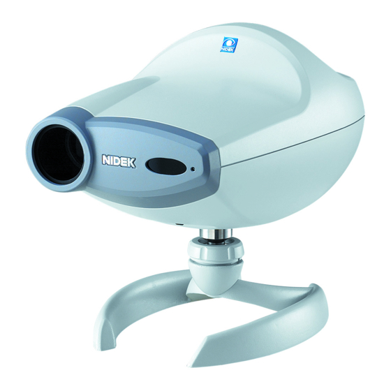
Page 55: View
MCP8**RDA001A/E 8.3 View Main body Upper cover screw Projection lens Remote control receiving window Pirot lamp Table stand (Optional) RT communication connector Power inlet Power switch 8 - 5... - Page 56 MCP8**RDA001A/E Remote control Remote control transmitter Lamp OFF/ON button Chart selection buttons (33 types) Red-green filtering button Single letter mask button/Function button Program (A, B, C) START buttons Sideward movement buttons (Vertical line mask) Horizontal line mask button Program NEXT button VA selection buttons (Horizontal line mask) Program BACK button...
-
Page 57: Label
MCP8**RDA001A/E 8.4 Label 8 - 7...
Need help?
Do you have a question about the CP-770 and is the answer not in the manual?
Questions and answers
characters are reversed
The characters may appear reversed on the Nidek Medical CP-770 if the chart or mask disc is not correctly aligned. This can happen due to incorrect adjustment of the illumination ASSY, chart ASSY, or mask position. Proper alignment and adjustment of these components are necessary to ensure the correct display of characters.
This answer is automatically generated
setup cp770 using mirrors