Advertisement
Quick Links
Advertisement

Subscribe to Our Youtube Channel
Related Manuals for Faber Triple Premium XXL

Summary of Contents for Faber Triple Premium XXL
- Page 1 Triple Premium XXL...
- Page 2 Installatie handleiding 2 < < < <...
- Page 3 Installatie handleiding 2.1 a 2.1 b 2.1 c 2.1 d 3 < < < <...
- Page 4 Installatie handleiding 4 < < < <...
- Page 5 Installatie handleiding 3.1 a 3.1 b 3.1 c 5 < < < <...
- Page 6 Installatie handleiding 5.1 a 5.1 b 5.1 c 5.1 d 5.1 e 6 < < < <...
- Page 7 CE Declaration Through the natural air circulation of the fire moisture and uncured volatile components Glen Dimplex Benelux certifies that this Faber fire from paint, building materials and carpeted complies with the essential requirements of the floors, etc. are attracted. These parts can gas appliances directive.
-
Page 8: Installation Requirements
Before the falls chimney breast can be placed, the flue materials specified by Faber. Only when installation box (on the same way the like the fire) using these materials can Faber guarantee the is placed level and in the correct position. - Page 9 Installatie handleiding Positioning of the fire 3.6.1 , Wall terminal. For a facade or wall outlet use a wall terminal. Take the installation requirements into account see (fig.4.1 C Chapter 3. Depending on the calculation this can be a diameter of 130/200mm or 100/150mm. Place the unit in the desired position and set the height and level of the fire with the adjustable legs 3.6.2...
-
Page 10: Removing The Front Glass
2.4). openings with a minimum free passage of 200cm2 If the reference points are not removed, the cover per opening in the space above the fire. Faber strips will not fit. supply grilles of the correct dimensions or a similar alternative may be used. - Page 11 Installatie handleiding 6.1.1 Glow wire Place the suction cups on the glass. Draw the sealing cord and the glass clip out The “glow wire” gives a decorative glow effect. the slot. (fig.5.1 a). Slide the glass to the top so that the bottom is Pull the wire well apart and place tufts in different released from the slot.
- Page 12 Installatie handleiding Check that ignition of the main burner goes Connect your meter on the measure point smoothly and quietly B(see fig. 1.7) With the remote you can control the fire to the Open the gas tap/isolator ...
- Page 13 Handing over to the customer whether your chosen flue configuration is possible in combination with your fire, is to use the free Installation instruction. “Faber Flue App” which can be download from: User manual. ITC operation instruction. Warranty card.
- Page 14 Installatie handleiding 90° bends which are used to switch from vertical to If the result is “x” or if the values are outside the horizontal or vice versa (Fig. 12.2 and 12.3 G, O and table, then the combination is not allowed. The TVH or THL can be adjusted to achieve a viable system.
- Page 15 Installatie handleiding 11.1 Table for pipe diameter 100/150mm Start length (STL) total Vertical height (TVH) and total Horizontal length(THL) 30.2 30.2 30.2 30.2 30.2 40.2 40.2 40.2 40.2 40.2 50.2 50.2 50.2 50.2 50.2 50.2 60.2 60.2 60.2 60.2 15 < <...
- Page 16 Installatie handleiding 11.2 Table for pipe diameter 200/130mm Start length (STL) total Vertical height (TVH) and total Horizontal length(THL) 30.4 30.4 30.4 30.4 40.4 30.4 30.4 40.4 40.4 40.4 30.4 30.4 40.4 40.4 40.4 40.4 30.4 30.4 50.4 50.4 40.4 40.4 40.4 30.4...
- Page 17 Installatie handleiding Example fig. 12.1 fig.1 2.2 fig 12.3 17 < < < <...
- Page 18 Installatie handleiding flue calculation table Starter Length (STL) first pipework component that is placed on the fire value Flue length from 0,1 - 0,45 m Flue length from 0,5 - 0,90 m Flue length from 1,0 - 1,40 m Flue length from 1,5 - 2,00 m Flue length from 2,00 m und mehr Bends 90°...
- Page 19 Installatie handleiding Total Vertical height (TVH) Measured height Rounded value Meter Meter Total Horizontal length (THL) Calculate Part number value result The total flue length of ½ m and 1 m pipes in meters 90° bends in the horizontal flue length 45°...
- Page 20 Installatie handleiding Is the found value “X” then the flue run is not possible Solution: change the TVH or THL If the STL value is less than as specified in the top row of the table , the flue run is not possible . Solution: starter length to low! see for the minimum length in the top row of the table Result Restrictor size = found value before the comma...
-
Page 21: Technical Data
Installatie handleiding Technical data Gascat. IIH3B/P IIH3B/P IIH3B/P Type appliance C11 C31 C11 C31 C11 C31 Reference gas Input 14.6 14.5 Output Efficiency class NOx class inlet-pressure mbar Gas rate at 15ºC and 1013 mbar 1.511 0.461 0.588 Gas rate at 15ºC and 1013 mbar gr/h 1180 1100... -
Page 22: Terminal Position
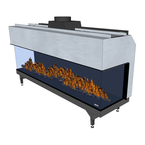
Installatie handleiding Terminal position. Please note: These rules apply only for the proper functioning of the unit, there may be additional requirements for ventilation and environmental protection that you will need to comply with in your country, e.g. Building Regulations in the UK. - Page 23 Installatie handleiding Drawings 16.1 Triple Premium XXL 23 < < < <...
- Page 24 Installatie handleiding 16.2 Builder’s opening and control box dimensions 24 < < < <...
- Page 25 Installatie handleiding 16.3 Builder’s opening and ventilation grills dimensions 25 < < < <...
Need help?
Do you have a question about the Triple Premium XXL and is the answer not in the manual?
Questions and answers