
Related Manuals for Chinowing T40

Summary of Contents for Chinowing T40
- Page 1 User Manual T40 Portable Ground Control Station (July, 2021) V 1.0.3 video&data&RC link V21 V30 V40 www.chinowing.com...
-
Page 2: Table Of Contents
7. T40 GCS Operation ................23 6.2 Split Screen Settings ..............22 7.1 Remote Control Power-on and Power-Off ....... 23 8. T40 GCS <Parameters Setting Software> Operation ......28 7.2 Indicator Instruction of GCS and Receiver ....... 24 8.1 <Parameters Setting Software> Instruction ......28 8.2 Channel Monitoring and Calibration ........ - Page 3 14. HID Controller Instruction ..............74 13.3 V30 Video Link Parameters ............ 73 15. Firmware Upgrading Operation Steps ..........77 15.1 T40 GCS Firmware Upgrade ........... 77 15.2 V21 Receiver Firmware Upgrade ..........80 16. Common Questions ................81 17. T40 Specification ................82...
-
Page 4: Disclaimer
2. Product Precautions T40 ground terminal is matched with airborne unit to use together. T40 can be matched with 3 different airborne units: V21, V30, V40. Frequency 800MHz, 1.4GHz and 2.4GHz for choice. Default: 1.4GHz. 800M 806 – 826MHz... -
Page 5: Installation Note
2.2 Precautions for Use 1) Before use, please make sure that all connection wires are fastened reliably and all components work normally. 2) Please open the <RC Configuration Software> and check whether the channels are normal. www.chinowing.com... -
Page 6: Product Introduction
It takes about 2.5hs to be fully charged. 3. Product Introduction T40 is all-in-one hand-held GCS that integrates remote control, data transmission module, video transmission module and industrial computer. High integration, dual screens display, dual SBUS output, easy operation. There are 20 physical channels and 7 virtual channels to map to any channel of SBUS. - Page 7 TNC ZYJB antenna*2 SMA ZYJB antenna*2 (For T40 remote control) (For V21 receiver) Fibre-glass epoxy antenna (TNC sucker*2, TNC fibre glass epoxy antenna*2) Cables Charger*1 Accessories (XT40 power cable*1; (DC16.8V, charging for RC) SBUS signal wire GH 3pin*2; TTL signal wire GH 4pin*1;...
-
Page 8: V30 Version
4.2 V30 Version T40 Remote Control*1 V30 Receiver Main module TNC ZYJB antenna*2 SMA ZYJB antenna*2 (For T40 remote control) (For V30 receiver) Fibre-glass epoxy antenna (TNC sucker*2, TNC fibre glass epoxy antenna*2) Cables Charger*1 Accessories (XT40 power cable*1; (DC16.8V 6V, charging for RC) SBUS signal wire GH 3pin*2;... -
Page 9: V40 Version
TTL signal wire GH 4pin*1) HDMI wire Aviation Plug 6pin (HDMI A to micro) 4.3 V40 Version T40 Remote Control*1 V40 Receiver Main module TNC ZYJB antenna*2 SMA ZYJB antenna*2 (For T40 remote control) (For V40 receiver) www.chinowing.com... - Page 10 Fibre-glass epoxy antenna (TNC sucker*2, TNC fibre glass epoxy antenna*2) Cables Charger*1 Accessories (XT40 power cable*1; (DC16.8v 6A, charging for RC) SBUS signal wire GH 3pin*2; TTL signal wire GH 3pin*1; GH 4pin*5) LAN-to-4Pin wire*1 HDMI-to-HDMI micro*1 Aviation plug 6pin www.chinowing.com...
-
Page 11: Product Instruction
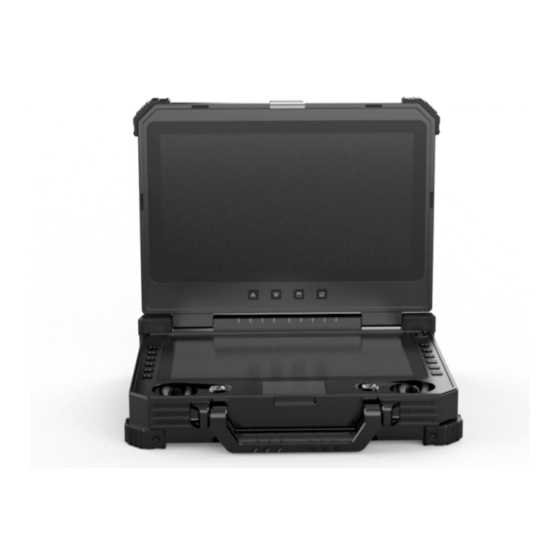
5. Product Instruction 5.1 T40 GCS 1.T40 副屏 2. 输出 SBUS 和 rs232 信号 3.网口 1. GCS main screen: the computer main interface display 2. GCS secondary screen: used for split screen and external input display 3. Power supply button and indicator: used for power-on and power-off the GCS 4. -
Page 12: V21 Receiver
23. USB, VGA, HDMI interfaces: used for SUB communication and video output 24. Antenna interface: corresponding to slave antenna 25. Antenna interface: corresponding to main antenna 5.2 V21 Receiver 5.2.1 V21 Receiver Indicator&Port Instruction Front view ① Data receiving indicator: light will flicker in the condition of data receiving. www.chinowing.com... - Page 13 Airborne unit: SBUS1 indicator will flicker when there is data output of SBUS1. ⑦SBUS2 indicator: Ground unit: SBUS2 indicator will flicker when there is data input of SBUS2. Airborne unit: SBUS2 indicator will flicker when there is data output of SBUS2. www.chinowing.com...
- Page 14 As shown in the above photo, connecting TTL port and S-Bus port of the V21 receiver to your device by lead wire of servo. TTL port SBUS port Receiver GND GND Flight control Receiver + + Flight control (or other device) - (or other device) www.chinowing.com...
-
Page 15: V30 Receiver
communicate. Be sure to use the specified type of antenna and install it correctly. It is forbidden to use other types of antennas. 5.3 V30 Receiver 5.3.1 V30 Receiver Indicator&Port Instruction Front view www.chinowing.com... - Page 16 ①Data transmission port: TTL level, in transparent transmission with the COM6 in the computer ②SBUS 1 port: used for connecting flight controller or payload ③SBUS 2 port: used for connecting flight controller or payload ④Power supply port: 7.4-12V ⑤HDMI video input interface: connecting camera www.chinowing.com...
- Page 17 3. As shown in the above photo, connecting COM port and S-Bus port of the V30 receiver to your device by lead wire of servo. TTL port SBUS port Receiver GND Flight control Receiver + + Flight control (or other device) - (or other device) www.chinowing.com...
-
Page 18: V40 Receiver
(CH1-CH16) channels from Remote Control. And SBUS1 and SBUS2 can be mapped separately. By default, the S-BUS1 and S-BUS2 interfaces output the CH1 to CH16 of the remote control to 1-16 channels. 5.4 V40 Receiver 5.4.1 V40 Receiver Indicator&Port Instruction www.chinowing.com... - Page 19 ⑩ CVBS video input interface CVBS video input ⑪ LAN port Used for transmit the video or read the V40 parameters ⑫ SBUS1 interface For Sbus1 signal output ⑬ SBUS2 interface For Sbus2 signal output ⑭ TTL port: Full-duplex serial port www.chinowing.com...
- Page 20 LINK indicator is always on, it means the successful connection. 4. When the COM indicator is on, it means that the serial module starts normally, and when the WORK indicator is on, it means that the self-test of the airborne www.chinowing.com...
-
Page 21: T40 Secondary Screen Instruction
6. T40 Secondary Screen Instruction T40, after power-on, the secondary screen is, by default, for the computer extension screen, the secondary screen for the computer extension screen when the upper screen can only use touch. Touch is only available on the upper screen when the secondary screen is an extension of the computer. -
Page 22: Secondary-Screen Touch Calibration
Screen display factory settings is for the upper and lower split screen. If the user is not used to it, pls right-click on the desktop and select "display settings" as follows, No. 1 for the main screen, No. 2 for the secondary screen. www.chinowing.com... -
Page 23: T40 Gcs Operation
Please pay attention to the power button, power indicators, and 4 power indicators(25%, 50%, 75%, 100%), 5 data link indicators(RS1, RS2, RS3, TX, RX) during the switching process of T40. 1. Long press the power button, the power indicator light is on, and then according to the speed of the release action of the button to decide whether the computer is turned on or not. -
Page 24: Indicator Instruction Of Gcs And Receiver
V21: the module with data Indicator Status Define flicker transmitting Receiving and V30: working indicator transmitting V21: the module without data indicator TX transmitting V30: connection failure Receiving and V21: the module with data transmitting flicker receiving indicator RX V30: Indicator OFF www.chinowing.com... - Page 25 4 lights flicker and the High temperature protection buzzer with continuous condition short sound Indicator light shows normal, buzzer with Remote controller idle alarm continuous short sound 7.2.2 Indicator Instruction of V21 Receiver Flashing There is data transmitting Indicator Status Define www.chinowing.com...
- Page 26 There is video signal input No link connected The successful connection of the LINK Continuously ON airborne unit and the ground unit RS1&RS2&RS3 ON Strong signal Signal strength indicator RS1, RS1&RS2 ON, RS3 OFF Moderate signal RS2, RS3 RS1 ON,RS2&RS3 OFF Weak signal www.chinowing.com...
- Page 27 The system self-check is normal Continuously ON and able to work The receiver with data RXD Light Flashing reception The receiver with data TXD Light Flashing transmitting S1&S2&S3 ON Strong signal S1 OFF, S2&S3 ON Moderate signal S1&S2 OFF, S3 flashing Weak signal www.chinowing.com...
-
Page 28: T40 Gcs
8. T40 GCS <Parameters Setting Software> Operation 8.1 <Parameters Setting Software> Instruction T40 <Parameters Setting Software>“CHINOWING”Version no.“V1.0”. Power on GCS, open CHINOWING software, then enter the main interface as shown above. 8.2 Channel Monitoring and Calibration www.chinowing.com...Operation -
Page 29: Channel Configuration
T1 , F1, F2, F3, F4 are main joysticks. T5, T6, T7, T8 is auxiliary joysticks. F1, F2, F3, F4, F5, F6, F7, F8, F9, F10, F11, F12 are buttons. 2. CKey1 - CKey5 are virtual key combinations, SCKey1 and SCKey2 are virtual super key combinations; mapping a virtual channel requires setting the channel www.chinowing.com... - Page 30 (after setting, please verify by flight control, ground station or servo). 4.There are three operation modes: American mode, Japanese mode and Chinese mode 1)American mode 2) Japanese mode www.chinowing.com...
- Page 31 Restore default: restore all parameters of the current page to default values After each configuration change, click <write data button> and the changed configuration can take effect. When the remote control mode is configured as American mode, Japanese mode and Chinese mode, the control mode is shown below. www.chinowing.com...
- Page 32 Japanese mode American mode Chinese mode The default control mode of T40 is the American mode. This manual uses the American hand as an example to illustrate how the remote control is operated. www.chinowing.com...
-
Page 33: Key Setting
Red light always on when pressed, red light not OFF when released, red light off when pressing other Combination Buttons. Super Combination Key Settings Click Channel Configuration-> Keys Setting->Super Keys Combination Settings www.chinowing.com... - Page 34 Set key attributes, click Channel Configuration->Key Settings->Key Attribute Settings 12 buttons, each button can be set to mono-state, bi-state, tri-state. SBUS channel is set to the corresponding key, when pressed, it will output the value corresponding to the state of the button. www.chinowing.com...
-
Page 35: Failsafe Setting
1. Failsafe setting, click on the white box in front of the channel that needs to 8.5 Failsafe Setting open the failsafe function. When there is a √ in the white box, it means the current channel failsafe function is started. www.chinowing.com... - Page 36 Each time the configuration is successfully set up, it can be verified by the flight control, ground station or servo. If the airborne unit is disconnected or the SBUS signal cable is unplugged in the middle of the verification process, third party equipment will not receive the failsafe data. www.chinowing.com...
-
Page 37: External Sbus Input
2. "Alarm voltage" is the low battery alarm voltage of the GCS. Default 13.2V, adjustable. 3. "Hardware Voltage" is the real-time voltage value of the GCS battery. 4. "Transparent transmission baud rate" is the baud rate of the transmission port between video&data link and the computer, the default is 115200, adjustable. www.chinowing.com... -
Page 38: T40 Alarm Instruction
8.9 T40 Charging Instruction T40 is built-in 17000mAH lithium battery, video&data link works normal under 1W power , T40 can work about 3.5hs with full load. If the power indicator shows low power, please stop flying and charge the T40 in time. -
Page 39: T40 Gcs External Ports Instruction
9. T40 GCS External Ports Instruction 9.1 COM Port Connection Instruction T40 computer comes with 6 COM ports, among which COM5 and COM6 are for internal use only, COM5 is a special port for Parameters Setting Software, COM6 is a serial data transmission port for remote control, COM4 is an aviation plug, other... -
Page 40: Aviation Plug Output Instruction
SBUS 2 Pin1- GND, pin 2-5.5V, pin 3-SBUS 9.2 Aviation Plug Output Instruction T40 without communication version is with 1 channel of LAN signal, 2 channels of SBUS signal and 1 channel of RS232 signal to communicate with external devices. -
Page 41: V21 Video Link Module Operation And Use
If you want to modify the serial port baud rate and the IP address of the LAN port, please refer to the corresponding chapter. User name: admin123 Video&data link default parameters: Password: admin123 LAN port IP: 192.168.168.2 (receiver);192.168.168.1(GCS) Serial port baud rate: 115200, 8N1 www.chinowing.com... -
Page 42: V21 Serial Port Use
38400bps S2 continuously ON 57600bps S3 continuously ON 115200bps After setting, press and hold the SET key (about 2 seconds) and release the key when TX and RX light up at the same time. After releasing, the indicator will www.chinowing.com... -
Page 43: V21 Lan Port Use
Airborne unit: 192.168.168.2 Ground unit: 192.168.168.1 2. Connect the V21 and LAN camera, by 4pin-to-LAN cable. And then power on by 7-12V power supply. LAN port of T40 internal module has been connected to the LAN port. 3. To connect the LAN camera, the IP address of your LAN camera is needed. - Page 44 7. Enter the LAN camera address rtsp://192.168.168.20:554/user=admin&password=&channel=1&stream=0.sdp? 8. The other characters are filled in according to the camera's setup parameters, which are usually equipped with software for viewing or setting, such as the following examples rtsp://192.168.168.20:554/user=admin&password=&channel=1&stream=0.sdp? 192.168.168.20The IP address of the connected device Instruction: www.chinowing.com...
-
Page 45: V21 Video&Data Link Quick Reset And Configuration
The IP address setting of the V21 can be ignored. When pulling streams to get video. Change the local IP of the computer to the same network segment as the IP camera. Please visit our website "www.chinowing.com" for video tutorials. 10.4 V21 Video&Data Link Quick Reset and If the video&data link becomes unresponsive during use,it is needed to restore... - Page 46 If the login does not respond or if you are prompted with "This browser does not support ActiveObject", please download another browser (e.g. Sogou or Microsoft Edge) or update your browser version and try again. www.chinowing.com...
- Page 47 ⑤ After successful login, the module configuration interface appears. The "Key Setting Management" allows you to set the secret key, which must be the same for both the airborne unit and ground unit to communicate. www.chinowing.com...
- Page 48 <IP Address Change Management> can modify IP addresses. It is not recommended to change the IP address randomly. If the user wants to change it, please make sure that the ground unit and the airborne terminal are on the same network segment. www.chinowing.com...
- Page 49 The second parameter is the bandwidth, 1 is 3M; 2 is 5M; 3 is 10M; 5 is 20M; The third parameter is the power, which ranges from <40db ~ 25dbm>. As show below: www.chinowing.com...
-
Page 50: V30 Video Link Module Operation And Use
11.1 V30 Video Link Connection Instruction the CPU indicator is continuously ON when there is video input. The LAN port of the internal module of the T40 remote control has been connected to the network port. After the successful connection, check that the computer and set its network settings (TCP/IPV4 properties) to "192.168.168.xxx"... - Page 51 2) the second step is to open "Network Streaming" in "Media" as shown below 3)Step 3: Enter the pull stream IP address. Note: the default IP address of the V30 receiver in the factory setting is "192.168.168.13" enter the following address. www.chinowing.com...
-
Page 52: Display The Video In Mission Planner
1.Press the right mouse button (or long press) in the HUD window 2.Click VIDEO 3.Click GetGstreamer source 4.Enter the following address (Note size set and half symbols) rtspsrc location=rtsp://192.168.168.13/stream0 latency=0 ! decodebin ! videoconvert ! video/x-raw,format=BGRA ! appsink name=outsink www.chinowing.com... - Page 53 5.For the first time usage, download the relevant software package and wait for the download to complete. Restart software. 6.After finishing steps 1-4, the camera video source can be obtained. www.chinowing.com...
-
Page 54: Display Image In Qgc Software
7.The video interface and mission planning interface can be switched by right click. 11.3 Display Image in QGC Software First, verify the video stream can be obtained in video software such as VLC and open QGC; www.chinowing.com... - Page 55 IP:192.168.168.13 to log in V30 Transmitter. 2. Change the video encoding mode to H.264 3. Open QGC software, Click general and find video. VIDEO source chooses RTSP VIDEO STREAM; in RTSP URL, input RTSP: / / 192.168.168.13 / stream0 www.chinowing.com...
-
Page 56: V30 Parameters Configuration
2.Power on the device and wait for device initialization successful device initialization. Note that the COM6 port is used for the T40 and the port number of the tool is 3.Enter serial port configuration mode used for the V30 receiver. Use the serial port tool on the computer, set the baud rate to 115200bps, the data bit to 8, the stop bit to 1, no parity bit and no flow control. -
Page 57: Supporting Instruction Sheet
<ERROR> , it indicates the command input is wrong or the parameter is invalid. 11.5 Supporting Instruction Sheet Type Command Parameters Parameter instruction Low power 15DBm Setting RF Value Moderate power 20DBm transmitting AT^SPWR= power High power 25DBm 9600 Baud rate 9600 Setting baud AT^SBR= rate of serial 14400 Baud rate 14400 www.chinowing.com... - Page 58 AT^SFIX= frequency mode frequency mode type,Freq Freq 8060-8259,14279- 14478,24015- 24814,17850-18050 Query the setting value of the current configuration of the device, enter the following command. Type Command Parameter Parameter instruction value Lower power Query RF AT^GPWR transmitting Moderate power www.chinowing.com...
- Page 59 AT^GVER version no. info. of the current device Exit the serial configuration mode Type <ATE> in the serial port tool. Wait for the device to return to <Exit Config Mode!>, indicating successful exit of serial port configuration mode. www.chinowing.com...
-
Page 60: V40 Video Link Module Operation And Use
Switch on the remote control, power on the V40 receiver. After the successful connection of 2 modules (the V40 LINK light is always on and the T40 S1-S3 signal indicators are constantly ON, this process takes about 1 minute), the self- test is completed when the work light is always on and the device can be used normally. -
Page 61: Serial Port Configuration Instruction
12.2 Serial Port Configuration Instruction Baud rate of V40 all serial ports : 115200, Default IP address: 192.168.168.19 Operating mode: TCP Server Serial port operating mode Item Operating mode Local port External port Airborne unit TCP Server RS232 RS485 www.chinowing.com... - Page 62 After the successful connection of T40 and V40, the serialdata transmission can be done via TCP protocol or virtual port. 12.2.1 TCP connection Take TTL port 10 as an example, if you use TCP protocol for communication, open the Mission Planner, select TCP communication method, enter the airborne unit serial port IP address 192.168.168.19.
-
Page 63: Serial Port Configuration Modification Instructions
The above is the TTL virtual serial port added for port 1 12.3 Serial Port Configuration Modification If the user needs to change other configurations, connect V40 to the computer via Instructions WIFI or the LAN cable. www.chinowing.com... - Page 64 The IP of the T40 computer must be set to a static IP in the same network segment as the IP of the V40, then open the network adapter and select the network adapter connected to the V40 to set a static IP address, e.g.
- Page 65 600-230400bps. ④ Serial ports supports TCP Server, TCP Client, UDP, Httpd Client, WEB to Serial (Websocket), etc. Default working mode: airborne unit: TCP Server local/remote, 3 ports are 10, 20, 30. www.chinowing.com...
- Page 66 V40 are identical otherwise no communication can take place. ⑤ Advanced settings where the module name, user name and password can be changed and the data reset time defaults: 60 seconds, do not change this parameter. www.chinowing.com...
-
Page 67: V40 Hdmi Operation Instruction
The methods to obtain HDMI video streaming First connect the V40 Ground to the computer by WIFI or LAN port, or the user can connect the LAN port on airborne unit directly to the computer for access. www.chinowing.com... - Page 68 Let's take VLC software as an example, Streaming" in "Media" as shown below The third step: Enter the pull stream address, note: the V40 HDMI module is factory set with a default IP address of "192.168.168.13" Enter the following address: rtsp://192.168.168.13:554/stream0 www.chinowing.com...
-
Page 69: Airborne Lan Port Operation
2. After the IP address is changed, the computer can choose to connect with the ground en by LAN cable or by WIFI. After connection, the computer also needs to be changed to the same network segment as the V40, the user can pull the stream operation. www.chinowing.com... - Page 70 3.Open the network streaming player, here take VLC for example, the first step to open the VLC software, the second step in the "media" to open the "network streaming" as follows 4.Enter your IP camera video streaming address rtsp://192.168.168.20:554/user=admin&password=&channel=1&stream=0.sdp? www.chinowing.com...
-
Page 71: Video Link Parameters
2.402 - 2.482GHZ adjustable 2.500 - 2.570GHZ 300mW RF power Transmission 10km grade@LOS condition Depend on the range environment TTL, RS232, RS4845 Able to work Serial port simultaneously 3M/5M/10M/20M Bandwidth adjustable LAN*1, HDMI*1, AV*1 Video input SBUS*2 SBUS output www.chinowing.com... -
Page 72: V21 Video Link Parameters
Video input LAN port interface CODEC H.265/H.264 adjustable Video data adjustable 2~12Mbps rate Modulation OFDM Output power Max 25 dBm Data/control UART *1/SBUS *2 interface Video 1080p60 max definition Antenna interface Power supply Recommend 3S 9~24V voltage battery power www.chinowing.com... -
Page 73: V30 Video Link Parameters
Modulation OFDM Output power Max 25 dBm Date/control UART *1/SBUS *2 interface Video 1080p60 max definition HDMI port Type A Antenna interface Power supply Recommend 3S 9~12V voltage battery power supply Weight 120g(exclude antennas) Dimension 364mm(l)*190mm(w)95mm(h) Operating -10~+50℃ temperature www.chinowing.com... -
Page 74: Hid Controller Instruction
In order to meet more requirement of the customers, we integrated all channels into HID device controller in T40. If your remote control does not find HID device controller, please do not be confused, you may be using the old hardware version of T20 or T21 that does not support HID function. - Page 75 Enter Devices and printers. 3. If there is a device called "chinowing HZY-JOY" in the device list, it means that your remote control has HID gamepad function. If not, it does not support. www.chinowing.com...
- Page 76 4. Click the right mouse button and select "Game Controller Settings". Select "chinowing HZY-JOY", click on properties and the user will see the individual channels in the test bar. When you move the joystick, the status of the corresponding channel will change. The X/Y axis, Z axis, X-rotation, Y-rotation, Z-...
-
Page 77: Firmware Upgrading Operation Steps
Click on the official website to download the firmware, select the appropriate version of the firmware and save it locally. 2. Dial the joystick as the below picture, press T40 power button simultaneously. At this time, power indicator begins to flashing. - Page 78 GCS are displayed, as shown in the figure below: 5. Click the search symbol to search out the datalink that have been linked on, as T40 below, Module ground, Module Air. www.chinowing.com...
- Page 79 6. Click on the folder symbol, select the link file you want to upgrade, as shown below to upgrade the T40 ground station Click the Start menu to start the firmware upgrade, the green progress bar at the bottom shows the progress of the upgrade.
-
Page 80: V21 Receiver Firmware Upgrade
7. Open the path to the firmware file you have just saved, confirm that it is correct and click the Start button. 8. Wait for the firmware upgrade until the firmware upgrade completion dialog box pops up, close the firmware upgrade tool, firmware has been upgraded successfully www.chinowing.com... -
Page 81: Common Questions
Please check that the ID of each set must be different and the channel must be set differently to avoid interference of the same frequency. 5.The parameters setting software shows <Remote control port not found> Verify that the remote-control port number is correct. www.chinowing.com... -
Page 82: T40 Specification
17. T40 Specification GCS T40 Overall 5980g Dimension 354mm(L)*280mm(W)*80mm(H) weight Remote Operation -20℃-+60℃ control 30ms temperature latency 16.8V/13600mAh Battery (external battery also Endurance 3h@full battery capacity capacity supported) Touch pad 10-finger capacitive touch screen Main joystick*2 Physical (industrial joysticks 13.3inch 1920*1080 1000CCD...
Need help?
Do you have a question about the T40 and is the answer not in the manual?
Questions and answers