Table of Contents

Related Manuals for YUGE CEM600 EVDO Mini


Summary of Contents for YUGE CEM600 EVDO Mini
- Page 1 Product Name CEM600 EVDO Mini PCIE Module Hardware User Guide Number of Pages Produce Version V1.8 Date 2012/8/12 CEM600 EVDO Mini PCIE Module Hardware User Guide V1.8 Shang Hai YUGE Information Technology co., LTD All rights reserved...
- Page 2 CEM600 EVDO Mini PCIE Module Hardware User Guide Update records version Date Author Description V0.1 20101010 Initial V0.2 20101108 Official release V1.0 20110310 Update some interface descriptions V1.1 20110530 Correct the error in the block diagram V1.2 20110714 Add company information V1.3...
-
Page 3: Table Of Contents
CEM600 EVDO Mini PCIE Module Hardware User Guide Contents Chapter 1. Introduction....................... 4 1.1 Overview........................4 1.2 Abbreviations........................ 4 Chapter 2. Module review......................5 2.1 Product Introduction..................... 5 2.2 Module function block diagram..................5 2.3 Main function of the module..................6 Chapter 3. Technical specifications.....................7 3.1 Overall technical indicators...................7... - Page 4 CEM600 EVDO Mini PCIE Module Hardware User Guide Chart catalog Figure 2-1 Functional Block Diagram of the CEM600 Module..........5 Figure 5-1 UART interface and microprocessor connection reference design......12 Figure 5-2 Serial connection reference design................13 Figure 5-3 USB interface signal....................13 Figure 5-4 USB interface reference design................14...
-
Page 5: Chapter 1. Introduction
CEM600 EVDO Mini PCIE Module Hardware User Guide Chapter 1. Introduction 1.1 Overview This document describes the functions, interfaces, technical specifications, appearance, and structure of the CEM600 module. It can help the R&D engineers using this module to provide design references. -
Page 6: Chapter 2. Module Review
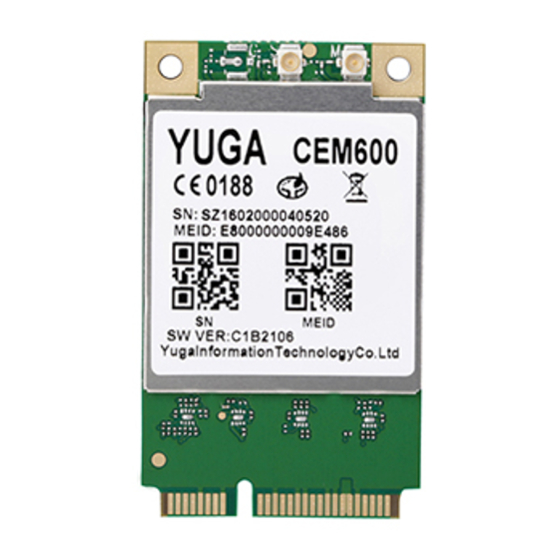
CEM600 EVDO Mini PCIE Module Hardware User Guide Chapter 2. Module review 2.1 Product Introduction CEM600 is a PCI Express Mini Card 1.2 standard interface CDMA2000 1X EVDO Rev.A module, using Qualcomm's latest EVDO single-chip platform QSC6085, supporting embedded operating systems such as WinCE/Linux, with voice, SMS and high-speed data services. -
Page 7: Main Function Of The Module
CEM600 EVDO Mini PCIE Module Hardware User Guide 2.3 Main function of the module The main functions of the CEM600 module are as follows: Support CDMA800/1900 frequency band Support GPS function Support for primary/diversity antenna reception Support 1 USB 2.0 Fullspeed interface ... -
Page 8: Chapter 3. Technical Specifications
CEM600 EVDO Mini PCIE Module Hardware User Guide Chapter 3. Technical specifications 3.1 Overall technical indicators The overall technical specifications of the CEM600 module are shown in the following table: Table 3-1 Overall technical indicators Characteristic Description IS95A/B CDMA2000 1x Rev.0 CDMA standard CDMA2000 1xEV-DO Rev. -
Page 9: Rf Emission Indicators
CEM600 EVDO Mini PCIE Module Hardware User Guide <-47dBm/30KHz(Other frequencies) FER≤3.0%(Test 1: Rate Set 1(9600bps) FER≤1.0%(Test 2: Rate Set 1(9600bps) FER≤0.5%(Test 3: Rate Set 1(9600bps) FER≤1.0%(Test 4: Rate Set 1(4800bps) FER≤1.0%(Test 5: Rate Set 1(2400bps) Demodulation of forward traffic FER≤1.0%(Test 6: Rate Set 1(1200bps)... -
Page 10: Power Supply Dc Characteristics
CEM600 EVDO Mini PCIE Module Hardware User Guide 3.4 Power Supply DC Characteristics The DC characteristics of the CEM600 module power supply are shown in the following table: Table 3-4 DC characteristics of the power supply Parameter Description Typical Unit Module input power 3.3... -
Page 11: Chapter 4 Interface Definition
CEM600 EVDO Mini PCIE Module Hardware User Guide Chapter 4 Interface definition The CEM600 module interface definition is shown in the following table: Table 4-1 Interface definition Standard Pin definition Description Pin definition properties Analog audio input positive WAKE# MIC_P... - Page 12 CEM600 EVDO Mini PCIE Module Hardware User Guide 1.5V Unused Ground General purpose input and output SMB_CLK GPIO1 Two way signal 1 (optional function) PETn0 UART1_DTR_N Input DTE is ready General purpose input and output SMB_DATA GPIO3 Two way signal 3 (optional function)
-
Page 13: Chapter 5. Main Function Interface Description
CEM600 EVDO Mini PCIE Module Hardware User Guide Chapter 5. Main function interface description 5.1 UART interface (optional function) Table 5-1 UART Interface Definition Signal name I/O properties High value Description UART1_RXD Input 2.6V UART1 data reception UART1_TXD Output 2.6V... -
Page 14: Usb Interface
CEM600 EVDO Mini PCIE Module Hardware User Guide Figure 5-2 Serial connection reference design 5.2 USB interface Table 5-2 USB Interface Definition Signal name I/O properties High value Description USB_D- Two way 3.3V USB data cable - USB_D+ Two way 3.3V... -
Page 15: Pcm Interface (Optional Feature)
CEM600 EVDO Mini PCIE Module Hardware User Guide Figure 5-4 USB interface reference design Note: 1. As shown in the USB interface reference design drawing, it should be noted that the ESD protection device should be added to the data line. The USB trace design of the DTE interface board needs to strictly follow the USB2.0 protocol requirements, and the differential... -
Page 16: Audio Interface
CEM600 EVDO Mini PCIE Module Hardware User Guide Figure 5-5 PCM digital voice application reference design 5.4 AUDIO interface Table 5-4 AUDIO Interface Definition Signal name I/O properties High value Description MIC_P Analog input 1.8V Audio input positive end MIC_N Analog input 1.8V... -
Page 17: Ruim Card Interface
CEM600 EVDO Mini PCIE Module Hardware User Guide Figure 5-6 Differential Audio Interface Reference Design The differential audio channel can also work in single-ended mode, such as an external headphone jack. The single-ended audio interface is preferably packaged on the outside of the PCB design. -
Page 18: Control And General Purpose I/O Interface (Optional Feature)
CEM600 EVDO Mini PCIE Module Hardware User Guide It is recommended to connect 33 μ capacitors in parallel between RUIM_CLK, RUIM_DATA, RUIM_RESET and GND to filter out the interference of RF signals, and connect 33 ohm resistors in series on RUIM_CLK, RUIM_DATA, RUIM_RESET. Also, be careful to place the ESD protection device next to the RUIM deck. -
Page 19: Power Interface
CEM600 EVDO Mini PCIE Module Hardware User Guide output signal 1(default is input, internal pull-up) Work status light, "low" is LED_WWAN_N Current input 3.3V valid, default is "high" LED_RES1_N Current input 3.3V Alternate LED light control LED_RES2_N Current input 3.3V... -
Page 20: Antenna Socket Interface
CEM600 EVDO Mini PCIE Module Hardware User Guide VCC_3V3 power input 3.3V 3.3V main power supply VCC_3V3 power input 3.3V 3.3V main power supply Ground The CEM600 module receives a 3.3V power supply from external sources (±9% accuracy). The maximum average power consumption of the module is about 700mA. It is recommended to use an LDO or switching power supply of 1.5A or higher. - Page 21 CEM600 EVDO Mini PCIE Module Hardware User Guide Figure 5-10 Antenna interface ESD protection recommended Shang Hai YUGE Information Technology co., LTD Page 20 of 25...
-
Page 22: Chapter 6. Structure
CEM600 EVDO Mini PCIE Module Hardware User Guide Chapter 6. structure 6.1 Structural size Figure 6-1 Outline drawing of the CEM600 module Shang Hai YUGE Information Technology co., LTD Page 21 of 25... -
Page 23: Mini Pci Express Connector
CEM600 EVDO Mini PCIE Module Hardware User Guide The structural dimensions of the CEM600 module are as follows: Figure 6-2 CEM600 module structure size Specific size: 51mm (length)×30mm (width)×2.6mm (height) 6.2 Mini PCI Express connector The CEM600 module interface complies with the PCI Express Mini Card 1.2 interface standard, and PCI Express Mini Card connectors conforming to this standard can be used with it, such as Molex's 679100002. -
Page 24: Rf Connector
CEM600 EVDO Mini PCIE Module Hardware User Guide Figure 6-3 PCI Express Mini Card Connector 6.3 RF connector The RF connector used on the CEM600 module is U.FL-R-SMT-1 (10) from HRS. Figure 6-4 Antenna connector size The RF connector plug for this connector is the U.FL-LP series from HRS. - Page 25 CEM600 EVDO Mini PCIE Module Hardware User Guide Figure 6-5 Antenna connector mating plug Shang Hai YUGE Information Technology co., LTD Page 24 of 25...
Need help?
Do you have a question about the CEM600 EVDO Mini and is the answer not in the manual?
Questions and answers