Table of Contents
Advertisement
Quick Links
Advertisement
Table of Contents

Subscribe to Our Youtube Channel
Summary of Contents for Trimteck Optimux HPP5500 Series
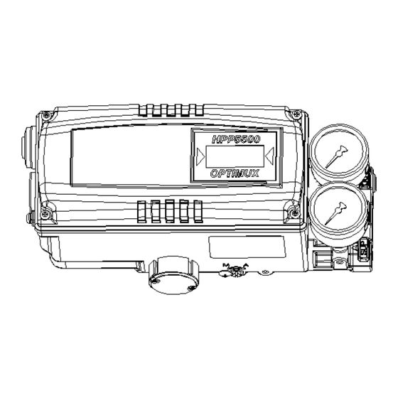
- Page 1 SMART POSITIONER PRODUCT MANUAL HPP5500 SERIES VERSION 1.00...
-
Page 2: Table Of Contents
Contents 1. Introduction …………………………………………………………………………………………… 1.1 General information for the users ………………………………………………………………. 1.2 Manufacturer Warranty …………………………………………………………………………… 2. Product Description ………………………………………………………………………………….. 2.1 General …………………………………………………………………………………………….. 2.2 Main Features and Functions ……………………………………………………………………. 5 2.3 Label Description ………………………………………………………………………………….. 5 2.4 Product Number …………………………………………………………………………………… 6 2.5 Product Specification ……………………………………………………………………………… 7 2.6 Parts and Assembly ……………………………………………………………………………….. - Page 3 6. Operation ………………………………………………………………………………………………… 20 6.1 Safety ………………………………………………………………………………………………. 20 6.2 Button Description ………………………………………………………………………………… 20 6.3 Run Mode (RUN) ………………………………………………………………………………….. 20 6.3.1 Auto Calibration (AUTO CAL) …………………………………………………………. 21 6.3.1.1 AUTO1 Calibration (AUTO1) ……………………………………………….. 21 6.3.1.2 AUTO2 Calibration (AUTO2) ……………………………………………….. 21 6.3.1.3 AUTO3 Calibration (AUTO3) ……………………………………………….. 22 6.3.2 Manual Mode (MANUAL) ………………………………………………………………...
-
Page 4: Introduction
1. Introduction General Information for the users Thank you for purchasing TRIMTECK products. Each product has been fully inspected after its production to offer you the highest quality and reliable performance. Please read the product manual carefully prior to installing and commission the product. -
Page 5: Product Description
2. Product Description General HPP5500 series Smart Valve Positioner accurately controls valve stroke in response to an input signal of 4-20mA from the controller. Built-in micro-processor optimizes the positioner’s performance and provides unique functions such as Auto-Calibration, PID Control, Alarms, and HART Protocol Communications. Main Features and Functions ... -
Page 6: Product Number
Product Number ** HPP5500 series can be used for direct-mounting application. HPP5500 series... -
Page 7: Product Specification
Aluminum Diecasting Material 2.0kg Weight Epoxy Polyestere Powder Coating Painting Tested under ambient temperature of 20’C, absolute pressure of 760mmHg, and humidity of 65%. Please contact TRIMTECK for detailed testing specification. * Explosion proof certification is in progress. HPP5500 series... -
Page 8: Parts And Assembly
Parts and Assembly Fig. 2. HPP5500L series exploded view Fig. 3. HPP5500R+LS series exploded view HPP5500 series... -
Page 9: Product Dimension
Product Dimension 2.7.1 HPP5500L 2.7.2 HPP5500R 2.7.2.1 HPP5500R standard HPP5500 series... -
Page 10: Installation
2.7.2.2 HPP5500R with L/S option 3. Installation Safety When installing a positioner, please ensure to read and follow safety instructions. Any input or supply pressures to valve, actuator, and / or to other related devices must be turned off. ... -
Page 11: Installation Steps
Please refer to the backside of the positioner for size of the bolts. The standard bolt size is M8 x 1.25P. Please contact TRIMTECK for other bolt sizes. 3. Attach the positioner with bracket to the actuator yoke –... - Page 12 7. Check if feedback lever is parallel to the ground at 50% of the valve stroke. If it is not parallel, adjust the bracket or feedback link bar to make parallel. Improper installation may cause poor linearity and may create unnecessary hunting during the operation. 8.
-
Page 13: Hpp5500L Direct-Mounting Installation
HPP5500L Direct-Mounting Installation HPP5500L can be installed on direct-mounting / tube-less type actuator. 3.3.1 Installation Steps 1. Please remove the plug which blocks OUT port on the back of the HPP5500 unit. OUT ports on the side of the positioner should be blocked by plugs. Remove Block 2. -
Page 14: Hpp5500R Installation
HPP5500R Installation HPP5500R should be installed on rotary motion valve such as ball or butterfly type which uses rack and pinion, scotch yoke or other type of actuators which stem rotates 90 degrees. Before proceeding with the installation, ensure following components are available. ... -
Page 15: Connections
Supply pressure should be clean and dry air – avoiding moisture, oil or dust. Always recommended to use air filter regulator (i.e. YT-200 series). TRIMTECK has not tested positioner’s operation with any other gases other than clean air. Please contact TRIMTECK for any questions. Supply Pressure Condition ... -
Page 16: Double Acting Actuator
4.4.2 Double acting actuator Double acting type positioner is set to use OUT1 and OUT2 port. As input signal increases, the supply pressure will be supplied through OUT1 port. Fig. 8: Double acting linear (left) and rotary (right) type actuator Connection –... -
Page 17: Terminal Overview
4.5.2 Terminal Overview Fig. 9: Positioner Terminal IN +: Input Signal (+) IN -: Input Signal (-) Ground OUT+: Feedback Signal (+) OUT-: Feedback Signal (-) 4.5.2.1 Limit Switch Terminal – Mechanical Type HPP5500 series... -
Page 18: Limit Switch Terminal-Proximity Type
4.5.2.2 Limit Switch Terminal – Proximity Type 4.5.2.3 Ground 1. Ground must be done before operating the positioner. 2. Open terminal cover and locate ground terminal plate on the right hand bottom side of the terminal plate. The outer cable entry is located at outside of the terminal. Please make sure that the resistance is less than 100ohm. -
Page 19: Auto/Manual Switch (A/M Switch)
Auto/Manual Switch (A/M Switch) Auto/Manual Switch allows the positioner to be functioned as by-pass. If switch is set as Auto, the positioner will operate per input signal. If switch is set as Manual, the positioner will send supply pressure directly to the actuator. Option PCB adjustment 5.3.1 By adding option sub-pcb, the positioner can have options. -
Page 20: Operation
** Option Jumper must be removed, when HART option included sub-PCB is being mounted. 6. Operation Safety Following process will operate valve and actuator. Before proceed with any AUTO Calibration, please separate valve from the entire system, so AUTO Calibration will affect entire valve process. -
Page 21: Auto Calibration (Auto Cal)
opposite order. By pressing <ESC>, the display will return to “RUN” mode. 6.3.1 Auto Calibration (AUTO CAL) Auto Calibration (AUTO CAL) automatically calibrates the positioner. “AUTO CAL” process takes about 2~3 minutes, and the duration of the process varies upon the size of the actuator. There are 3 types of AUTO CAL. -
Page 22: Auto3 Calibration (Auto3)
⇨ <ENTER> 6.3.1.3 AUTO3 Calibration (AUTO3) AUTO3 changes only the valve parameters. ⇨ ⇨ ⇨ <ENTER> <ENTER> <DOWN> 6 seconds 2 times ⇨ <ENTER> 6.3.2 Manual Mode (MANUAL) Manual mode is used to maneuver valve stem manually. During “MANUAL”, the positioner bypasses supply air to the actuator. -
Page 23: P Value (Kp)
⇨ ⇨ ⇨ <ENTER> <DOWN> <ENTER> 6 seconds 2 times ⇨ ⇨ ⇨ <ENTER> <ESC> <UP>/<DOWN> 3 times <ENTER> 6.3.3.2 P value (KP) P value indicates the ratio of the compensation signal based on the percentage of error allowance. As the value increase, the positioner finds the target value quickly, but it is more likely to have hunting. -
Page 24: I Value (Ki)
6.3.3.4 I value (KI) I value indicates the additional compensation signal based on the percentage of error allowance. As the value increase, it is more likely to have hunting. As the value decreases, the positioner will move slowly to the target position. ⇨... -
Page 25: Zero-Point (Tr_Zero) And End-Point (Tr_End) For Transmitter
6.3.4.2 Zero-Point (TR_ZERO) and End-Point (TR_END) for Transmitter TR_ZERO adjusts the zero point of the transmitter (4-20mA feedback), and TR_END adjusts the end point of the transmitter (4-20mA feedback) ⇨ ⇨ ⇨ <DOWN> <ENTER> <UP>/<DOWN) Match feedback <ENTER> Zero Adjustment signal with 4mA ⇨... -
Page 26: Normal / Reverse Hart Signal (Ht_Norm / Revs)
⇨ ⇨ ⇨ <DOWN> <ENTER> <ESC> 3 times 6.3.4.5 Normal / Reverse HART Signal (HT_NORM / REVS) HART signal from the positioner can be viewed as normal or as reverse. ⇨ ⇨ ⇨ <ENTER> <DOWN> <ENTER> 6 times Zero Adjustment ⇨... -
Page 27: Characteristic Adjustment (Char)
6.3.5.2 Characteristic Adjustment (CHAR) The valve characteristic can be set on the field’s requirement. There are 3 types of characteristics – linear (LIN), equal percentage (EQ), and quick open (QO). ⇨ ⇨ ⇨ <ENTER> <DOWN> <ENTER> ⇨ ⇨ <ESC> <UP>/<DOWN> 3 times <ENTER>... -
Page 28: Tight Shut Close (Tshut Cl)
⇨ ⇨ <ESC> <UP>/<DOWN> 3 times <ENTER> 6.3.5.5 Tight Shut Close (TSHUT CL) Tight Shut Close allows the valve to close completely as the input signal reaches around 4mA. ⇨ ⇨ ⇨ <ENTER> <DOWN> <ENTER> 6 seconds 4 times ⇨ ⇨... -
Page 29: Custom End Setting Mode (Cst End)
6.3.5.8 Custom End Setting Mode (CST ENd) Custom End Setting Mode allows the user to set any specific point as end position. For example, the end point can be set at input signal of 11mA. The difference between zero and end point must be greater or equal to 4mA. ⇨... -
Page 30: Error And Warning Code
BIAS value when valve position is at 25% bIAS 25 BIAS value when valve position is at 75% bIAS 75 Total used time duration. If a unit was used less than 1 minute, the 0Y 0d time will not accumulate. Time elapsed for valve to fully open FULL_OP Time elapsed for valve to fully close. -
Page 31: Warning Code
I-value reaches at maximum or minimum limit. Perform auto calibration. Changes in valve friction. Check setting pressure of actuator. Changes in setting pressure of actuator. Warning code Warning Description Action Code Re-install the positioner. Ensure the feedback lever does not ... -
Page 32: Main Software Map
8. Main Software Map HPP5500 series... - Page 33 TRIMTECK Address : 12461, NW 44 Street, Coral Springs, FL33065 USA Phone : 954-753-5545 Fax : 954-753-5561 Web: www.trimteck.com Issued : 2016. January Version 1.00 HPP5500 series...
Need help?
Do you have a question about the Optimux HPP5500 Series and is the answer not in the manual?
Questions and answers