Advertisement
Hoffman
Installation & Operating
Instructions
Thermostat & Hardware
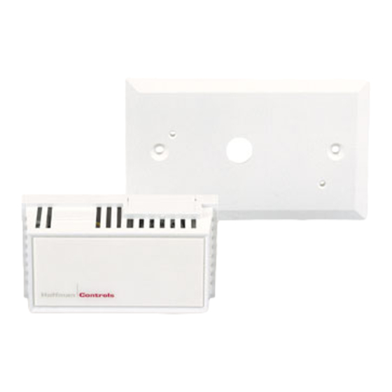
• Thermostat (Cover & Base), white
• Electrical Box Cover (Size 2" X 4" electrical box)
Mounting Hardware
• Two #6 x 1/2" painted screws (for the wall plate to
J Box).
• Two #6 x 1" flathead phillip screws (for the thermostat
wall plate).
• Three wire nuts.
• Wall anchors when wall plate is not required.
Electrical Box Mounting
Figure 1
1. Remove thermostat cover from thermostat base. (See
Figure 3.)
2. Insert wires from thermostat base through electrical box
cover (1/2" hole).
3. Wire thermostat to field thermostat cable, using wire
nuts. (Color-code to assure proper connection.)
4. Mount electrical box cover to horizontally mounted
electrical J Box with two #6 x 1/2" painted head
screws. (See Figure 1.)
5. Attach thermostat base to wall plate. Do Not Remove
nylon shims holding two premounted #6 x 1" flathead
philip screws. Thermostat base will mount with less
than 1/16" clearance to wall plate. Clearance is required
to allow cover to snap over sub-base.
CAUTION
Sub-base should be firmly secured to plate. Do
not over tighten!
6. Check thermostat base to see if it is centered evenly on
wall plate. If incorrectly installed, the thermostat base
will not frame on center of electrical box cover;
Review #4.
Page 1 of 2
|
Controls
7. Place thermostat cover over thermostat base, securing
left side first; push right side until "snap" secures
(locks) cover in place.
Direct Wall Surface Mount
Figure 2
(Sub-Base directly to the wall)
1. Remove thermostat cover from thermostat base. (See
Figure 3).
2. Wire thermostat base to field thermostat cable, using
wire nuts. (Color code to assure proper connection.)
3. Position base on the wall at proposed mounting loca-
tion (using premounted #6 x 1" flathead screws installed
in sub-base as template), mark wall surface for anchor
mounting hole location.
4. Punch or drill holes at markings for plastic wall
anchors. Do Not Remove nylon shims holding screws in
base before mounting to wall. Install wall anchors and
attach base to wall with two #6 x 1" phillip screws.
Thermostat base will mount with less than 1/16"
clearance to wall.
5. Place thermostat cover over base, securing left side first,
push right side until "snap" secures cover in place.
Cover Release Instructions
Figure 3
1. When facing the thermostat cover, place a small screw-
driver between the 4th and 5th ribbed openings on the
right side of the thermostat cover. The thermostat
assembly should be held against a solid surface if it is
not mounted on the wall.
2. Push firmly to the left and to the back side of cover
until latch releases the base from the cover.
3. To replace cover, place over base, left side first, press
firmly until the cover "snaps" to secure (lock) in place.
207-W Series Electronic Thermostat Installation & Operating Instructions
207-W Series
Electronic Thermostat
Advertisement
Table of Contents

Summary of Contents for Hoffman Controls 207-W Series
- Page 1 3. To replace cover, place over base, left side first, press will not frame on center of electrical box cover; Review #4. firmly until the cover “snaps” to secure (lock) in place. Page 1 of 2 207-W Series Electronic Thermostat Installation & Operating Instructions...
- Page 2 Figure 2 Diagrams Shows major items of assembly used when mounting the thermostat directly to the wall. Do Not Remove nylon Figures 1 & 2 describe major items of electronic thermostat shims (not shown) from #6 x 1 phillip screws. assembly when mounted to electrical box and directly to wall.
Need help?
Do you have a question about the 207-W Series and is the answer not in the manual?
Questions and answers