Table of Contents
Advertisement
Quick Links
DIY599.com
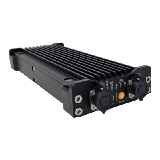
RF linear power amplifier with build-in antenna tuner (ATU)
PA500
INSTRUCTION MANUAL
Version 2
operating frequency range between 3.5MHz-30MHz
The device requires an amateur radio transceiver to operate.
This device is for use by licensed radio amateurs only
FCC-ID: 2A2IEPA500
© 2021 DL4KA
1
Advertisement
Table of Contents

Related Manuals for DL4KA PA500

Summary of Contents for DL4KA PA500
- Page 1 RF linear power amplifier with build-in antenna tuner (ATU) PA500 INSTRUCTION MANUAL Version 2 operating frequency range between 3.5MHz-30MHz The device requires an amateur radio transceiver to operate. This device is for use by licensed radio amateurs only FCC-ID: 2A2IEPA500 © 2021 DL4KA...
-
Page 2: Table Of Contents
connectors ............................... 3 getting started ............................4 powering up ............................4 LEDs and Button functions ........................5 device configuration ..........................6 good to know about BYPASS Mode ....................... 6 good to know about automatic Mode ....................6 manual band selection ........................... 7 compatible transceivers ......................... -
Page 3: Connectors
connectors left side there is no reverse polarity protection, incorrect wiring will destroy the device. right side... -
Page 4: Getting Started
The PA500 need to be connected to a transceiver. In the simplest case, a connection of the PTT signal from the transceiver is sufficient to control the PA. In this specific case, the frequency band to be used need to be set manually in PA-Mode (no bypass) on the PA500 (TAP the BAND Button). -
Page 5: Leds And Button Functions
LEDs and Button functions left side The correct Band must be selected, otherwise the PA will not transmit right side... -
Page 6: Device Configuration
device configuration good to know about BYPASS Mode if the PA is operated in the interface Mode 0 (simple PTT controlled) AND the PA is in the BYPASS Mode, Band-Filters are off, no LED indication for Filter status. if the PA is operated in the interface Mode 1-7 AND the PA is in the BYPASS Mode, Band-Filter LED shows the status of the selected Filter-Bank, but Band-Filters will switch off when the PTT is pressed. -
Page 7: Manual Band Selection
The PA500 has 4 Band selector settings 80m, 40m, 20m and 10m. Most of other Frequencies between these Bands can also be used. The table describes the selection that must be made for a specific Band to use. -
Page 8: Operating Modes And Drive Power
operating modes and drive power operating max. drive power peak drive max. PEP transmit duty cycle mode power PEP RF power @ max. RF power **** ***** periodic SSB 3W@12V/2W@16V max. 3min. continues carrier duty cycle 50/50 for 6min. 3W@12V/2W@16V max. -
Page 9: Safety Operating Area Soa
safety operating area SOA RF output power vs. RF input power RF output power in Watt @ 16V Output power limitation Switch to bypass @ 60W PEP safe operation area RF output power vs. operating voltage input RF output power in Watt @5W RF Input Output power limitation Switch to bypass @ 60W PEP safe operation area... -
Page 10: Special Transceiver Characteristics (In Manual Modes)
Known characteristics in connection with the operation of the PA500 are listed here. Yaesu FT817/818 If the Yaesu FT817/818 is used with a CAT interface cable, the transceiver will not turn on if the PA500 has already been turned on. Therefore, make sure that the transceiver is always switched on first and then the PA500. - Page 11 ELECRAFT KX3 LAB599 TX-500...
-
Page 12: Safety Instructions
safety instructions The device can get very hot. It must be operated in such a way that there are no heat-sensitive objects near the device. Please ensure that the device is always well-ventilated during operation. Please be aware that the device is still hot for a while after use. Please keep the device away from children, the device develops a temperature level which can cause burns to the skin. -
Page 13: Power Considerations On The Go
The "Buddipole POWERmini USB" is a pocket-sized 12 VDC portable DC power management system with built in solar controller that is particularly suitable for portable operations. This device can deliver up to 32A at 12V. this makes it a suitable device for supplying your transceiver and the PA500 with power on the go. -
Page 14: General Troubleshooting
Check your Transceiver and connection When the PA500 current draw is too high (more than 15A), or a short circuit occurs, the internal fuse may blow. The unit will then no longer turn on. The device needs a service. Do not allow the maximum output power of the amplifier to exceed 40 W. -
Page 15: Device Label And Id Location
Device LABEL and ID location WARRANTY LIMITATIONS Any of the following will void the warranty applicable to the product and its accessories: A. Modification-, removal-, or maintenance of the internal circuitry, without permission and authorization; B. Unauthorized change of product’s embedded software; C. -
Page 16: Note Amateur Radio Operation
PA500. Further, this Manual is provided “as is” and DIY599 shall not be liable for possible errors contained herein.
Need help?
Do you have a question about the PA500 and is the answer not in the manual?
Questions and answers