Advertisement
lnstallation Manual
Contents:
- Generai lnformation
- 4-wire / 6-wire load cells
- Electrical connections
- 4-wire load cells trimming
- Internal Jumpers
5ENECA s.r.l.
Via Austria, 26- 35127 - PADOVA- ITALY
r
el. +39.049.8705355 - 8705359 - Fax +39.049.8706287
e-mail: info(@seneca.it -
This document is property of SENECA srl. Duplication and reprodution are
forbidden, if not authorized. Contents of the present documentation refers to
products and technologies described in the document may be modified without
prior notice Content of this documentation is subject to periodical revision.
CSSEI
N ECA
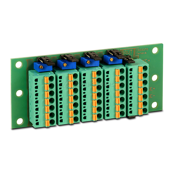
SG-EQ4
4 LOAD CELLS
JUNCTION BOX
www.seneca.it
MI00155-3-EN
ENGLISH - 1/7
Advertisement
Table of Contents

Summary of Contents for Seneca SG-EQ4
- Page 1 +39.049.8705355 - 8705359 - Fax +39.049.8706287 e-mail: info(@seneca.it - www.seneca.it This document is property of SENECA srl. Duplication and reprodution are forbidden, if not authorized. Contents of the present documentation refers to products and technologies described in the document may be modified without prior notice Content of this documentation is subject to periodical revision.
- Page 2 GENERAL INFORMATION Most industriai load cells are used in multiple load cell weighing systems. Load cells should be electrically connected in such a way that the signal (output) lines, excitation (power supply) and sense (when present) lines are in parallel. Usually the connection is not made at the signal conditioning device, but in a separate housing, a so called junction box, located adjacent to the weighing system.
- Page 3 AII Load cells should be placed on the same horizontal level. Check for mechanical unequal load conditions before trimming the load cells .. 4-Wire Load Cells Connections 'l!!!!"! - !!!!!""l!!l"'m!!!!!!!!!!--· --l!l!!!!!--- 1!!!!"!! "1'!!!!!!1!!1"!! · r------- · · --+- " ----...i:...·..::::���1- ■('\, ·...
- Page 4 Grounding and Shielding Proper grounding and shielding can be criticai to the successful application of load cells which are generating low level signals (< 5 µV/ scale division). The basic rule is: A void continuous ground loops; a system should not be grounded at multiple points. This may occur, tor example, if the shield of the load ce/I cab/e is connected to earth at both ends.
- Page 5 4-WIRE LOAD CELLS TRIMMING The figure below shows a diagram of three excitation trimmed load cells. A temperature-independent variable resistor or potentio-meter of typically 20 inserted in the + excitation lead of each load cell.. __ ...,..,..____ ..______ ..,.._ Exc tal D ""-!I!-------+--------•...
- Page 6 Output Step 3 Step 4 Step 5 (mVN) 2.995 2.995 10.05 Do not adjust 3.001 30.1 O 3.001 10.030 3.003 30.10 3.003 10.023 2.998 30.10 2.998 10.040 Warning: The reduction of sensitivity of one load cell will cause a change in zero of all load cells.
- Page 7 4-wire Load Cells JUMPERS POSITION SETTING Trimmer On J1 / J2 / J3 / J4 in position 1 Trimmer OFF J1 / J2 / J3 / J4 in position 3 JA / JB in position 1 6-wire Output 4-wire Output JA / JB in position 3 6-wire Load Cells JUMPERS POSITION...
Need help?
Do you have a question about the SG-EQ4 and is the answer not in the manual?
Questions and answers