Advertisement
Quick Links
Advertisement

Related Manuals for NIPROS HDM-70WV

Summary of Contents for NIPROS HDM-70WV
- Page 1 HDM-70WV HD Monitor HDモニター HDM-70WV/S O perating I nstruc tion s Before operating the system, please read this manual thoroughly and remain it for future reference. 取 扱 説 明 書 ご使用の前に必ずこの取扱説明書をお読みください。 なお、 取扱説明書は必要に応じてご覧になれるよう 大切に保管してください。 Volume1, 1st edition Ver.1.0...
- Page 2 WARNING For the customers in the U.S.A. To reduce the risk of fire or electric shock,do not expose this apparatus to rain This equipment has been tested and found or moisture. to comply with the limits for a Class A digital device, pursuant to Part 15 of the To avoid electrical shock, do not open the FCC Rules.
-
Page 3: Table Of Contents
Contents 目次 HD Monitor HDM-70WV HDM-70WV 目次 Names and Functions of Parts 各部名称と働き Front panel フロントパネル Rear panel リアパネル Left side, Right side,Upper and Bottom 左側面,右側面,上面,下面, Fixing 組み立て方法 Connection 接続方法 Adjustments and Settings 調整・設定 Accessories 付属品 Outside View and Dimensions 外形寸法図 Specifications 仕様... -
Page 4: Names And Functions Of Parts 4 各部名称と働き
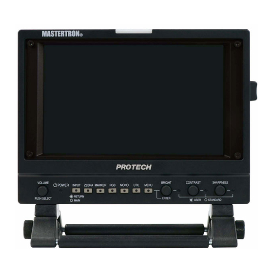
Names and Functions of Parts 各部名称と働き HD Monitor HDM-70WV HDM-70WV 各部名称と働き Front panel フロントパネル Screen (with Bezel and Protector) The display screen is 7.0 inches LCD with the bezel( open size : 152.4mm 91.4mm) . And the screen is covered with the protector(181.4mm 100.6mm). スクリーンは 7インチ液晶で、 画面寸法は 152.4mm 92.4mm です。 プロテクターで保護されています。 Front TALLY Indicator LED (RED and GREEN) Lights up to RED or GREEN when the tally signal is input to the TALLY IN 1 connector. Or lights up when the only RED tally signal is input to the TALLY IN 2. GREEN : Lights up when the signal to the TALLY IN 1 connector is 2 - 4V. RED : Lights up when the signal to the TALLY IN 1 connector is 4 - 5V. or when the signal to the TALLY IN 2 connector is shortened. フロントタリーは、 TALLY IN 1 のタリー信号で RED/GREEN に点灯します。 または、 TALLY IN 2 のタリー信号では RED のみ点灯します。 GREEN : TALLY IN 1 コネクタの場合、 タリー信号の電圧が 2 - 4V のとき RED : TALLY IN 1 コネクタの場合、 タリー信号の電圧が 4 - 5V のとき TALLY IN 2 コネクタの場合は、 レッ ドのみ。 タリー信号入力は、 接点の short/open です。 TC TALLY: The front TALLY indicator can be used as the TC TALLY indicator by the MENU setting. (See page TC TALLY(red only) lights up when the HD-SDI signal with the embedded TC signal is input to the SDI(HD/SD) IN or RET IN connector. TC TALLY: レッ ドタリーは、 メニューで TC TALLY に設定できます。... - Page 5 HD Monitor HDM-70WV Names and Functions of Parts Front panel フロントパネル POWER Indicator Lights up when the POWER switch is turned on and the power is supplied to the DC IN connector. POWER スイ ッチが ON のとき点灯します。 VOLUME / PUSH SELECT switch By rotating the knob adjust the audio volume level of the monitor speaker (when the headphone is disconnected) or the headphone level connected to the jack( ). By pressing this switch select the audio channel, CH 1&2→3&4→1→2→3→4→5→6→7→8→ in sequence, to monitor by the monitor speaker or the headphone. ツマミを回して、 背面のモニタースピーカーまたはヘッドホンでモニターする音量を調整します。 このツマミ(ボタン)を順次押すと、 モニターする信号(モニタースピーカーまたはヘッ ドホンへ出力される信号)が切り替えられます。 ( CH 1&2→3&4→1→2→3→4→5→6→7→8→ の順に切り替わります。 ) INPUT select switch Selects a input signal by pressing in sequence. The LED indicator on the INPUT switch lights up, when the (SDI) RET IN signal is selected by operating the zoom remote controller. Indication Input signal (input connector) on the screen [SDI-MAIN] SDI signal input to the SDI(HD/SD) IN 1 connector [SDI-RETURN] SDI signal input to the RET IN connector [COMPONENT] analog (HD) component signals input to the ANALOG Y/P connectors [CAMERA] VF signals input to the I/F connector(D-sub 15-pin) from the camcorder. (analog (HD) component signals) INPUT 切替スイ ッチを押して、 入力映像信号を順に切り替えます。 SDI(HD/SD) IN 1 [SDI-MAIN] → RET IN [SDI-RETURN]...
- Page 6 HD Monitor HDM-70WV Names and Functions of Parts Front panel フロントパネル RGB switch Selects the image → Blue only (Blue only, GREEN only, RED only, full color) in sequence. ↓ GREEN only ↓ RED only ブルーオンリー→グリーンオンリー→レッドオンリー→フルカラー→の順に切り替えます。 ↓ full color( LED off ) ↓ MONO switch Selects the image, monochrome( LED on ) or color. 画面表示のカラー, モノクロ の切替えをします。 UTIL select switch Selects the utility function in sequence as follows. ユーティリティー(測定器機能)を順次切り替えます。 → WAVEFORM ウェーブフォーム → ↓ WAVEFORM+VECTORSCOPE ウェーブフォーム+ベクトルスコープ → ↓ WAVEFORM+AUDIO 8CH ウェーブフォーム+オーディオ 8CH → ↓ ウェーブフォーム+ベクトルスコープ+オーディオ 8CH → WAVEFORM+VECTORSCOPE+AUDIO 8CH ↓ ウェーブフォーム(全画面) → WAVEFORM(full screen) ↓ ベクトルスコープ (全画面)→ VECTORSCOPE(full screen) ↓...
- Page 7 HD Monitor HDM-70WV Names and Functions of Parts Front panel フロントパネル (2) Rotating knob adjusts(confirms) a value. SHARPNESS (1) Pressing knob selects USER setting and LED lights on. BRIGHT level control volume and select switch / LED Indicator Pressing the knob selects the USER setting or STANDARD(default) setting. When USER setting is selected( LED indicator lights on ), rotating this knob adjusts the brightness. When the STANDARD setting is selected(LED lights off), the brightness is set to the factory setting(50). このツマミを押すとユーザー設定と標準設定(デフォルト)とが切替えできます。 ユーザー設定のときLED 表示が点灯します。 BRIGHT(明るさ) は、 ツマミを回して調節します。 STANDARD(デフォルト標準値)は、 BRIGHT = 50 に設定されています。 CONTRAST control volume and select switch / LED Indicator Pressing the knob selects the USER setting or STANDARD(default) setting. When USER setting is selected( LED indicator lights on ) rotating this knob adjusts the contrast. When the STANDARD setting is selected(LED lights off), the contrast is set to the factory setting(80). このツマミを押すとユーザー設定と標準設定(デフォルト)とが切替えできます。 ユーザー設定のときLED 表示が点灯します。 コントラスト は、 ツマミを回して調節します。 STANDARD(デフォルト標準値)は、 コントラスト = 80 に設定されています。 SHARPNESS control volume and select switch / LED Indicator Pressing the knob selects the USER setting or STANDARD(default) setting. When USER setting is selected( LED indicator lights on ) rotating this knob adjusts the sharpness. When the STANDARD setting is selected(LED lights off), the sharpness is set to the factory setting(50). このツマミを押すとユーザー設定と標準設定(デフォルト)とが切替えできます。 ユーザー設定のときLED 表示が点灯します。 シャープネス は、 ツマミを回して調節します。 STANDARD(デフォルト標準値)は、 シャープネス = 50 に設定されています。...
- Page 8 HD Monitor HDM-70WV Names and Functions of Parts Operating the Menus メニューの操作 Menu Display メニューの表示 Menu list Press the MENU button. INPUT SDI-MAIN INFO [1080 i/60] The menu list is displayed on the screen. VIDEO FORMAT 1080 i/60 PICTURE VERSION ### MARKER AUDIO [ON] WAVEFORM [ON] VECTORSCOPE [ON] ZEBRA [OFF] SETUP Menu Setting メニューの設定 Menu Selection and fixing By rotating the ENTER knob button move the cursor to the desired item Menu list Submenu list position and then the submenu list is displayed. RETURN INFO [1080 i/60] Press the knob to fix the selected WAVEFORM [ON]...
- Page 9 HD Monitor HDM-70WV Names and Functions of Parts MENU list メニュー項目 <MENU> メニュー <Submenu & [factory setting] > 設定項目 <Setting> 設定値 INPUT SDI-MAIN INFO [1080 i/60] VIDEO FORMAT 1080i/60 VERSION ### RETURN PICTURE SATURATION [50] 0/- - -/50/- - -/100 ピクチャー SHARPNESS [0] 0/- - -/50/- - -/100 COLOR MATRIX [YPBPR] COLOR YPBPR RED BIAS [0] カラー -128/ - - - - - /127 GREEN BIAS [0] -128/ - - - - - /127 BLUE BIAS [0] -128/ - - - - - /127 RED GAIN [ 1.00]...
-
Page 10: Rear Panel
HD Monitor HDM-70WV Names and Functions of Parts Rear panel リアパネル I/F connector ( HD D-sub 15-pin, female ) 1 R-Y IN 2 Y IN HD D-sub 15-pin Connector 3 B-Y IN Used for connecting the HDM-70WV Pin Assignment 4 REC TALLY instead of the VF to the VF connector 5 SHIELD of the camera. 6 AGND R-Y Connect the HD D-sub 15-pin cable 7 AGND Y from the VF connector of the camera. 8 AGND B-Y 9 BAT IND VF の代わりに HDM-70WVを接続する場合に 10 PGND 使用します。 11 SLD カメラの VF コネクタから D-sub 15ピンケーブル 12 SDA (別売オプション)で接続します。 13 POW (+12V) 14 POW (+12V) 15 SCL NOTE : Use the dedicated cable only to connect the HDM-70WV to the camcorder. Failing to do so may cause a malfunction or damage to the camcorder. 注意 : VFコネクタとの接続には、 専用のケーブルをご使用ください。 そうしないと、 カムコーダーが故障、 破損するおそれがあります。 Rear TALLY Indicator (RED only) Lights up to RED when the tally signal is input to the TALLY IN 1 or TALLY IN 2. - Page 11 HD Monitor HDM-70WV Names and Functions of Parts Rear panel リアパネル TALLY 1 connector (BNC) Input a tally signal to light up the front and the rear tally indicators. The front tally indicator lights up to RED or GREEN according to the voltage of the tally signal. (RED : 4-5V, GREEN : 2-4V ). The rear tally indicator lights up only to RED. タリー信号を入力します。 フロントタリーは、 タリー信号の電圧によってRED( 4〜5V ) または GREEN( 2〜4V ) に点灯します。 リアタリーはレッ ドのみです。 TALLY 2 connector (BNC) When this connector is shortened, both the front and rear tally indicators light up to RED. TALLY 2 コネクタは、 入力をショートするとレッドタリーが点灯します。 TALLY OFF/L/H display select switch The brightness of the rear tally indicator(RED only) can be selected as follows. H : The tally indicator lights up brightly. L : The tally indicator is dimmed to the lower brightness. OFF : The tally lamp is prevented from lighting. リアタリー(レッ ドのみ)を (OFF(消灯)/L(low:減光)/H(high)) に切替えます。 SDI(HD/SD) IN 1 connector (BNC) Input the HD-SDI or SD-SDI signal from a camera, etc. HD-SDI または SD-SDI 信号をカムコーダー等から入力します。 SDI(HD/SD) 1 OUT connector (BNC) Outputs the HD-SDI or SD-SDI signal input to the SDI(HD/SD) IN 1 connector. Connect to the input of a switcher, etc. SD(HD/SD) IN 1 コネクタに入力されたHD-SDI / SD-SDI 信号をスルーで出力します。 スイ ッチャー等の入力へ接続します。 SDI(HD/SD) RET IN (SDI return signal input) connector (BNC) Input the return video signal(HD-SDI or SD-SDI) from a switcher, etc. リターンビデオ信号 (SDI(HD/SD))を入力します。 スイ ッチャー等の出力から接続します。...
- Page 12 HD Monitor HDM-70WV Names and Functions of Parts Rear panel リアパネル RET OUT (return control signal output) connector (8-pin) Connect to the zoom lens of a camcorder with the supplied 8-pin zoom lens remote control cable(1 m). Used for the lens zooming and the recording start/stop of the VTR. ズームリモコン用リモートケーブル(付属)を接続してカムコーダー(レンズ)へ リモート信号(リターン切替、 ズーミング、 VTR録画/停止) を出力します。 AUDIO OUT 1/2 (XLR 3-pin 2) Outputs the de-embedded analog audio signals from the HD/SD-SDI input signal to the SDI IN I connector. The output audio channel from CH 1 to CH 8 can be selected by the AUDIO menu setting. (See Audio signal output select, page 35) The output audio signal can be monitored with the monitor speaker or a headphone. オーディオ信号を出力します。 SDI IN 1コネクタに入力したHD-SDI信号の エンベデッ ドオーディオ信号が出力されます。 CH18 から出力する信号をメニューの設定で選択できます。 出力する信号は、 モニタースピーカーまたはヘッ ドホンでモニターできます。 Monitor speaker Used to monitor the audio signal selected by pressing the VOLUME/PUSH SELECT switch. When a headphone is connected to the jack, the monitor speaker doesnʼt work. VOLUME/PUSH SELECT (ボリューム/切替)スイ ッチを押して選択した音声信号をモニターします。 ヘッ ドホンが差し込まれていると、 モニタースピーカーからは音はでません。 DC IN connector(XLR 4-pin) Connect to the supplied AC Adaptor to supply DC 12V power. ACアダプタを接続して電源を供給します。 POWER switch Turns on the power supply through the DC IN connector. When the power is supplied, the POWER indicator on the front panel lights on. 電源スイ ッチを ON すると、 前面パネルの電源表示LED が点灯します。...
-
Page 13: Left Side, Right Side,Upper And Bottom
HD Monitor HDM-70WV Names and Functions of Parts Left side, Right side, Upper & Bottom 左側面. 右側面 および 上面, 底面 Left side Right side Bottom Upper Headphone jack (φ 6.3 stereo jack) Connect a headphone to monitor the audio signal selected by pressing the VOLUME/PUSH SELECT switch. ヘッドホンを接続してオーディオ出力をモニターします。 VOLUME/PUSH SELECT (ボリューム/切替)スイ ッチを押して選択した 音声信号をモニターします。 Screw holes (2-w1/4(left, right)) Used to fix the supplied tilt arm stay. アームステー(付属)を取り付けます。 Camera screw holes (2-w1/4(top, bottom) and w 3/8(bottom)) Used to be fitted to a tripod or to the supplied universal head. 三脚等 またはユバーサルヘッドへの取り付けに使用します。 Handle Used for carrying. 持ち運び用取っ手。... - Page 14 Fixing 組み立て方法 HDM-70WV 組み立て方法 HD Monitor HDM-70WV VF Tilt Arm Stay Fixing アームの取り付け方法 Make sure to disconnect the connectors before fixing up. 組み立ては、 必ず入出力コネクタの配線をはずしてから行ってください。 Prepare the supplied VF Tilt Arm Stay, five arm stay screws and washers (one is used to fix up to a camera), and two combination washers, . アームと w1/4アームステーネジ5本(うち1本はカメラ等への固定用)、ワッシャー、ゆるみ防止コンビネーションワッシャー2個 を用意します。 VF Tilt Arm Stay VFチルトアームステー w 1/4 arm stay screw combination washer コンビネションワッシャー nylon washer w 1/4 arm stay screw rubber washer rubber washer Tighten the arm stay screws to the screw holes on the left and right side of the Monitor using rubber washers and combination washers as shown in the Fig. 本体左右の側面のネジ穴にラバーワッシャーとコンビワッシャーとを使ってアームステーネジを図のように締め付けます。 combination washer gap to insert the arm stay 隙間にアームステーを挿入します rubber washer...
-
Page 15: Fixing
HD Monitor HDM-70WV Fixing VF Tilt Arm Stay Fixing アームの取り付け方法 Insert the VF Arm Stay into the gap between the combination washer and the screw, and tighten the arm stay screw with the rubber washer. アームをコンビネーションワッシャーのすきまに挿入し、アームステーネジをゴムワッシャーを使って固定します。 gap to insert the VF Arm stay rubber washer w 1/4 Z E B arm stay screw I N P L U M VF Arm stay To fix on a camcorder or to the supplied swing arm tighten the w1/4 arm stay screw with nylon washer on the bottom of the arm stay. アームステー底面の w1/4アームステーネジで、 カメラ等へ取り付けます。 VF arm stay w 1/4 arm stay screw swing arm... - Page 16 HD Monitor HDM-70WV/S Fixing Mounting on Swing Arm ( for HDM-70WV/S only ) スイングアームへの取り付け方法 Make sure to disconnect the connectors before fixing up. 組み立ては、 必ず入出力コネクタの配線をはずしてから行ってください。 Prepare a tripod and remove the tripod base and the camera plate. Tripod Base Screws(supplied) 三脚ベースネジ 三脚を用意し、三脚ベース、カメラプレートを外します。 Tripod Base 三脚ベース Swing Arm (supplied) スイングアーム part for mountig HDM-70WV HDM-70WV取付部 Camera Plate カメラプレート Fix up the tripod base and the camera plate to the Swing Arm. スイングアーム本体(三脚取付部)の上面に三脚ベースを取り付け、 下面に三脚のカメラプレートを取り付けます。 part for fitting up to tripod Tripod Base Screws (bottom side) 三脚取付部(下面) (supplied) 三脚ベース取付ネジ (arm) part for mountig HDM-70WV HDM-70WV取付部 Tripod Base 三脚ベース Camera Plate カメラプレート (Screws are attached to the tripod) (bottm side) 下面 Swing Arm スイングアーム Tripod Base 三脚ベース...
- Page 17 HD Monitor HDM-70WV/S Fixing Mounting on Swing Arm ( for HDM-70WV/S only ) スイングアームへの取り付け方法 Fix up the Arm on the tripod and mount HDM-70WV on it. アームを三脚に固定し、HDM-70WVをマウントします。 VF tilt arm stay NOTE : Make sure to mount HDM-70WV folding the Swing Arm as shown in Fig. 注意 : HDM-70WVをマウントする場合は、 図のように、 必ずスイングアームを折りたたんだ状態で 行ってください。 w 1/4 In case of using arm stay fix with w 1/4 arm stay screw arm stay screw. アームステーを使用する場合は、 w 1/4 アーム ステーネジで固定します。 In case of using universal head(supplied), fix with w 1/4 universal head screw(supplied). ユニバーサルヘッドを使用する場合は、 w 1/4 ユニバーサルヘッドネジで固定します。 universal head(supplied) ユニバーサルヘッド w 1/4 universal head screw (supplied) Mount a camcorder on the tripod base on the swing arm. スイングアーム上の三脚ベースへカメラを取り付けます。 Swing arm Tripod base...
- Page 18 HD Monitor HDM-70WV Fixing Location Stand Removal and Fixing ロケ用スタンドの脱着方法 Loosen/tighten four screws on the bottom to remove/fix. 本体の底面の4本のネジで行います。 Location Stand(supplied) ロケ用スタンド Location Stand...
- Page 19 HD Monitor HDM-70WV/S Fixing Hood Mounting ( for HDM-70WV/S only ) フードの取り付け方法 Prepare the supplied Hood and four screws. フードと固定ネジ4本を用意します。 Hood Tighten four screws on the left and right side. 本体の左右側面にフードを4本のネジで締め付けます。 Headphone Jack...
- Page 20 Connection 接続方法 HD Monitor HDM-70WV HDM-70WV 接続方法 Power Supply Connection 電源の接続方法 Make sure to turn off the POWER switch of each unit before connecting. 接続する前には、 必ず各機器の電源スイ ッチをOFFにしてください。 Connect the supplied AC adaptor to the DC IN 12V connector( XLR 4-pin) on the rear panel. リアパネルのDC IN 12V キャノン4ピンコネクタにACアダプタを接続します。 DC IN(12V) connector POWER switch XLR 4-pin AC Adaptor (supplied) ACアダプター Power Tap cable from Camcorder (supplied) カムタッ プ電源供給ケーブル カムコーダー When the power is supplied from a Li-ion battery pack, connect the Li-ion battery pack to the V-shoe DC output connector. 電源をリチウムバッテリーから供給する場合は、 V シューへ装着します。 P N B I O H IU L IT Lithium ion battery pack リチウムバッテリーパック NOTE: When the POWER switch is turned on and the power is supplied, the POWER Indicator (LED) on the front panel lights up.
-
Page 21: Connection
HD Monitor HDM-70WV Connection HD/SD-SDI video signal connection HD/SD-SDIビデオ信号の接続 Connect the HD/SD-SDI output signal from a camcorder to the SDI (HD/SD) IN 1 connector. Connect the SDI (HD/SD) 1 OUT connector to the HD/SD-SDI input connector of a switcher, etc. Connect the HD/SD-SDI return video signal from a switcher, etc. to the RET IN connector. SDI(HD/SD) IN 1コネクタ へカムコーダーからのHD/SD-SDI ビデオ信号を接続します。 SDI(HD/SD) 1 OUTコネクタからスイッチャー等の HD/SD-SDI 入力 へ接続します。 RET IN へスイッチャー等からの HD/SD-SDI リターンビデオ信号を接続します。 SDI(HD/SD) IN 1 1 OUT RET IN from Camcorder, VTR, etc. カムコーダー,VTR, 等 (IN 2) HD-SDI output HD-SDI input to Switcher, etc. スイッチャー, 等 HD-SDI output from Switcher, etc. スイッチャー, 等 HDM-70WV Camcorder LENS SDI(HD/SD) IN 1 HD-SDI output 1 OUT HD-SDI output 2 RET IN to Switcher, etc. スイッチャー, 等 from Switcher, etc. スイッチャー, 等 HDM-70WV Camcorder LENS SDI(HD/SD) IN 1... - Page 22 HD Monitor HDM-70WV Connection HD/SD Analog Component Video Signal Connection HD/SDアナログコンポーネント信号の接続 Connect the HD/SD analog component video output signal from a camcorder to the ANALOG Y/ P / P connectors with BNC cables. ANALOG Y/P 入力コネクタへカムコーダーのHDコンポーネント 出力コネクタから接続します。 ANALOG from Camcorder カムコーダー HD/SD analog component video signal output アナログコンポーネント出力 In case of connecting to the VF connector of the camcorder : Connect the HDM-70WV instead of the VF of the camcorder. Connect the VF signals from the VF connector of a camcorder to the I/F (HD D-sub 15-pin) connector with the HD D-sub 15-pin cable (option). カムコーダーの VF の代わりに HDM-70WVを接続します。 I/F (HD D-sub 15-pin)コネクタへ カムコーダーのVFコネクタからHD D-sub 15ピンケーブル(オプション)で接続します。 I/F connector (HD D-sub 15-pin) from Camcorder カムコーダー VF connector designated cable 専用ケーブル NOTE : Use the designated cable only to connect the HDM-70WV to the camcorder. Failing to do so may cause a malfunction or damage to the camcorder. 注意 : VFコネクタとの接続には、 専用のケーブルをご使用ください。 そうしないと、 カムコーダーが故障、 破損するおそれがあります。...
- Page 23 HD Monitor HDM-70WV Connection Audio Signal Connection 音声信号の接続 Connect the AUDIO OUT 1/2 connectors ( XLR 3-pin ) to a mixer, etc. with a XLR 3-pin cable. AUDIO IOUT 1/2 コネクタ からミキサー等へキャノン3ピンケーブルで接続します。 AUDIO OUT 1 Monitor speaker モニタースピーカー AUDIO OUT 2 XLR 3-pin to Mixer, etc. ミキサー, 等 In case of using a headphone, connect the headphone jack to the headphone. ヘッドホンを使用する場合は、ヘッドホンジャックへ接続します。 Monitor speaker Headphone jack (φ 6.3) ヘッ ドホンジャック to Headphone ヘッドホン...
- Page 24 HD Monitor HDM-70WV Connection TALLY Signal Connection タリー信号の接続 Connect the tally output signal from a camcorder, a camera adaptor, switcher, etc. to the TALLY 1 connector or TALLY 2 connector. TALLY 1 コネクタまたはTALLY 1 コネクタにカメラ等のタリー出力を接続します。 Front TALLY indicator, RED and GREEN Rear TALLY indicator, RED only I/F (D-sub 15-pin) tally signal in VF signals TALLY 1 (BNC) TALLY 2 (BNC) tally signal Display select switch OFF/L(low)/H(high) SDI IN 1 (BNC) SDI RET IN (BNC) embedded TC signal in SDI signal The Front TALLY indicator lights up when the tally input signals are as follows. Input voltage of theTALLY 1 connector = 2 - 4 V : GREEN 4 - 5 V : RED 0 - 2 V : OFF Input signal of the TALLY 2 connector = short(0 V) : RED open : OFF The Rear TALLY indicator lights up only to RED when the tally input signals are as follows. Input voltage of the TALLY 1 connector = 4 - 5 V : RED 0 - 2 V : OFF Input signal of the TALLY 2 connector = short(0 V) : RED open : OFF フロントタリーはタリー入力信号の電圧により, グリーン(2〜4V), レッ ド(4〜5V)に点灯します。 リアタリーはレッドタリーのみです。 TALLY 2 コネクタは、タリー入力信号が接点のON/OFF の場合使用します。 The brightness of the Rear TALLY(RED) can be selected by the TALLY OFF/L/H display select swith as follows. H : The tally indicator lights up brightly L : The tally indicator is dimmed to the lower brightness. OFF : The tally indicator is turned off. リアタリー(レッ ド)は切替スイ ッチで OFF(消灯)/L(low)/H(high) に切替えができます。...
- Page 25 HD Monitor HDM-70WV Connection Zoom Remote Controller (RETURN Controller) Connection ズームリモコンの接続 Using a zoom remote controller, the switching the input signal, from the HD/SD-SDI signal to the RETURN signal, is enabled by pressing the RET(return) button , besides the zooming of the lens and the recording start/stop of the VTR. ズームリモコンを使用すると、RETURN への表示切替、カメラレンズのズーミング、VTRの録画の開始,停止 ができます。 Connect the output signal from a zoom controller to the RET IN ( zoom remote control signal input) connector with the 8-pin cable of the zoom lens remote controller. If necessary, use the supplied 8-pin zoom remote controller extention cable. And connect the RET OUT (zoom remote control signal output) connector to the zoom lens of a camcorder with the supplied 8-pin zoom lens remote control cable. RET IN コネクタへズームリモコン(オプション, AS-520) を接続します。もし必要なら、付属の延長ケーブルを使用します。 RET OUT コネクタから カメラのズームレンズ へ 付属の8 -pin リモートケーブルで接続します。 RET IN Zoom Remote Controller RET OUT Extention Cable (8-pin, 0.3 m) (supplied) ズームリモコン延長ケーブル SDI(HD/SD) (HDM-70WV/S 付属品) IN 1 (8-pin, 30 cm) 1 OUT from RET IN Zoom Remote Controller (IN 2) ズームリモコン (AS-520,オプション) (RETURN signal input connector, BNC) Camera zoom lens (8-pin, 1 m) ズームレンズ Zoom Lens Remote Control Cable (8-pin, 1 m) (supplied) ズームレンズ中継ケーブル...
- Page 26 Adjustments and Settings 調整・設定 HD Monitor HDM-70WV HDM-70WV 調整・設定 Video Signal Setting and Adjustment ビデオ信号の設定・調整 USER preset functions, etc. work when the video signal is input. 注意 : 各機能は、 信号が入力されているとき動作、 操作ができます。 信号が入力されているとき操作,設定されていた機能は、 信号が遮断されると操作できなくなります。 Input signal Select 入力の選択 Select a input signal connected to the input connector by pressing INPUT select switch in sequence. And the selected signal and the video format are displayed on the screen. INPUTセレクトボタンを順次押して、リアパネルの入力コネクタに接続されたビデオ信号を選択します。 選択された入力信号とその信号方式が画面に表示されます。 Input signal (input connector) Indication on the screen 入力信号の表示 [SDI-MAIN] SDI signal (SDI(HD/SD) IN 1) [SDI-RETURN] SDI signal (RET IN) [COMPONENT] analog (HD) component signals (ANALOG Y/P 1080 i/60 SDI-MAIN [CAMERA] VF signals (I/F, D-sub 15-pin) (analog (HD) component signals) Via the designated cable according to the connected camcorder the DC power and tally signal are supplied to the HDM-70WV from the camcorder. Video format INPUT Input signal 接続されるカムコーダーに合わせた専用のケーブル経由で、...
- Page 27 HD Monitor HDM-70WV Adjustments and Settings Video Signal Setting and Adjustment ビデオ信号の設定・調整 BRIGHT/CONTRAST/SHARPNESS Adjustment 明るさ/コントラスト/シャープネスの調整 (1)By pressing each knob select the USER preset memory. Then the indicator LED lights on. (2)By rotating the knob adjust each setting. The each setting ranges from 0 to 100. When the LED lights off, each setting is set to STANDARD(default setting value). BRIGHT = 50 CONTRAST = 80 SHARPNESS = 0 (1)明るさ/コントラスト/シャープネス それぞれのツマミを押して USER に切り替えます。 このとき LED が点灯します。 (2)ツマミを回すと、 それぞれ O から 100 の範囲で調節することができます。 LED が消灯しているときは、 それぞれ STANDARD(デフォルト設定値) に設定されています。 明るさ = 50 コントラスト = 80 シャープネス = 0 (1)Press Press Press Rotate Rotate (2)Rotate BRIGHT PEAKING CONTRAST BRIGHT 50 ||||||||||||||||||||||||||||||| (1) Pressing knob selects USER preset memory and then lights on the LED. ツマミ を押すと、 ユーザー設定に切り替わり、 LEDが点灯します。 When the knob is pressed, (2) Rotating knob adjusts to a selected value of BRIGHT/ CONTRAST/PEAKING...
- Page 28 HD Monitor HDM-70WV Adjustments and Settings UTILITY Function - User Setting ユーティリティー機能 - ユーザー設定 メニューの操作 - ユーザー設定 の方法 Menu Operation - USER Setting By pressing the MENU button, and by rotating and pressing the ENTER knob set the functions. MENUボタン、 ENTERツマミで各ファンクションを設定します。 Menu Display メニューの表示 Press the MENU button, and the menu list is displayed Menu list on the screen. INPUT SDI-MAIN INFO [1080 i/60] MENUボタンを押すと、 メニューが画面に表示されます。 PICTURE VIDEO FORMAT 1080 i/60 MARKER VERSION ### AUDIO [ON] メニューの選択 WAVE FORM [ON] VECTORSCOPE [ON] Menu Selection and fixing ZEBRA [OFF] By rotating the ENTER knob move the SETUP cursor to the desired item position , and the submenu list is displayed. Press the knob to fix the selected item and the cursor moves to the submenu list .
- Page 29 HD Monitor HDM-70WV Adjustments and Settings User Function Setting ユーザー設定 User Function/Utility Setting ユーザー ファンクション/ユーテティリティー(測定器機能)の設定 On the MENU, adjust and set the USER setting of the each function. By pressing the function button on the front panel selecting the USER mode, the set items function. Zebra ゼブラ [default setting] デフォルト設定値 Menu for ZEBRA RETURN ZEBRA [OFF] ZEBRA [OFF] ON or OFF Y UPPER LIMIT [95.0%] 95.0 -7.3 to 109.1 Y LOWER LIMIT [0.0%] -7.3 to 109.1 ZEBRA button LED lights up when ON. When ZEBRA [ON] or the ZEBRA button is turned on, the zebra indication is displayed. Adjust and set the indication level, Y UPPER LIMIT/ LOWER LIMIT and C UPPER LIMIT/ LOWER LIMIT. Marker マーカー [default setting] デフォルト設定値 Menu for MARKER RETURN MARKER CENTER ...
- Page 30 HD Monitor HDM-70WV Adjustments and Settings User Function Setting ユーザー設定 UTILITY ユーティリティー(測定器機能) WAVEFORM On the MENU, adjust and set the USER setting of the AUDIO, WAVEFORM and VECTORSCOPE in the USER position of the UTIL function. Main View UTIL 機能の USERポジションで表示させる オーディオ、 ウェーブフォーム、 ベクトルスコープ WAVEFORM の設定をそれぞれメニューで行います。 UTILITY button WAVEFORM +ウェーブフォーム WAVEFORM+VECTORSCOPE WAVEFORM +ウェーブフォーム VECTORSCOPE +ベクトルスコープ WAVEFORM +ウェーブフォーム AUDIO 8CH +レベルメーター8CH WAVEFORM VECTORSCOPE WAVEFORM +ウェーブフォーム VECTORSCOPE +ベクトルスコープ AUDIO 8CH +レベルメーター8CH WAVEFORM ウェーブフォーム (full screen) (全画面) WAVEFORM+AUDIO LEVEL METER8CH VECTORSCOPE ベクトルスコープ (full screen) (全画面) |||||||||||||||||||||||||||||||||||||||||||||||||||||||||||||| |||||||||||||||||||||||||||||||||||||||||||||||||||||||||||||| |||||||||||||||||||||||||||||||||||||||||||||||||||||||||||||| |||||||||||||||||||||||||||||||||||||||||||||||||||||||||||||| |||||||||||||||||||||||||||||||||||||||||||||||||||||||||||||| ||||||||||||||||||||||||||||||||||||||||||||||||||||||||||||||...
- Page 31 HD Monitor HDM-70WV Adjustments and Settings User Function Setting ユーザー設定 WAVEFORM(full screen) UTILITY button 80 60 WAVEFORM WAVEFORM +ウェーブフォーム 40 20 WAVEFORM +ウェーブフォーム VECTORSCOPE +ベクトルスコープ 0 WAVEFORM +ウェーブフォーム AUDIO 8CH +レベルメーター8CH WAVEFORM +ウェーブフォーム VECTORSCOPE(full screen) VECTORSCOPE +ベクトルスコープ AUDIO 8CH +レベルメーター8CH WAVEFORM ウェーブフォーム (full screen) (全画面) VECTORSCOPE VECTORSCOPE ベクトルスコープ (full screen) (全画面) WAVEFORM ウェーブフォーム VECTORSCOPE +ベクトルスコープ AUDIO16CH +レベルメーター16CH (full screen) (全画面) WAVEFORM+VECTORSCOPE+AUDIO16CH <Multi>Main View 映像画面 (full screen) WAVEFORM +ウェーブフォーム VECTORSCOPE +ベクトルスコープ AUDIO 4CH(12CH) +レベルメーター4/12CH AUDIO PEAK LOG +オーディオピークログ 0 -6 HISTOGRAM +ヒストグラム...
- Page 32 HD Monitor HDM-70WV HDM-70WV 調整・設定 User Function Setting ユーザー設定 UTILITY - USER Setting UTILITY(測定器機能)のユーザー設定 USER Setting ユーザー設定 [default setting] Any item can be set to ON or OFF. デフォルト設定値 ユーザー設定画面 任意の機能の表示をそれぞれ設定することができます。 AUDIO AUDIO LEVEL METER [ON] |||||||||||||||||||||||||||||||||||||||||||||||||||||||||||||| |||||||||||||||||||||||||||||||||||||||||||||||||||||||||||||| |||||||||||||||||||||||||||||||||||||||||||||||||||||||||||||| |||||||||||||||||||||||||||||||||||||||||||||||||||||||||||||| |||||||||||||||||||||||||||||||||||||||||||||||||||||||||||||| |||||||||||||||||||||||||||||||||||||||||||||||||||||||||||||| |||||||||||||||||||||||||||||||||||||||||||||||||||||||||||||| |||||||||||||||||||||||||||||||||||||||||||||||||||||||||||||| DISPLAY CHANNELS [8] オーディオ AUDIO LEVEL METER DISP TYPE [OVERLAY] HEADROOM START [-20dB] HEADROOM END [-6dB] VECTORSCOPE WAVEFORM WAVEFORM WAVEFORM [ON] DISP TYPE [OVERLAY]...
- Page 33 HD Monitor HDM-70WV Adjustments and Settings User Function Setting ユーザー設定 Menu of the WAVEFORM for the UTILITY settings 6-3-2 [default setting] ウェーブフォームの設定 デフォルト設定値 RETURN WAVEFORM [ON] WAVEFORM [ON] ON or OFF DISP TYPE [OVERLAY] OVERLAY OVERLAY or OVERLAP 95.0% Y OVER LIMIT [95.0%] -7.3 to 109.1 0.0% Y UNDER LIMIT [0.0%] -7.3 to 109.1 Select the WAVEFORM display, ON or OFF. Select the DISPLAY TYPE, OVERLAP or OVERLAY. Select and set the upper limit and lower limit level to indicate the OVER LIMIT and UNDER LIMIT of the Y signal by changing the graph color to RED. Menu of the VECTORSCOPE for the UTILITY settings 6-3-3 [default setting] ベクトルスコープの設定 デフォルト設定値 RETURN VECTORSCOPE [ON] VECTORSCOPE [ON]...
- Page 34 HD Monitor HDM-70WV Adjustments and Settings AUDIO Signal Setting オーディオの設定・調整 AUDIO Function Setting オーディオの設定 MENU On the MENU, select and set the AUDIO functions button as follows. メニュー画面”AUDIO”にアクセスして, AUDIO LEVEL METER の表示等を設定します。 ENTER knob-button LEVEL METER [ON/OFF] : レベルメーター表示のON/OFF DISPLAY CHANNELS [1 to 8] : レベルメーター表示の範囲 DISP TYPE [OVERLAP or OVERLAY] : レベルメーター表示のタイプ HEADROOM START/ END [ - - -20dB - - - -6dB - - ] : レベルメーター表示のヘッ ドルームの設定 FRONT VOLUME [1 to 40] : ヘッ ドホン、 モニタースピーカーのボリューム調整( フロントパネルのVOLUMEと同じ機能 FRONT LEFT CH/RIGHT CH(output signals) [1 to 8] : ヘッ ドホン、 モニタースピーカーのモニターチャンネルの選択 REAR LEFT CH/RIGHT CH(output signals) [1 to 8] : リアパネル AUDIO OUT 1/2コネクタの出力CHの選択...
- Page 35 HD Monitor HDM-70WV Adjustments and Settings Audio Signal Setting 音声信号の設定 Monitor Audio Signal Selection and Volume Level Adjustment オーディオモニターチャンネルの選択 By pressing the VOLUME / PUSH SELECT knob-button select the monitor audio signal by the monitor speaker or the headphone connected to the jack. The audio volume level of the monitor speaker and the headphone is adjusted by rotating the VOLUME/PUSH SELECT knob or by the MENU setting, ”VOLUME [from 0 to 40] ”. モニタースピーカーまたはヘッドホンでモニターするオーディオ出力はフロントパネルの VOLUME/PUSH SELECT ツマミを押して 順次切り替えて選択します。 モニターのボリューム調整は , フロントパネルの VOLUME/PUSH SELECT ツマミを回して行います。 またはメニュー “ VOLUME [0 〜 40] ” で行います。 Audio output signal VOLUME/AUDIO CH Monitor channel The monitor channel is displayed CH 1 CH 2 in the lower left corner CH 3 CH 4 of the screen. CH 1 CH 1 The volume level in numerals is displayed CH 2 2 in the right corner CH 3 3 of the screen. CH 4 4 Headphone jack CH 5 5 (φ 6.3 stereo) VOLUME/PUSH SELECT...
- Page 36 HD Monitor HDM-70WV Adjustments and Settings TALLY Signal Setting タリー信号の設定 Make sure that the front and rear TALLY indicators, RED and GREEN, light up properly when the tally signal is input. And make sure that the TALLY OFF/L/H display select switch functions. The brightness of the L position can be selected on the MENU/SAETUP/LOW TALLY BRIGHT, 1 to 8. フロントタリー(赤,緑)、 リアタリー(赤)が正しく点灯することを確認します。 OFF/L/H 切替が正しく動作することを確認します。 L ポジションの明るさは, メニュー/SETUP/LOWTALLY BRIGHT で 1から8の段階で変化できます。 (デフォルトは 3 です。 ) Rear TALLY indicator, RED only Front TALLY indicator, RED and GREEN I/F (D-sub 15-pin) tally signal in VF signals TALLY 1 (BNC) TALLY 2 (BNC) tally signal Display select switch OFF/L(low)/H(high) SDI IN 1 (BNC) SDI RET IN (BNC) embedded TC signal in SDI signal The TALLY 1/2 connectors are valid only when the TC TALLY is set to OFF on the MENU. TC TALLY がメニューで OFFに設定されているときのみ、 TALLY 1/2 コネクタ入力が有効です。 In case of using the TC TALLY : TCタリーを使用する場合 Set the TC TALLY to [IN 1] or [IN 1/RET] on the MENU/SETUP. The TC tally lights up when the TC count runs on by REC RUN ( when recording ). TCタリーを使用する場合は、 メニュー画面の SETUP/ TC TALLY で [IN 1] または [IN 1/RET] にセッ トします。...
- Page 37 HD Monitor HDM-70WV Adjustments and Settings Addition 補足 INFO [1080 i/60] RETURN PICTURE TIMECODE DISP [OFF] MARKER TIMECODE TYPE [LTC] AUDIO [ON] TC TALLY [OFF] WAVEFORM [ON] LOW TALLY BRIGHT [3] VECTORSCOPE [ON] BACKLIGHT [100%] 1 to 100 ZEBRA [OFF] ANALOG CALIBRATE > SETUP CANCEL / 8COLOR CAL NOW RESET TO DEFAULT > CANCEL / CONFIRM CANCEL / RESET NOW CANCEL / CONFIRM Addition for the MENU operation メニューの操作の補足 LCD Backlight Adjustment LCDバックライトの調整 The LCD backlight brightness can be adjusted on the menu, SETUP/BACKLIGHT, from 100% to 1%. ...
- Page 38 Accessories 付属品 HD Monitor HDM-70WV HDM-70WV/S HDM-70WV HDM-70WV/S 付属品 HDM-70WV<Contents> HDM-70WV HDM-70WV main component Location stand Universal head VF tilt arm stay BNC cable(1.0 m) Power tap cable(1.2 m) AC adaptor and power cable W1/4 male-male screw adaptor W1/4 arm stay screws(5) Combination washers(2) Rubber washers(4+4(spare)) Nylon washers(1+1(spare)) <HDM-70WV セット内容> HDM-70WV本体 ロケ用スタンド ユニバーサルヘッ ド VF チルトアームステー BNCケーブル(1.0 m) カムタッ プ電源供給ケーブル(1.2 m) ACアダプター/電源ケーブル w 1/4 オス-オスネジアダプター w 1/4 アームステーネジ(5) 回転防止コンビワッシャー(2) ゴムワッシャー(4+4(予備)) ナイロンワッシャー(1+1(予備)) HDM-70WV/S HDM-70WV/S<Contents> HDM-70WV main component Location stand Universal head VF tilt arm stay Swing arm Hood and screws(4) BNC cable(1.0 m)
- Page 39 Outside View & Dimensions 外形寸法図 HD Monitor HDM-70WV HDM-70WV 外形寸法図 46.4 35.8 2-1/4-20 UNC (LEFT, RIGHT) 114.6 2-1/4-20 UNC 3/8-16 UNC (TOP, BOTTOM) Outside dimension (unit: mm) 外形寸法図 (単位: ミリ)...
- Page 40 Specifications 仕様 HD Monitor HDM-70WV HDM-70WV 仕様 LCD Panel LCD パネル LCDパネルタイプ TFT-LCD Active Matrix (TN) Panel type Panel size パネルサイズ 7.0 inches diagonal Size of display area 画面サイズ 152.4(H) x 91.4(V) mm Panel aspect ratio アスペクト比 16 : 9 解像度 Picture Resolution 800(H) x 480(V) x 3(RGB). Effective Pixels 視野角 130 (H)(Right/Left : 65/65), 110 (V)(Up/Down : 50/60) Viewing Angle 色再現性 Color reproduction 8 bit (16,770,000 Colors) 入力 Input DC 電源 XLR 4-pin (male) DC 12V DC IN V-shoe mount DC IN DC 12V SDI(HD/SD) IN BNC x1: (Auto Detection HD/SD) RET IN SDI(HD/SD) Return SDI リターン入力 BNC x1: 1Vp-p, 75Ω (Auto Detection HD/SD) HD Component IN HD コンポーネント入力...
- Page 41 HDM-70WV HDM-70WV/S Operating Instructions...
Need help?
Do you have a question about the HDM-70WV and is the answer not in the manual?
Questions and answers