Table of Contents
Advertisement
Quick Links
Advertisement
Table of Contents

Summary of Contents for Retro Instruments 176
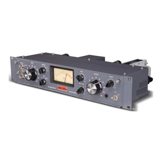
- Page 1 Retro Instruments, Inc. User’s Manual Tube Limiting Amplifier...
- Page 2 Retro Instruments, Inc. Tube Limiting Amplifier User’s Manual 2008 Retro Instruments, Inc. P.O. Box 5066 Modesto, CA 95352-5066 USA (209) 810-3344...
- Page 3 All rights reserved. No part of this document may be reproduced, transmitted, transcribed, stored in a retrieval system, or translated into any language in any form by any means without the written authorization of Retro Instruments, Inc. Printed in U.S.A.
-
Page 4: Table Of Contents
Contents Section 1 Description 1.1 Your Limiter 1.2 Applications 1.3 Specifications 1.4 Safety Considerations Section 2 Installation 2.1 Operating Environment 2.2 Power Connections 2.2.1 AC Line Voltage Selection 2.2.2 Fuse 2.2.3 Line Cord 2.3 Input Connection 2.4 Output Connection 2.5 Stereo Link 2.6 Grounding Section 3 Operation... - Page 5 4.1.9 Test Facilities Power Supply Circuit Board 4.2.1 Mains Input 4.2.2 Power Transformer 4.2.3 5Y3 High Voltage Rectifier 4.2.4 OB2 Gas Discharge Tube 4.2.5 Bleeder Resistor Section 5 Alignment and Maintenance Gain Reduction Meter Zero Internal Balance Test Switch Balancing the 6BC8 Gain Reduction Stage Balancing the Amplifier Stage Noise and Distortion Tests Frequency Response Tests...
-
Page 6: Your Limiter
The 176 is great for tracking, mixing and multibuss compression applications. Possibly the best application for the 176 is use on the stereo buss, buffing it to a glossy finish. The Retro 176 adjusts tone in a way that equalization cannot. -
Page 7: Safety Considerations
1.5 Safety Considerations The Retro 176 is to be used in a metal equipment rack with adequate ventilation. The vacuum tubes become hot. The AC mains power should be disconnected prior to servicing. For safety, the front door of the 176 is equipped with an interlock switch that interrupts the AC mains power when the door is opened. -
Page 8: Operating Environment
Section 2 Installation 2.1 Operating Environment Mount the 176 in a standard 19” equipment rack. Always install the bottom rack screws first to support the unit. Please allow room above the top ventilation holes and above the tubes. Additionally, there are ventilation holes on the sides to draw in cool air. Be aware of the heat sources in your rack to allow proper cooling. -
Page 9: Line Cord
2.2.3 Line Cord You can use a compatible IEC power cable for 100-120 Volts or 200-240 Volts per your country’s specification. Europe Australia 2.3 Input Connection Audio Input is a standard female XLR connector. It is transformer balanced and floating, meaning there is no path to ground from pin 2 and 3. -
Page 10: Stereo Link
Coupling Jack 2.6 Grounding The 176 is primarily grounded through the AC Mains. For safety, do not disable the AC ground. The chassis is also grounded through the rack ears to the rack. The XLR connectors are grounded on pin 1. Pin 1 is only used to drain the shield of the audio cable on one end of the cable. -
Page 11: Power Switch, Indicators And Interlock
If the fuse is blown, the likely cause is the fuse itself or a damaged 5Y3 rectifier tube. After a minute the meter should read near zero in the GR setting. The 176 is now ready to use. 3.2 Amplifier Active/Bypass Switch This switch lets you easily evaluate what the 176 is doing. -
Page 12: Attack And Release Controls
The Attack knob has a pull switch that disables the Retro 176 program-controlled time constant. The original UA 175B and 176 have a single time constant. By pulling the Attack knob OUT you can have that mode. The program-controlled time-constant (with the knob IN) makes the Retro 176 gain reduction more natural, better controlling dynamics with less distortion. -
Page 13: Meter Select Switch
+4 dBm. It is simple to check your input and output levels for easy setup and A/B comparisons with the Bypass switch. The Input Meter is fed directly from the Input XLR. The Output Meter is fed directly from the 176 Output Control before the Amplifier Bypass switch. -
Page 14: Principles Of Operation
Section 4 Principles of Operation 4.1 Amplifier Circuit Board 4.1.1 Input Transformer Stage The Input from the Female XLR Input connector feeds the bypass side of the Bypass switch and the input pad and input transformer. The input pad provides 20 dB of loss and transforms the 600 Ohm input to the proper 120 Ohm transformer impedance. -
Page 15: Asymmetry Switch
Power Supply Circuit Board 4.3.1 Mains Input The AC Power enters the 176 through the IEC power receptacle. It travels to the fuse, the door interlock switch and the front panel User Power switch. Finally it reaches the Voltage Selector switch and the Power Transformer. -
Page 16: Ob2 Gas Discharge Tube
4.3.4 0B2 Gas Discharge Tube The 0B2 is a cold-cathode, glow discharge tube. In combination with a 10K Ohm resistor it provides a regulated 108 Volts to the 6BC8 gain reduction stage. It will glow orange or purple depending on the variety. This tube can fail two ways; it stops glowing and the gain reduction meter rises to +3, or the light dances in the tube causing a rumble or squeal in the audio signal. -
Page 17: Alignment And Maintenance
Section 5 Alignment and Maintenance Balance Test Switch Meter Zero Cathode Bal. Plate Bal. Amp. Bal. All adjustments should be performed by a qualified technician. 5.1 Gain Reduction Meter Zero Use a small Xcelite Greenie or precision adjustment tool to make internal adjustments. The Gain Reduction Meter can be adjusted to zero to compensate for normal aging of components over time. -
Page 18: Balancing The Amplifier Stage
5.5 Noise and Distortion Tests To check the noise of the 176, send a 1 KHz tone into the 176 and adjust for 3 dB of compression. Compression Ratio should be set to 12:1. Adjust the Output Level for a 0 dB reference on your analyzer. - Page 19 squeal or make other space-like sounds. Mostly, they will make sound when you tap them. A healthy tube may make a tink or bonk sound or nothing at all. An excessively microphonic tube will make spastic sounds when tapped which can help isolate an intermittently noisy tube.
-
Page 20: Schematics And Drawings
Section 6 Schematics and Drawings Board Layouts and Schematics... -
Page 21: Support And Service
Section 7 Support and Service Retro Instruments provides all levels of support and service for your product. 7.1 Service The Product Warranty outlines our responsibilities for defective products. We also provide parts and service beyond the warranty period. Before returning a product for repair, contact our service department by telephone at 209- 810-3344 or contact us through our service page at http://retroinstruments.com/... -
Page 22: Warranty
Retro Instruments products are warranted to be free of all defects in material and workmanship for one year from the date of purchase. Within the period of this warranty, Retro Instruments will replace or repair at no charge at its service facility any part which is defective in material or workmanship. This... -
Page 23: Factory Service Instructions
7.5 Factory Service Instructions To obtain factory service, complete this page and include it with the unit. Name ______________________________________ Company __________________________________ Shipping Address __________________________ City, State, Zip _____________________________ Phone Number ______________________ e-mail ________________________ Model _____________________ Serial Number _________________________ Describe Problem: Special Instructions:...
Need help?
Do you have a question about the 176 and is the answer not in the manual?
Questions and answers