Table of Contents
Advertisement
Contents
TITLE
3.1.2
3.1.4 Relative measurement mode ................ 15
................. 1
................. 1
................. 1
................. 4
................. 6
................. 7
................. 8
................. 8
................. 10
................. 11
................. 13
................. 13
................. 13
................. 14
................. 15
PAGE
Advertisement
Table of Contents

Related Manuals for TekPower TP40

Summary of Contents for TekPower TP40
-
Page 1: Table Of Contents
Contents TITLE PAGE …………….. 1 1. GENERAL INSTRUCTIONS …………….. 1 1.1 Precaution safety measures …………….. 1 1.1.1 Preliminary …………….. 4 1.1.2 During use …………….. 6 1.2 Symbols …………….. 7 1.3 Instructions …………….. 8 2. DESCRIPTION …………….. 8 2.1 Instrument Familiarization …………….. - Page 2 TITLE PAGE …………….. 15 3.1.5 True RMS measurement …………….. 16 3.2 Measurement Functions 3.2.1 AC and DC Voltage measurement …………….. 16 …………….. 19 3.2.2 Resistance measurement …………….. 21 3.2.3 Capacitance measurement …………….. 23 3.2.4 Continuity Check …………….. 26 3.2.5 Diode Test ……………..
- Page 3 TITLE PAGE …………….. 39 4.2.5 Continuity Check …………….. 40 4.2.6 Capacitance …………….. 40 4.2.7 Temperature …………….. 40 4.2.8 Current …………….. 41 5. MAINTENANCE …………….. 42 5.1 General maintenance …………….. 42 5.2 Fuse replacement …………….. 43 5.3 Battery replacement …………….. 44 6.
-
Page 4: General Instructions
1. GENERAL INSTRUCTIONS This instrument complies with IEC 61010-1: 2001, CAT Ⅲ 1000V and CAT Ⅵ 600V overvoltage standards. See Specifications. To get the best service from this instrument, read carefully this user's manual and respect the detailed safety precautions. International symbols used on the Meter and in this manual are explained in chapter 1.2. - Page 5 overvoltages appropriately low level. • high-voltage, low-energy source derived from highwinding resistance transformer, such as the high-voltage section of a copier. • Appliance, portable tools, and other household and similar loads. • Outlet and long branch Single-phase circuits. receptacle • Outlets at more than 10 CATⅡ...
- Page 6 • Feeders short branch circuits, distribution panel devices. • Lighting systems in larger buildings. • Appliance outlets with short connections service entrance. • Refers to the “origin of installation”; i.e., where low-voltage connection is made to utility power. • Electricity meters, primary overcurrent...
-
Page 7: During Use
― protection against the dangers of electric current. ― protection of the Multimeter against misuse. * For your own safety, only use the test probes supplied with the instrument. Before use, check that they are in good condition. 1.1.2 During use * If the meter is used near noise generating equipment, be aware that display may become unstable or indicate large errors. - Page 8 specification tables. * When the multimeter is linked to measurement circuits, do not touch unused terminals. * Caution when working with voltages above 60Vdc or 30Vac rms. Such voltages pose a shock hazard. * When using the probes, keep your fingers behind the finger guards.
-
Page 9: Symbols
power switching circuits, remember that high amplitude voltage pulses at the test points can damage the multimeter. Use of a TV filter will attenuate any such pulses. * Use just one 6F22 battery, properly installed in the Meter's battery case, to power the Meter. * Replace the battery as soon as the battery indicator ) appears. -
Page 10: Instructions
Earth ground Double insulated Fuse Conforms to European Union directives 1.3 Instructions * Remove test leads from the Meter before opening the Meter case or battery cover. * When servicing the Meter, use only specified replacement parts. * Before opening up the instrument, always disconnect from all sources of electric current and make sure you are not charged with static electricity, which may destroy internal components. -
Page 11: Description
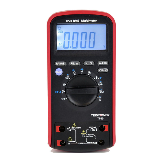
after the instrument is switched off. * If any faults or abnormalities are observed, take the instrument out of service and ensure that it cannot be used until it has been checked out. * If the meter is not going to be used for a long time, take out the battery and do not store the meter in high temperature or high humidity environment. - Page 12 measurements. ⑥ A Terminal receiving the red test lead for 6A,10A measurements. ⑦ COM Terminal receiving the black test lead as a common reference. 。 。 600mA MAX CAT III 1000V CAT IV 600V 10A MAX FUSED Figure 2-1...
-
Page 13: Lcd Display
2.2 LCD Display Figure 2-2 LCD screen is shown as in Figure 2-2, with its every symbol’s meaning shown as in the Table 1: Meaning Symbol Indicates negative readings Indicator for AC voltage or current Indicator for DC voltage or current... -
Page 14: Keypad
The meter is in the Autorange AUTO mode in which the meter automatically selects the range The Meter is in the data PC-LINK with the best resolution. transmission mode. No contact AC Voltage detect The meter is in Data Hold mode. - Page 15 Change to the second function. 1. At position Switches between Resistance measurement, Diode Test and Continuity check. 2. At A mA A position Switches between dc and ac current. 3. Power-up Option Disables automatic power-off feature. Keep press this key when power on. 2.3.2 Press it to enter and exit the Data Hold mode.
-
Page 16: Function Description
2.3.5 Hz % At V~, A, mA and A. 1. Press it to start the frequency counter. 2. Press it again to enter duty (load factor) mode. 3. Press it again to exit the frequency counter mode. 2.3.6 MAX/MIN This key is for measuring maximum value and minimum value. -
Page 17: Manual Ranging And
To enter and exit the Data Hold mode: 1. Press key (short press). Fixes the display on the current value, H is displayed. 2. A second short press returns the meter to normal mode. 3.1.2 Manual ranging and Autorange mode The Meter has both manual ranging and autorange options. -
Page 18: Battery Saver
3.1.3 Battery Saver The Meter enters the "sleep mode" and blanks the display if the Meter is on but not used for 15 minutes. Press the key or rotate the rotary switch to wake the meter up. To disable the Sleep mode, hold down the SELECT key while turning the meter on. -
Page 19: Measurement Functions
root-mean-square) values. Frequency range is up to 1KHz. 3.2 Measurement Functions 3.2.1 AC and DC Voltage measurement To avoid electrical shock and/or damage to the instrument, do not attempt to take any voltage measurement that might exceeds 1000Vdc or 1000Vac rms. To avoid electrical shock and/or damage to the instrument, do not apply more than 1000Vdc or 1000Vac rms between the common terminal and... - Page 20 even though you do not put test leads into input terminals For better accuracy when measuring the dc offset of an ac voltage, measure the ac voltage first. Note the ac voltage range, then manually select a dc voltage range equal to or higher than the ac range.
- Page 21 。 。 DC Voltage Figure3-1 Measuring AC and DC Voltage...
-
Page 22: Resistance Measurement
3.2.2 Resistance measurement To avoid electrical shock and/or damage to the instrument, disconnect circuit power discharge all high-voltage capacitors before measuring resistance. The Meter's resistance ranges are 600.0, 6.000k, 60.00k, 600.0k, 6.000M and 60.00M. To measure resistance (set up the Meter as shown in figure 3-2): 1. - Page 23 On 60M range, the meter may take a few seconds to stabilize reading. This is normal for high resistance measuring. When the input is not connected, i.e. at open circuit, the figure "OL" will be displayed for the overrange condition. 。...
-
Page 24: Capacitance Measurement
3.2.3 Capacitance measurement To avoid electrical shock and/or damage to the instrument, disconnect circuit power discharge all high-voltage capacitors before measuring capacitance. Use the dc voltage function to confirm that the capacitor is discharged. The Meter's capacitance ranges are 6.000nF, 60.00nF, 600.0nF, 6.000F, 60.00F, 600.0F, 6.000mF, 60.00mF. - Page 25 。 。 Figure 3-3 Measuring Capacitance...
-
Page 26: Continuity Check
3.2.4 Continuity Check To avoid electrical shock and/or damage to the instrument, disconnect circuit power discharge all high-voltage capacitors before testing for Continuity. To test for continuity (set up the Meter as shown in Figure 3-4): 1. Set the rotary switch to range. - Page 27 。 。...
- Page 28 。 。 Figure 3-4 Checking the Continuity...
-
Page 29: Diode Test
3.2.5 Diode Test To avoid electrical shock and/or damage to the instrument, disconnect circuit power discharge all high-voltage capacitors before testing diodes. To test a diode out of a circuit (set up the Meter as shown in Figure 3-3): 1. Set the rotary switch to range. - Page 30 。 。...
- Page 31 。 。 Figure 3-5 Measuring Capacitance...
-
Page 32: Frequency Measurement
3.2.6 Frequency and Duty Cycle measurement Do not measure Frequency on high voltage (>1000V) to avoid electrical shock hazard and/or damage to the instrument. The Meter can measure Frequency or Duty Cycle while making either an AC Voltage or AC Current measurement. To measure frequency or Duty Cycle: 1. -
Page 33: Temperature Measurement
3.2.7 Temperature measurement To avoid electrical shock and/or damage to the instrument, do not apply more than 250Vdc or 220Vac rms between the ° C terminal and the COM terminal. To avoid electrical shock, do not use this instrument when voltages at the measurement surface exceed 60v dc or 24v rms. -
Page 34: Current Measurement
3.2.8 Current measurement To avoid damage to the Meter or injury if the fuse blows, never attempt an in-circuit current measurement where the open-circuit potential to earth is greater than 1000V. To avoid damage to the meter, check the meter's fuse before proceeding. - Page 35 but will not damage the Meter.) 6. Turn on power to the circuit; then read the display. Be sure to note the measurement units at the right side of the display (A, mA or A). When only the figure "OL" displayed, it indicates overrange situation and the higher range has to be selected.
-
Page 36: Ncvhef
。 。 Figure 3-6 Measuring Current 3.2.9 NCV (Non-Contact Voltage detect) Set rotary switch to the ACV / range, Press the SELECT key to go NCV detect mode. Put the EF-DETECT AREA close to the AC power cable or the power socket, if AC electrical voltage is present, the Buzzer warning will sound,... -
Page 37: Pc Link
and the symbol bar “-“ will be displayed on the LCD. The lowest detect voltage is around 50V 50/60Hz. The LCD display EF, when detect the AC voltage signal, the LCD display ‘ - ’/‘ -- ’/‘ --- ’/‘ ---- ’ from weak to strong. This function is depending model. -
Page 38: Technical Specifications
view it in the Device Manager by following these steps: Right-click the My Computer icon on the Windows desktop, and then click Properties. Click the Hardware tab and then click Device Manager. Scroll through the list of installed devices till you locate the Ports (Com and LPT) entry. -
Page 39: Measurement Specifications
Temperature Coefficient: 0.1(specified accuracy) / ℃ (<18℃ or >28℃) MAX. Voltage between terminals and earth ground: 1000V AC rms or 1000V DC. Fuse Protection: A and mA: F 0.63A/1000V 10.338; A: F 10A/1000V 10.338. Sample Rate: 3 times/sec for digital data. Display: 3 5/6 digits LCD display. -
Page 40: Voltage
4.2.1 Voltage DCV: Range Resolution Accuracy 600mV 0.1mV ±(0.5% of rdg +5 digits) 10mV ±(0.8% of rdg +5 digits) 600V 100mV 1000V ±(1.0% of rdg +2 digits) ACV: Range Resolution Accuracy 600mV 0.1mV ±(1.0% of rdg + 5 digits) 10mV 600V 100mV 750V... -
Page 41: Frequency
2. Response for ACV: RMS measure, calibrated in rms of sine wave. 3. Overload Protection: 1000V dc or 1000V ac rms. 4. Input Impedance (Nominal): DC voltage: >10M; AC voltage: >10M 4.2.2 Frequency Logic frequency (1Hz-1MHz) Range Resolution Accuracy 99.99Hz 0.01 Hz 999.9Hz 0.1 Hz... -
Page 42: Resistance
4.2.3 Resistance Range Resolution Accuracy 600.0 0.1 ±(0.5% of rdg+3 digits) 6.000k 1 60.00k 10 ±(0.5% of rdg+2 digits) 600.0k 100 6.000M 1k 60.00M 10k ±(1.5% of rdg+5 digits) 4.2.4 Diode Test Range Resolution Test Condition Forward DC current approximately 1mA. 0.001V Reversed DC voltage approximately 1.5V. -
Page 43: Capacitance
4.2.6 Capacitance Range Resolution Accuracy ±(5.0% of rdg +20 digits) 60nF 10pF ±(3.0% of rdg +20 digits) 600nF 100pF 6F ± (5.0% of rdg+10 digits) 60F 10nF 600F 100nF 1F ±(5.0% of rdg +20 digits) 4.2.7 Temperature Range Resolution Accuracy -200~0℃... -
Page 44: Maintenance
ACA: Range Resolution Accuracy 600A 0.1A ±(1.8% of rdg+5 digits) 6000A 1A 60mA 0.01mA ±(1.8% of rdg+5 digits) 600mA 0.1mA ±(3.0% of rdg+8 digits) 10mA Above accuracies can be guaranteed within 5%~100% of the full range. The true RMS meter has residual value within 10 counts when the test leads are shorten, but that will not affect the accuracy of measurement. -
Page 45: General Maintenance
qualified to do so and have the relevant calibration, performance test, and service information. 5.1 General Maintenance To avoid electrical shock or damage to the meter, do not get water inside the case. Remove the test leads and any input signals before opening the case Periodically wipe the case with a damp cloth and mild detergent. -
Page 46: Battery Replacement
2. Disconnect test leads and/or any connectors from the terminals. 3. Use a screwdriver to unlock the four screws on the rear cover. 4. Take out the rear cover from the meter. 5. Remove the fuse by gently prying one end loose, then sliding the fuse out of its bracket. -
Page 47: Accessories
cover. 4. Take out the battery cover from the meter. 5. Remove the used battery. 6. Replace with one new 9V battery (6F22). 7. Rejoin the battery cover and tighten the screws. 6. ACCESSORIES Delivered with the multimeter: User's manual One piece ...
Need help?
Do you have a question about the TP40 and is the answer not in the manual?
Questions and answers
no, TP 7040 does not have four screws on the back instruction say to disconnect the four screws what do I do now?
If the TekPower TP40 does not have four screws on the back as instructed, do not attempt to open it. Opening the device incorrectly may cause damage or void warranties. Instead, refer to the manufacturer’s instructions or contact technical support for guidance.
This answer is automatically generated