
Summary of Contents for MSG FO045HS
- Page 1 Swimming Pool Mini Heat Pump Instruction of Operation and User Manual (End User’s Edition) Edition: UMN/202104/MILEU.
- Page 2 אזהרות זו חוברת את ושמרו זה במדריך שומות הר ההוראות כל אחר ועקבו בעיון קראו ותפעולו המכשיר לחיבור הנדרש המדיע כל את מכיל זה מדריך עתידי לשימוש וכללי הנחיות , זה מוצר אזהרות מוות או אחרות חמורות פציעות חשמלי שוק לרכוש...
- Page 3 Regulation (EU) n° 517/2014 of 16/04/14 on fluorinated greenhouse gases and repealing Regulation (EC) n°842/2006 Leakage checks 1. Operators of the equipment that contains fluorinated greenhouses gases in quantities of 5 tons of CO 2 , equivalent or more and not contained in foams, shall ensure that the equipment are well checked for leakage.
- Page 4 f) The dates and results of the checks have been carried out; g) If the equipment were decommissioned, the measures taken to recover and dispose of the fluorinated greenhouse gases. 2. The operator shall keep the records for at least five years, those who carry out the activities for operators shall keep copies of the records for at least five years.
-
Page 5: Table Of Contents
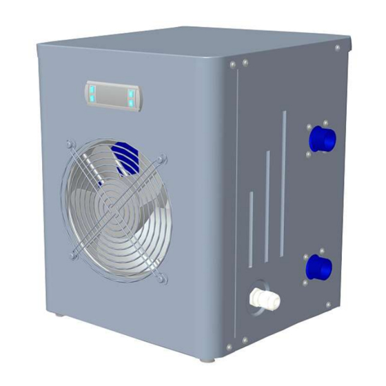
SWIMMING POOL MINI HEAT PUMP Instruction of Operation and Service Manual (End User’s Edition) INDEX Technical Specifications……………………………………………………………………….……..P5 Installation and connection……………………………………………………….……………….P6 Wiring circuit diagram………………………………………………………………………….….…P9 Operations of controller..………………………………………………………………….……….P10 Trouble shooting…………………………………………………………………………………….….P12 Exploded view and component list…………………………………………………………….P13 Maintenance……………………………………………………………………………………………..P15 Service & warranty…………………………………………………………………………………….P15 Thank you for selecting our Mini Heat Pump for your pool heating, it will heat your pool water and keep the constant temperature when the ambient air temperature at above 11 ℃. - Page 6 WARNING - Please always keep the heat pump at the places that well ventilated and away from anything which could cause fire. - Don’t weld the pipe if there is refrigerant inside. Please keep the heat pump out of the confined space when make gas charge.
-
Page 7: Technical Specifications
1. Technical Specifications 1.1 Technical data: Accordance with CE Standard, R32 /R410a refrigerant. Model No. FO045HS FO061HS Injection molded Anti-fire ABS Plastic or Cabinet material Galvanized steel <Performance at Air 27℃, Water 27℃, Relative Humidity 80%> Max Heating capacity 4.50 6.10... -
Page 8: Installation And Connection
Installation and connection ATTENTION: Please pay attention to the following rules when installing the heat pump: Any addition of chemicals must be carried out at the piping located downstream from the heat pump. Always hold the heat pump upright. If it has been held at certain angle more than 30°, wait at least 24 hours before starting the heat pump. - Page 9 2.3 Hose connection Notes: There ar e 2 hoses and 2 clamps supplied by the manufacturer and put in the accessories package. The upper connection port at heat pump’s right side is for water outlet, and the lower port is for water inlet.
- Page 10 ATTENTION: Make sure the power plug is Never pull out the power plug when Never use damaged electric wires secured your heat pump is running or unspecified electric wires. If the plug is not secure, it may cause Such improper operation may Otherwise it may cause an electric an electric shock, over-heating or fire cause an electric shock or a fire due...
-
Page 11: Wiring Circuit Diagram
Wiring circuit diagram Suitable for models: FO045HS FO061HS NOTES: (1) Above wiring circuit diagram is for reference only, due to consideration of universal use, there might be some difference from the actual circuit diagram, please refer to the one stuck on your heat pump. -
Page 12: Operations Of Controller
Operations of the controller 4.1 Buttons of the controller Outlet water temp. On / off Temp. regulator Up or down selection Settings When the heat pump is running, the LED display shows the water outlet temperature. LED 1 is on when compressor is running. LED 2 is on if the keys are locked to avoid children’s mis-operation. When the heat pump is switched off, it displays “OFF”... - Page 13 4.4 Fan motor defrosting 4.4.1 At defrosting, the compressor stops and fan motor keeps running, based on the regular time duration (Factory default setting is 12 min.). 4.4.2 Defrosting logic: When system detects ambient temp. ≤13℃, (Default value: 13℃), and compressor total running time for heating (Counted from the second of compressor starts, default value: 60 min.) reaches 60 min, it will enter regular defrosting mode: compressor stops and fan motor keeps running 12 min.
-
Page 14: Trouble Shooting
If this error appears 3 times within 30 minutes, the system will lock on it, the indication LED light “Running” will flash, and show error code “EL”, it can be only recovered by turning off the power supply. 4.6.3 Outgoing water temp. sensor failure If the system detects this temp. -
Page 15: Exploded View And Component List
1. Check the titanium heat exchanger Water stains on heat Water stains 1. Concreting; 2. Water leakage. pump unit. carefully if broken or defective. Exploded view and component list Suitable for models: FO045HS FO061HS... - Page 16 No. Components Components Top cover Base Pillar Titanium heat exchanger support Evaporator Side panel Gas discharge tube Gas returning tube Compressor Low pressure switch Needle valve Titanium heat exchanger Fan motor frame Gas collecting tube Compressor capacitance clip Capillary Compressor capacitance Outlet water temp.
-
Page 17: Maintenance
Maintenance (1) The users should check the water supply system regularly to avoid the air to enter the system and to cause low water flow, because it would reduce the performance and reliability of your heat pump unit. (2) Clean your pools and filtration system regularly to avoid the damage caused to your heat unit as a result of the dirty of clogged filter.
Need help?
Do you have a question about the FO045HS and is the answer not in the manual?
Questions and answers