Table of Contents
Advertisement
Quick Links
Advertisement
Table of Contents
Troubleshooting

Subscribe to Our Youtube Channel
Summary of Contents for Schiller ARGUS VCM
- Page 1 ARGUS VCM Vital Compact Monitor Service Handbook...
- Page 2 The information contained in this document is subject to change without notice. Schiller makes no warranty of any kind with regard to this material, including, but not limited to, the implied warranties or merchantability and fitness for a particular purpose.
-
Page 3: Table Of Contents
Contents ARGUS VCM Introduction Manual Overview ............................3 Related Documents............................3 Description of the ARGUS VCM monitor ....................3 Specifications Physical................................7 Electrical ................................7 Environmental ..............................7 Measurement Parameters ..........................8 Compliance ..............................10 Routine Maintenance Cleaning ................................11 Periodic Safety and Functional Checks ....................... - Page 4 ARGUS VCM Contents Packing For Shipment General Instructions ............................61 Returning the ARGUS VCM......................... 61 Repacking In Original Carton ........................61 Repacking In a Different Carton ........................62 System Processing Description System Overview ............................63 NIBP Processing ............................. 66 SpO2 Processing............................. 68 Temperature Processing..........................
- Page 5 Figure 25. Temperature Case Disassembly – Temperature Module ....................54 Figure 26. Temperature Case Disassembly........................... 55 Figure 27. ARGUS VCM Exploded View ............................56 Figure 28. ARGUS VCM Exploded View – Spare Parts........................ 58 Figure 29. ARGUS VCM System Block Diagram.......................... 63 Tables Table 1.
-
Page 6: Introduction
WARNING: Explosion hazard. Do not use ARGUS VCM in the presence of flammable anesthetics or gases. WARNING: Do not spray, pour, or spill any liquid on ARGUS VCM, its accessories, connectors, switches, or openings in the chassis. WARNING: Do not immerse ARGUS VCM or its accessories in liquid or clean with caustic or abrasive cleaners. - Page 7 CAUTION: When reassembling ARGUS VCM, over-tightening could strip out the screw holes in the cases, rendering it unusable. CAUTION: If any problem with ARGUS VCM built in an optional printer, check a printer’s door is closed well. Operating error may be caused if the cover is not closed correctly.
-
Page 8: Manual Overview
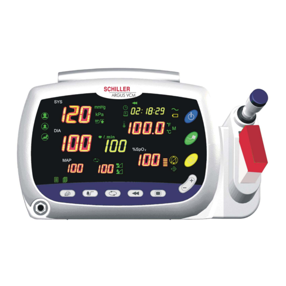
Read and understand all safety warnings and service notes printed in this service manual and the operator’s manual. This manual contains information about ARGUS VCM monitor. ARGUS VCM monitor includes the following configuration: Config. Features Config. - Page 9 24. Power Button 11. Auto Cycle Display 25. Battery Indicator 12. Auto Button 26. Charging/AC in Indicator 13. Pulse Tone/Alarm Volume Setting Indicators 27. Time Display 14. Review Button 28. Review Indicator Figure 1. ARGUS VCM Front Panel Service Manual ARGUS VCM...
- Page 10 ARGUS VCM Introduction AC IN 100-240V~, 50/60 Hz 28-38VA 1. Handle 4. Equipotential (Ground) 2. Air Ventilator 5. Battery Cover (Replacement) 3. AC Power Connector 6. RS-232 Data Interface Figure 2. ARGUS VCM Rear Panel Service Manual ARGUS VCM...
- Page 11 Introduction ARGUS VCM 1. Printer 3. NIBP hose connector 2. SpO sensor/cable connector Figure 3. ARGUS VCM Left Side Panel 1. Temperature probe 3. Probe holder 2. Probe cover 4. Temperature probe connector Figure 4. ARGUS VCM Right Side Panel...
-
Page 12: Specifications
Power 100Vac to 240Vac, 50 Hz/60 Hz, 28 to 38 VA Battery Type Lead acid Voltage/Capacity 6 V/ 4 Ampere-Hours Recharge 12 hours with ARGUS VCM Shelf Life 2 months, new fully charged battery Complies with 91/157/EEC Environmental Operation Temperature 10 °C (50 °F) to 40 °C (104 °F) -
Page 13: Measurement Parameters
Specification ARGUS VCM Measurement Parameters NIBP Pulse Rate Pulse Rate Range Adult/Pediatric/Neonatal 30 BPM to 220 BPM Pulse Rate Accuracy ±3 BPM or ±3%, whichever is greater NIBP (Non-Invasive Blood Pressure) Technique Oscillometric Measurement Measurement modes AUTO, MANUAL and STAT... - Page 14 20 BPM to 300 BPM ±3 digits Standards EN865:1997 Neonate specifications are shown for neonate sensors with ARGUS VCM. Saturation accuracy will vary by sensor type recommended by the manufacturer.. Specification applies to monitor performance and was validated with Biotek and Nellcor simulators...
-
Page 15: Compliance
Specification ARGUS VCM Compliance Item Compliant with Classification Class I (on AC power) Internally powered (on battery power) Type of Type BF – Applied part protection General Safety IEC60601-1:1998+A1:1991+A2:1995 General requirements for Safety and Essential Performance Alarms IEC60601-1-8:2001 Draft Alarm systems requirements, tests and guidances in medical... -
Page 16: Routine Maintenance
Functional Checks Batteries Environmental Protection WARNING: Do not spray or pour any liquid on the monitor or its accessories. Do not immerse ARGUS VCM or its accessories in liquid or clean with caustic or abrasive cleaners. Cleaning To clean , dampen a cloth with a commercial, nonabrasive cleaner and wipe ARGUS VCM the exterior surfaces lightly. -
Page 17: Functional Checks
2-year intervals. Refer to Disassembly Guide Section. CAUTION: If ARGUS VCM is to be stored for a period of 2 months or longer, it is recommended to notify service personnel to remove the battery from the monitor prior to storage. -
Page 18: Performance Verification
This section discusses the tests used to verify performance following repairs or during routine maintenance. All tests can be performed without removing covers. ARGUS VCM All tests except battery charge and battery performance tests must be performed as the last operation before the monitor is returned to the user. -
Page 19: Performance Tests
Performance Verification ARGUS VCM Performance Tests The battery charge and battery performance test should be performed before the monitor repairs whenever the battery is suspected as being a source of the problems. All other tests may be used following repairs or during routine maintenance (if required by your local institution). - Page 20 ARGUS VCM Performance Verification Power-On Self-Test 1. Connect the monitor to AC power source and verify Charging/AC in indicator is lit. 2. Observe the monitor front panel. With the monitor off, press Power button. The monitor must perform the following sequence.
- Page 21 Performance Verification ARGUS VCM Pulse Tone Volume Control 1. Connect the monitor to an AC power source. 2. Press Power button to turn the monitor on. 3. Connect SpO simulator to the pulse oximetry cable and connect the cable to the monitor.
- Page 22 ARGUS VCM Performance Verification Printer Test If Printer option installed, the following test procedures will verify printer performance. 1. Connect the monitor to an AC power source. 2. Press Power button to turn the monitor on. 3. Connect all necessary simulators to the monitor.
- Page 23 Performance Verification ARGUS VCM Measurement Parameter Operation Tests Pneumatic System Operation These tests verify the functionality of pneumatic system. ARGUS VCM 1. Place the neonatal cuff with a rigid PVC vessel (5cm diameter). Connect the cuff to NIBP cuff hose connector via the neonatal hose.
- Page 24 ARGUS VCM Performance Verification NIBP overpressure test 1. Connect the monitor to an AC power source, and then press Power button to turn the monitor on. 2. Press Mode button. Set to Adult patient type and NIBP target pressure, 270mmHg.
- Page 25 Performance Verification ARGUS VCM Temperature Operation If Temperature option installed, the following test procedures will verify temperature performance. 1. Connect the monitor to an AC power source. 2. Press Power button to turn the monitor on. 3. Connect temperature probe to the temperature connector of the monitor.
-
Page 26: Safety Tests
ARGUS VCM Performance Verification Safety Tests safety tests meet the standards of, and are performed in accordance with, ARGUS VCM IEC60601-1, Clause 19 (Second Edition, 1988; Amendment 1, 1991-11, Amendment 2, 1995-03), for instruments classified as Class I, Type BF. -
Page 27: Table 3. Enclosure Leakage Current
Performance Verification ARGUS VCM 3. Measure the leakage current between the foil and earth. Note: The analyzer leakage current indication must note exceed the values listed in Table Table 3. Enclosure Leakage Current Test Condition Allowable Leakage Current (microamps) Normal Condiction (NC) -
Page 28: Table 5. Patient Leakage Current Values-Mains Voltage On Applied Part
ARGUS VCM Performance Verification Patient Leakage Current - (Mains Voltage on the Applied Part) WARNING: AC mains voltage will be present on the applied part terminals during this test. Exercise caution to avoid electrical shock hazard. WARNING: Do not touch the patient leads clips or the simulator parts connected to patient leads during this test as an electrical shock will occur. -
Page 29: Table 6. Test Lead Combinations
Performance Verification ARGUS VCM 1. Configure the electrical safety analyzer as recommended by the electrical analyzer’s operating instructions. 2. Connect monitor’s AC mains power cord to the electrical analyzer as recommended by the electrical analyzer’s operating instructions. 3. Connect the patient test lead combination in table 6 to the appropriate input connector on the electrical analyzer. -
Page 30: Service Mode And Demo Mode
System Version The revision level of the system software displays: system software version, NIBP module version, SpO module version and Temperature module version. System version Temperature module version NIBP module version module version Figure 5. System Version Service Manual ARGUS VCM... - Page 31 Service Mode and Demo Mode ARGUS VCM Battery Voltage Level Current battery voltage level is displayed (unit of voltage: V). Figure 6. Battery Voltage Level NIBP Inflation Cycle The number of NIBP inflation cycles operated is displayed. Note: The values of NIBP inflation cycle may not be reset, but it will be reset to zero when a new Main PCB assembly is installed.
- Page 32 ARGUS VCM Service Mode and Demo Mode Total System Runtime Total Runtime displays the number of hours, rounded to the nearest hour, that the monitor has been operational. Note: The values of Total Runtime may not be reset, but it will be reset to zero when a new Main PCB assembly is installed.
-
Page 33: Table 8. Factory Default Settings For Argus Vcm
Service Mode and Demo Mode ARGUS VCM Factory default settings are described in Table 8. Table 8. Factory Default Settings for ARGUS VCM Parameter Ranges Defaults Systolic (mmHg) Neonatal Low: 25 to 115 High: 30 to 120 50, 100 Alarm Limits... - Page 34 ARGUS VCM Service Mode and Demo Mode Night Panel Night panel is used to adjust the light intensity of the display. With ‘Night Panel’ selected, - select ‘YES’ using only Up (+) selection button to degrade the light intensity between 21:00 to 06:00.
- Page 35 Service Mode and Demo Mode ARGUS VCM NIBP Pressure Test The real-time value of the system pneumatic pressure is displayed in mmHg. For more information, refer to Performance Verification section. With ‘NIBP Pressure Test’ selected, 1. Place the adult cuff with a rigid PVC vessel (9cm diameter). Connect the cuff and the adult hose to NIBP simulator.
-
Page 36: Demo Mode
Demo Mode The purpose of Demo mode is to show a visual presentation demonstrating how works. The following procedure is set to Demo mode. ARGUS VCM monitor 1. With the monitor powered off, press Power button and Alarm silence button simultaneously. - Page 37 Service Mode and Demo Mode ARGUS VCM This page is intentionally left blank. Service Manual ARGUS VCM...
-
Page 38: Firmware Download
This section is for the purpose of reloading Firmware (software?) into the monitor when the possibility of corrupted Firmware exists, or updating Firmware with a new system revision (system/device version). Call Schiller Technical Service Department for the latest version of Firmware and utility required. - Page 39 Firmware download ARGUS VCM 16. After completion of downloading, turn off the monitor. 17. Disconnect Firmware downloading cable from the monitor and PC. 18. Press Power button and NIBP start/stop button simultaneously to enter Service mode of the monitor. 19. Press Mode button to go to DEFAULT RESET.
-
Page 40: Troubleshooting
Obtaining Replacement Parts Schiller Technical Services provides technical assistance information and replacement parts. To obtain replacement parts, contact Schiller. Refer to parts by the part names and part numbers listed in Spare Parts section. Service Manual ARGUS VCM... -
Page 41: Troubleshooting Guide
Power problems are related to AC and/or Battery as follows. If the action requires replacement of the components, refer to Disassembly Guide. CAUTION: Electrical shock hazard. Disconnect a power cord from ARGUS VCM before attempting to open or disassemble ARGUS VCM. - Page 42 ARGUS VCM Troubleshooting Display The followings are symptoms of problems relating to non-functioning displays, and recommended actions. If the action requires replacement of a PCB assembly or module, refer to Disassembly Guide. 1. Display is totally black (no data is visible) after system powers up.
- Page 43 Troubleshooting ARGUS VCM Buttons The following is a symptom of problems and recommended actions relating to buttons. If the action requires replacement of a PCB assembly, refer to Disassembly Guide. 1. Buttons do not respond and/or buttons are operating with pressed.
- Page 44 ARGUS VCM Troubleshooting Performance The followings are symptoms of problems and recommended actions relating to SpO operational performance. If the action requires replacement of a PCB or module, refer to Disassembly Guide. 1. No displays (blank) on SpO display. 1-1. Replace SpO module.
- Page 45 Troubleshooting ARGUS VCM Printer The followings are symptoms of problems and recommended actions related to printing. If the action requires replacement of a PCB or module, refer to Disassembly Guide. 1. Print setting indicator does not light after system powers up.
- Page 46 ARGUS VCM Troubleshooting Others The followings are symptoms of problems and recommended actions that may happen related to operating the monitor. If the action requires replacement of a PCB or module, refer to Disassembly Guide. 1. No operation but Network indicator flashing after system powers up.
-
Page 47: Table 10. Technical Error Codes
Troubleshooting ARGUS VCM Error Codes When detects an error condition, the monitor will attempt to show an error ARGUS VCM code on the display screen. If such an error occurs during the monitoring operation, the monitor will sound a low- priority alarm. -
Page 48: Disassembly Guide
Battery Replacement Monitor Disassembly WARNING: Do not place ARGUS VCM into operation after repair or maintenance until Performance, Safety Tests and NIBP Calibration listed in this service manual have been performed. Failure of these tests could result in erroneous readings. -
Page 49: Replacement Level Supported
Disassembly Guide ARGUS VCM ARGUS VCM Front Case Rear Case Temperature Case Battery Cover Temperature Board Main Board C1-1 A1-1 B1-1 Temperature Module Rubber Button Battery A1-2 SMPS Module Temperature Pod B2-1 A1-3 SMPS Holder FND Module B2-2 Connector Box... -
Page 50: Prior To Disassembly
ARGUS VCM Disassembly Guide Prior to Disassembly 1. Turn off by pressing the Power On/Off switch. ARGUS VCM 2. Disconnect the monitor from the AC power source Fuse Replacement 1. After Step B2, remove 2 AC main fuses (F1, F2: 250V/2A) out of the socket if required. -
Page 51: Monitor Disassembly
Disassembly Guide ARGUS VCM Monitor Disassembly This section describes the steps to separate the front and rear case assemblies. Figure 17. Monitor Disassembly Table 11. Part Descriptions – Monitor Assembly Part Codes Descriptions Front case assembly (A) Rear case assembly (B) -
Page 52: Table 12. Part Descriptions - Front Case Assembly
ARGUS VCM Disassembly Guide Front Case Disassembly (A) This section describes the items that may be removed on the front case assembly. Figure 18. Front Case Disassembly Table 12. Part Descriptions – Front Case Assembly Part Codes Descriptions T0024-0 Front case... -
Page 53: Table 13. Part Descriptions - Main Bd, Spo2, Fnd Modules Assembly
Disassembly Guide ARGUS VCM Figure 19. Main BD, SpO , FND modules Disassembly Table 13. Part Descriptions – Main BD, SpO , FND Modules Assembly Part Codes Descriptions M4019-0 FND module T0025-0 connector box P1028-0 Main BD M0001-0 module S8007-0 Screw 3 ×... -
Page 54: Table 14. Part Descriptions - Overlay, Nibp Cuff Hose Connector
ARGUS VCM Disassembly Guide Figure 20. Front Case Disassembly – Overlay, NIBP cuff hose connector Table 14. Part Descriptions – Overlay, NIBP Cuff Hose Connector Part Codes Descriptions T0024-0 Front case T8005-0 ~ T8012-0 Front overlay T4104-0 NIBP cuff hose connector A3. -
Page 55: Table 15. Part Descriptions - Battery, Smps Assembly
Disassembly Guide ARGUS VCM Rear Case Disassembly This section describes the items that may be removed on the front case assembly. Figure 21. Rear Case Disassembly- Battery, SMPS Table 15. Part Descriptions – Battery, SMPS Assembly Part Codes Descriptions M2010-0... -
Page 56: Table 16. Part Descriptions - Nibp Module Assembly
ARGUS VCM Disassembly Guide Figure 22. Rear Case Disassembly- NIBP module Table 16. Part Descriptions – NIBP Module Assembly Part Codes Descriptions M0005-0 NIBP module S8007-0 Screw 3 × 6 S8070-0 Screw 3 × 8 (flat-head) S8097-0 Nut M3 B3. NIBP module disassembly 1. -
Page 57: Table 17. Part Descriptions - Printer Assembly
Disassembly Guide ARGUS VCM Figure 23. Rear Case Disassembly- Printer Table 17. Part Descriptions – Printer Assembly Part Codes Descriptions M4020-0 Printer S8090-0 Screw 3 × 8 3 (1) S8093-0 Screw 3 × 25 0 (2) * ( ) refers to the number of required screws if a print option is not installed in. -
Page 58: Table 18. Part Descriptions - Speaker, Handle, Etc Assembly
ARGUS VCM Disassembly Guide Figure 24. Rear Case Disassembly – Speaker, Handle, etc Table 18. Part Descriptions – Speaker, Handle, etc Assembly Part Codes Descriptions E9007-0 Speaker T0027-0 Handle S8066-0 Screw 3 × 5 (tapping) S8096-0 Screw 3 × 25 (tapping) B5. -
Page 59: Table 19. Part Descriptions - Temperature Module Assembly
Disassembly Guide ARGUS VCM Temperature Case Disassembly This section describes the items that may be removed on the temperature case assembly. Figure 25. Temperature Case Disassembly – Temperature Module Table 19. Part Descriptions – Temperature Module Assembly Part Codes Descriptions... -
Page 60: Table 20. Part Descriptions - Temperature Case Assembly
ARGUS VCM Disassembly Guide Figure 26. Temperature Case Disassembly Table 20. Part Descriptions – Temperature Case Assembly Part Codes Descriptions T0030-0 Temperature case T0031-0 Temperature probe holder S8090-0 Screw 3 × 8 S8002-0 Screw 3 × 8 (with washer) C2. Temperature case disassembly 1. - Page 61 Disassembly Guide ARGUS VCM Figure 27. ARGUS VCM Exploded View Service Manual ARGUS VCM...
-
Page 62: Spare Parts
Figure 8. Obtaining Replacement Parts Schiller Technical Service provides technical assistance information and replacement parts. To obtain replacement parts, contact Schiller. Refer to parts by the part names and part numbers. Service Manual ARGUS VCM... -
Page 63: Parts List
ARGUS VCM Parts List Schiller Technical Service provides technical assistance information and replacement parts. To obtain replacement parts, contact Schiller. Refer to parts by part numbers and part names. Figure 28. ARGUS VCM Exploded View – Spare Parts Service Manual... -
Page 64: Table 21. Argus Vcm Parts List
ARGUS VCM Spare Parts Table 21. ARGUS VCM Parts List Part Code Item Cases T0024-0 Front case T0025-0 connector box T0026-0 Rear case T0027-0 Handle T0029-0 SMPS holder T0030-0 Temperature case T0031-0 Temperature probe holder Structure Components T8005-0 Front overlay / NST... - Page 65 Spare Parts ARGUS VCM Part Code Item W0110-0 Serial wire / 9-pin W0111-0 Temperature wire / 5-pin W0112-0 Printer wire / 6-pin Screws / Spacers S8007-0 Screw 3 × 6 S8090-0 Screw 3 × 8 S8002-0 Screw 3 × 8 (with washer) S8091-0 Screw 3 ×...
-
Page 66: Packing For Shipment
Pack the monitor carefully. Failure to follow the instructions in this section may result in loss or damage not covered by the Schiller warranty. If the original shipping carton is not available, use another suitable carton; North American customers may call Schiller Technical Services to obtain a shipping carton. -
Page 67: Repacking In A Different Carton
Packing For Shipment ARGUS VCM Repacking In a Different Carton If the original carton is not available, use the following procedure to pack ARGUS VCM 1. Place the monitor in a plastic bag. 2. Locate a corrugated cardboard shipping carton with at least 200 pounds per square inch (psi) bursting strength. -
Page 68: System Processing Description
Connector NIBP Module Printer Speaker NIBP Pump Figure 29. ARGUS VCM System Block Diagram is a multi-function the monitor for use on adult, pediatric and ARGUS VCM monitor neonatal patients; non-invasive blood pressures, arterial oxygen saturation, pulse rate, and temperature. - Page 69 DC. Battery A lead-acid battery is used in the ARGUS VCM. It is rated at 6 volts DC, 4 amp hours. When new and fully charged, the battery will operate the monitor for 2 hours. A new battery will last 10 minutes from the time the low battery alarm is declared until the unit is shut down due to battery depletion.
- Page 70 ARGUS VCM System Processing Description Slave MCU Slave MCU is Toshiba TMP86PM47U. Slave MCU is mainly used for display driver. Slave MCU checks on Battery voltage level to transfer the level to Main MCU, and also it controls SMPS function during Firmware downloading mode.
-
Page 71: Nibp Processing
System Processing Description ARGUS VCM NIBP Processing Overview The oscillometric technique does not use Korotkoff sounds to determine blood pressure. The oscillometric technique monitors the changes in cuff pressure caused by the flow of blood through the artery. The monitor inflates the cuff to a pressure that occludes the artery. - Page 72 ARGUS VCM System Processing Description On clinical trial perspective, overall system accuracy is not easy to be determined. The clinical trial test protocols have been tried and have been described in many treatises, and international standards. So, there are many methods to determine the overall system accuracy of Automated Sphygmomanometer using the oscillometric method.
-
Page 73: Spo2 Processing
System Processing Description ARGUS VCM Processing Overview Pulse oximetry works by applying a sensor to a pulsating arteriolar vascular bed. The sensor contains a dual light source and photodetector. Bone, tissue, pigmentation, and venous vessels normally absorb a constant amount of light over time. The arteriolar bed normally pulsates and absorbs variable amounts of light during systole and diastole, as blood volume increases and decreases. - Page 74 ARGUS VCM System Processing Description Temperature PCO2 2,3-DPG Fetal Hb Temperature PCO2 2,3-DPG (mmHg) Oxyhemoglobin Dissociation Curve Functional versus Fractional Saturation This monitor measures functional saturation — oxygenated hemoglobin expressed as a percentage of the hemoglobin that can transport oxygen. It does not detect significant amounts of dysfunctional hemoglobin, such as carboxyhemoglobin or methemoglobin.
-
Page 75: Temperature Processing
3 minutes, and axillary in approximately five minutes. Measuring Principle The ARGUS VCM temperature probe utilizes a negative temperature coefficient (NTC) thermistor and control circuitry in combination with the temperature module’s predictive algorithm to calculate patient temperatures. - Page 78 CH-6341 Baar, Switzerland e-mail: sales@schiller.ch Web: www.schiller.ch Article Number 2.540041 Rev. a Issue Date: 10. September 2004 Headquarters: SCHILLER AG, Altgasse 68, CH-6341 Baar, Switzerland, Phone: +41 (0)41 766 42 42, Fax: +41 (0)41 761 08 80, e-mail: sales@schiller.ch REF: A7055-0...
Need help?
Do you have a question about the ARGUS VCM and is the answer not in the manual?
Questions and answers