Table of Contents
Advertisement
Available languages
Available languages
Quick Links
Advertisement
Table of Contents

Subscribe to Our Youtube Channel
Related Manuals for hydro-s 7029988

Summary of Contents for hydro-s 7029988
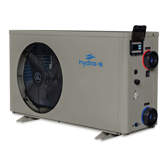
- Page 1 7029988 Hydro-S Heat pump 230V type 5 horizontal R32 7029989 Hydro-S Heat pump 230V type 8 horizontal R32 7029990 Hydro-S Heat pump 230V type 10 horizontal R32 7029991 Hydro-S Heat pump 230V type 12 horizontal R32 Swimming Pool Heat Pump User and Service manual Polish ●English ●...
- Page 2 Index/Spis treści CO2 Regulation (EU)/ Regulacje CO2 (EU)........1-3 Polski………………………………………………………………………………………….4-27 English………………………………………………………………………………………28-50 Deutsch…………………………………………………………………………………….51-72...
- Page 3 Regulacje (EU) n°517/2014 z 16/04/14 na temat fluorowanego gazu cieplarnianego i unieważnienie (EC) n° 842/2006 Kontrole szczelności Operator sprzętu który zawiera odpowiednik 5 ton fluorowanego gazu cieplarnianego, lub większa ilość oraz musi podlegać sprawdzenie sprzętu pod kątem szczelności. 2. Dla sprzętu zawierającego fluorowany gaz cieplarniany w ilości 5 ton lub więcej, ale mniej niż...
- Page 4 Regulation (EU) n° 517/2014 of 16/04/14 on fluorinated greenhouse gases and repealing Regulation (EC) n° 842/2006 Leak checks 1. Operators of equipment that contains fluorinated greenhouses gases in quantities of 5 tons of CO , equivalent more and not contained in foams shall ensure that the equipment is checked for leaks. For equipment that contains fluorinated greenhouse gases in quantities of 5 tons of equivalent or more, but of less than 50 tons of...
- Page 5 Verordnung (EU) Nr. 517/2014 vom 16/04/14 über fluorierte Treibhausgase und Verordnung (EG) zur Aufhebung Nr. 842/2006 Dichtheitsprüfung 1. Die Betreiber von den Geräte, die die fluorierte Treibhausgase in Mengen von 5 Tonnen CO -Äquivalent oder mehr enthalten und nicht in Schäumen enthalten, müssen sicherstellen, dass das Gerät auf Dichtheit überprüft wird. 2.
- Page 6 9. Konserwacja 10. Gwarancja i zwrot Dziękujemy za zakup pompy ciepła Hydro-S do basenów kąpielowych, umożliwia ona nagrzanie wody w basenie i utrzymanie jej stałej temperatury przy temperaturze otoczenia wynoszącej od 7 do 43℃. UWAGA: Instrukcja ta zawiera wszystkie informacje niezbędne do podłączenia i użytkowania zakupionej pompy ciepła.
-
Page 7: Specyfikacja Techniczna
1. Specyfikacja techniczna 1.1 Dane techniczne pomp grzewczych Hydro-S Model Hydro-S 5 Hydro-S 8 Hydro-S 10 Hydro-S 12 Numer katalogowy 7029988 7029989 7029990 7029991 * Wydajność na powietrzu 28 ℃, woda 28 ℃, wilgotność 80% Wydajność grzewcza 11.5 Pobór energii 1.17... - Page 8 2. Wymiary (mm) Model: Hydro-S 5 Model: Hydro-S 8,Hydro-S 10...
- Page 9 Model: Hydro-S 12...
-
Page 10: Montaż I Podłączenie
3. Montaż i podłączenie 3.1 Uwagi ogólne Producent odpowiada za dostarczenie produktu. Pozostałe komponenty, włącznie z obejściem by-pass o ile jest ono konieczne, muszą być dostarczone przez użytkownika lub instalatora. Uwaga: Podczas montażu i instalacji pompy należy postępować zgodnie z podanymi poniżej wskazówkami: 1. - Page 11 3.3 Odległość od basenu kąpielowego Pompę ciepła najlepiej zainstalować na obszarze o promieniu 7,5 metra od basenu kąpielowego. Im większa odległość pompy od basenu, tym większa utrata ciepła przez rurociągi. Rurociągi zwykle znajdują się pod ziemią, dlatego też straty cieplne są niskie dla odległości do 30 metrów (odległość 15 metrów od i do pompy, łączna odległość...
- Page 12 3.5 Rozmieszczenie standardowe Uwaga: Przedstawiony montaż jest tylko przykładowym rozwiązaniem. 3.6 Ustawienie obejścia by-pass Proszę wykonać poniższe kroki, aby dostosować obejście: 1. Wybierz 1 szeroko otwarte. Zawór 2 i zawór 3 zamknięty. Zawór 1 2. Otwórz zawór 2 i o połowę zawór 3, następnie zawór 1 powoli zamknij, aby Zawór 2 zwiększyć...
- Page 13 3.7 Podłączenie zasilania Uwaga: Mimo, iż pompa grzewcza posiada izolację elektryczną względem pozostałej części systemu basenu kąpielowego, nie oznacza to, że nie zapobiega ona kontaktowi prądu z wodą basenie kąpielowym. Nadal niezbędne jest zainstalowanie uziemienia chroniącego przed spięciami w urządzeniu. Zawsze trzeba zapewnić odpowiednie uziemienie zgodnie z lokalnymi przepisami a podłączenie musi być...
- Page 14 a woda może ulegać skraplaniu na płetwach parownika. Przy wysokiej wilgotności, skraplaniu może ulegać nawet kilka litrów wody na godzinę. Czasem zjawisko to jest błędnie uznawane za wyciek wody. 4. Akcesoria 4.1 Wykaz akcesoriów Podstawka antywibracyjna, 4 szt. Syfon odprowadzający, 2 szt. Rury kanalizacyjne,, 2 szt.
- Page 15 Przyłącze doprowadzające/odprowadzające wodę 1. Zamontowanie dwóch złączy tak, jak to pokazano na zdjęciu. 2. Przykręcenie ich do przyłącza doprowadzającego/odprowadzającego wodę Okablowanie kabli 1. Otwórz osłonę zacisków 2. Zamocuj drut zasilający na złączach Okablowanie pompy wodnej 2. Za pomocą łączników 1 i 2 można pilotować 1.
- Page 16 5. Kable elektryczne 5.1 SCHEMAT OKABLOWANIA POMPY CIEPŁA DO BASENOW KĄPIELOWYCH Hydro-S 5,Hydro-8,Hydro-S 10...
- Page 17 Hydro-S 12 UWAGA: (1) Powyższy schemat okablowania ma wyłącznie charakter orientacyjny, prosimy o podłączenie urządzenia zgodnie z diagramem. (2) Pompa grzewcza do basenów kąpielowych musi zostać odpowiednio uziemiona mimo, iż wymiennik ciepła został odizolowany od reszty urządzenia. Wykonanie uziemienia jest nadal wymagane w celu ochrony przed zwarciami napięcia w urządzeniu.
- Page 18 Obsługa (1) Instrukcja obsługi HEATING GRZANIE DEFROSTING ODMRAŻANIE TIMER OFF WYŁĄCZANIE TIMERA TIMER ON WŁĄCZANIE TIMERA WARNING OSTRZEŻENIE USTAW (2) Uruchamianie basenowej pompy podgrzewającej Naciśnij aby uruchomić pompę podgrzewającą, wyświetlacz LED pokaże wejściową temperaturę wody oraz bieżący tryb pracy po 5 s. (3) Zatrzymywanie basenowej pompy podgrzewającej Naciśnij ponownie aby zatrzymać...
- Page 19 ** USTAWIANIE MINUTY ** Naciśnij (USTAW) aby wejść do ustawiania MINUT, błyska ”MM”, następnie naciśnij aby ustawić minuty od 0 do 59. (6) Ustawianie WŁĄCZANIA TIMERA Naciśnij przycisk (USTAW), następnie naciśnij dwukrotnie przycisk aby wejść do ustawiania WŁĄCZANIA TIMERA. Kiedy zobaczysz początek wyświetlania czasu naciśnij (USTAW) aby potwierdzić...
- Page 20 włączenia TIMERA oraz czas wyłączenia TIMERA, przycisk nie działa. 5. Ustawianie parametrów Ta część powinna być ustawiana wyłącznie przez wykwalifikowanego serwisanta serwisu posprzedażnego lub utrzymaniowego. (1) Naciśnij (USTAW) + w tym samym czasie przez 5 sekund, wyświetlacz błyska, (2) Naciśnij aby wybrać...
-
Page 21: Usterki I Ich Usuwanie
7. Usterki i ich usuwanie 7.1 Kody błędów wyświetlane na wyświetlaczu ciekłokrystalicznym LED panelu sterowania Usterka Kod błędu Przyczyny Rozwiązanie Ochrona niskiej Temperatura otoczenia temperatury otoczenia jest zbyt niska Awaria czujnika Czujnik na zewnątrz lub Sprawdzenie lub wymiana czujnika. temperatury dopływającej nastąpiło zwarcie. - Page 22 Bezpiecznik wysokiego 1. Zbyt dużo gazu 1. Usunięcie nadmiar gazu ciśnienia chłodniczego chłodniczego z systemu gazowego 2. Zbyt mała cyrkulacja jednostki grzewczej . powierza 2. Oczyszczenie wymiennika powietrza Bezpiecznik niskiego 1. Zbyt mało gazy 1. Sprawdzenie czy nie nastąpił ciśnienia chłodniczego.
- Page 23 7.2 Pozostałe usterki i ich usuwanie (niewyświetlane na wyświetlaczu ciekłokrystalicznym LED panelu sterującego) Usterka Objawy Przyczyny Rozwiązanie Wyświetlacz Sprawdzenie podłączonych kabli i ciekłokrystaliczny LED Brak zasilania automatycznego wyłącznika jeśli panelu sterowania jest jest on podłączony. czarny. Na wyświetlaczu ciekłokrystalicznym LED Pompa grzewcza znajduje Należy ponownie włączyć...
- Page 24 8. Schemat budowy pompy 8. 1 Widok urządzenia rozebranego Model: Hydro-S 5...
- Page 25 No. Części zamienne No. Części zamienne 1 Rura (tytanowy wymiennik do kapilary) 27 Kondensator silnika wentylatora 2 Rura wydechowa 28 Tylny grill 3 Przełącznik wysokiego ciśnienia 29 Lewy panel 4 Powrót rurociągów gazowych 30 Wspornik silnika wentylatora 5 Przełącznik niskiego ciśnienia 31 Panel izolacji 6 Zawór gazu 32 Silnik wentylatora...
- Page 26 9. Konserwacja (1) Zalecane jest regularne sprawdzanie rurociągu doprowadzającego wodę celem uniknięcia przedostania się powietrza do układu lub wystąpienia zmniejszonego przepływu wody, gdyż czynniki te ograniczają wydajność i niezawodność jednostki ciepła. (2) Należy systematycznie czyścić basen i system filtrów celem uniknięcia uszkodzeń jednostki ciepła wskutek zabrudzonego lub zablokowanego filtra.
-
Page 27: Ograniczona Gwarancja
10. Gwarancja i zwrot 10.1 Gwarancja OGRANICZONA GWARANCJA Dziękujemy za zakup naszej pompy ciepła. Oferowana przez nas gwarancja obejmuje wszystkie błędy produkcyjne i materiałów dla wszystkich części przez okres dwóch lat od chwili zakupu. Gwarancja ta jest ograniczona do pierwszego kupującego, zatem nie może zostać przeniesiona i nie ma zastosowania wobec produktów, które zostały przeniesione ze swojego pierwotnego miejsca instalacji. - Page 28 10.2 Formularz zwrotu RMA Firma: Data : Adres: Miasto: Kraj: pocztowy: Kontakt: Tel : E-mail: Faks : Kontakt: Data : Zastrzeżone do użytku wewnętrznego RMA #: Podpis: Data : Zwrot dla: Czy załączono kopię faktury klienta? Czy do wniosku RMA dołączono inne dokumenty? Opis dokumentów: Nr modelu: Nr faktury:...
- Page 29 Procedura zwrotów: 1. Prosimy o uzyskanie u nas w pierwszej kolejności numeru RMA w celu sprawdzenia czy przestrzegane były wymogi dotyczące instalacji i eksploatacji określone w niniejszej instrukcji. 2. W tym celu należy skontaktować się z naszym działem RMA i uzyskanie formularza RMA. 3.
- Page 30 9. Maintenance 10. Warranty and returns Thank you for using Hydro-S swimming pool heat pump for your pool heating, it will heat your pool water and keep the constant temperature when the air ambient temperature is at 7 to 43℃...
-
Page 31: Specifications
1.Specifications Technical data Hydro-S pool heat pumps Model Hydro-S 5 Hydro-S 8 Hydro-S 10 Hydro-S 12 Part number 7029988 7029989 7029990 7029991 * Heating Capacity at Air 28℃, Water 28℃,Humidity 80% Heating capacity 11.5 Power consumption 1.17 2.02 2.45 C.O.P. -
Page 32: Dimension (Mm)
2. Dimension (mm) Model:Hydro-S 5 Model:Hydro-S 8,Hydro-S 10... -
Page 33: Installation And Connection
Model:Hydro-S 12 3. Installation and connection 3.1 Notes The factory supplies only the heat pump. All other components, including a bypass if necessary, must be provided by the user or the installer. Attention: Please observe the following rules when installing the heat pump: 1. -
Page 34: Check-Valve Installation
3.2 Heat pump placement The unit will work properly in any desired location as long as the following three items are present: 1. Fresh air – 2. Electricity – 3. Swimming pool filters The unit may be installed in virtually any outdoor location as long as the specified minimum distances to other objects are maintained (see drawing below). - Page 35 3.5 Typical arrangement Note: This arrangement is only an illustrative example.
-
Page 36: Electrical Connection
3.6 Adjusting the bypass Use the following procedure to adjust the bypass: 1.Valve 1 wide open. Valve 2 & valve 3 closed. 2.Slowly open valve 2 & valve 3 by To pool From pool half, then close the valve 1 slowly to increase the water flow to valve 2 &... - Page 37 After all connections have been made and checked, carry out the following procedure: 1. Switch on the filter pump. Check for leaks and verify that water is flowing from and to the swimming pool. 2. Connect power to the heat pump and press the On/Off button on the electronic control panel.
- Page 38 4. Accessories 4.1 Accessories list Anti-vibration base, 4 pcs Draining jet, 2 pcs Water drainage pipes, 2 pcs 4.2 Accessories Installation Anti-vibration bases 1. Take out 4 Anti-vibration bases 2. Put them one by one on the bottom of machine like the picture. Draining jet 1.
- Page 39 Water Inlet & outlet junction 1. Install the two joints like the picture shows 2. Screw them onto the water Inlet & outlet junction Cable wiring 1. Open the terminal cover 2. Fix the power supply wire on joints Water pump wiring 1.
-
Page 40: Electrical Wiring
5. Electrical Wiring 5.1 SWIMMING POOL HEAT PUMP WIRING DIADRAM Hydro-S 5,Hydro-S 8,Hydro-10... - Page 41 Hydro-S 12 NOTE: (1)Above electrical wiring diagram only for your reference, please subject machine posted the wiring diagram. (2)The swimming pool heat pump must be connected ground wire well, although the unit heat exchanger is electrically isolated from the rest of the unit .Grounding the unit is still required to protect you against short circuits inside the unit .Bonding is also required.
-
Page 42: Operation
6.Operation (1) Guide for operation (2)Start the pool heat pump Press to start the heat pump, the LED display will show the inlet water temperature and current working mode after 5s. (3) Stop the pool heat pump Press once again to stop the heat pump, the LED display shows ‘OFF’ (4) Water temperature setting Press to set the desired water in temperature in current working mode, then Press... - Page 43 displaying on controller ,Press to confirm to enter into TIMER ON setting interface , finally press to adjust the starting time. (7) TIMER OFF Setting Press button ,then press button 3 times to enter into “ TIME OFF” setting . When you see the stopping time displaying on controller ,Press to confirm to enter into TIMER OFF setting interface , finally press to adjust the stopping time .
- Page 44 (3) Press again to enter into interface (4) Press to adjust the value setting. (5) Finally press once again to save the data or press to save and quick-exit the parameter setting . Parameter Meaning Range Default Remarks To set the entering water 7-35°C 28°C Not adjustable...
-
Page 45: Troubleshooting
7. Troubleshooting 7.1 Error code display on LED wire controller Malfunction Error Reason Solution code Low ambient temperature protection Ambient temperature is too low Check or change the sensor Inlet water temperature sensor failure The sensor in open or short circuit Check or change the sensor Outlet water temperature sensor The sensor in open or... - Page 46 7.2 Other Malfunctions and Solutions (No display on wire controller) Malfunctions Observing Reasons Solution LED wire controller Check cable and circuit No power supply no display. breaker if it is connected LED wire controller. Heat pump under standby Startup heat pump to run. displays the actual time.
- Page 47 8. Exploded Diagram 8. 1 Exploded Diagram Model:Hydro-S 5...
- Page 48 No. Part Name No. Part Name 1 Pipe (Titanium exchanger to Capillary ) 27 Fan motor capacitor 2 Exhaust pipe 28 Back grill 3 High pressure switch 29 Left grill 4 Back gas piping 30 Fan motor bracket 5 Low pressure switch 31 Isolation panel 6 Gas Vavle 32 Fan motor...
-
Page 49: Maintenance
9. Maintenance (1) You should check the water supply system regularly to avoid the air entering the system and occurrence of low water flow, because it would reduce the performance and reliability of HP unit. (2) Clean your pools and filtration system regularly to avoid the damage of the unit as a result of the dirty of clogged filter. -
Page 50: Warranty And Returns
10. Warranty and returns 10.1 Warranty LIMITED WARRANTY Thank you for purchasing a heat pump from us. This warranty covers manufacturing and material defects in all components for a period of two years after the date of purchase. This warranty is limited to the original purchaser in the retail sector. It is not transferable, and it is not applicable to products that have been removed from their original installation location. -
Page 51: Rma Request Form
10.2 RMA request form Company: Date: Street address: City/town: Postal Country: code: Contact: Phone: E-mail: Fax: Contact: Date: Reserved for internal use RMA no.: Assigned by: Date: Reason for return: Copy of customer invoice included? RMA request accompanied by other documents? Description of the documents: Model no.: Invoice no.:... - Page 52 All products received by us that lack labels or that have incorrect, incomplete or unreadable labels will be refused, with return shipping costs to be borne by you. All packages delivered to us with clearly visible damage will be refused immediately. Before returning products, please check that the products you intend to return to us are the same as the products for which an RMA number was issued.
- Page 53 Wartung 10. Gewährleistung und RMA Danke dass Sie Hydro-S für das Beheizen ihres Schwimmbeckens benutzen. Es wird ihr Poolwasser aufheizen und auf einer konstanten Temperatur halten, wenn die Außentemperatur zwischen 7 und 43℃ liegt. ACHTUNG: Dieses Handbuch beinhaltet alle Informationen die für die Benutzung und die Installation ihrer Wärmepumpe erforderlich sind.
-
Page 54: Technische Daten
1. Technische Daten 1.1 Technische Daten der Hydro-S Wärmepumpe,R32 Modell Hydro-S 5 Hydro-S 8 Hydro-S 10 Hydro-S 12 Artikelnummer 7029988 7029989 7029990 7029991 * Leistung bei Air 28 ℃, Wasser 28 ℃, Luftfeuchtigkeit 80% Heizleistung 11.5 Leistungsaufnahme 1.17 2.02 2.45 * Leistung bei Air 15 ℃... - Page 55 2. Ausmaße (mm) Model:Hydro-S 5 Model:Hydro-S 8,Hydro-S 10...
-
Page 56: Installation Und Anschluss
Model:Hydro-S 12 3. Installation und Anschluss 3.1 Anmerkungen Die Fabrik liefert nur die Wärmepumpe. Alle anderen Komponenten, einschließlich eines Bypasses wenn nötig, müssen durch den Benutzer oder den Installateur gestellt werden. Achtung: Bitte halten Sie beim Installieren der Wärmepumpe folgende Regeln ein: 1. - Page 57 3.2 Positionierung der Wärmepumpe Die Einheit wird an jeder gewünschten Position richtig arbeiten, solange die folgenden drei Elemente vorhanden sind: 1. Frische Luft – 2. Elektrizität – 3. Schwimmbecken-filter Die Einheit kann praktisch an jedem Standort im Außenbereich installiert werden, solange die angegebenen Mindestabstände zu anderen Objekten eingehalten werden (siehe Zeichnung unten).
- Page 58 Garantie gedeckt. 3.5 Typische Anordnung Anmerkung: Diese Anordnung ist nur ein illustratives Beispiel.
- Page 59 3.6 Einstellen des Bypasses Bitte nehmen Sie die folgenden Schritte ein, um den Bypass anzupassen: 1.Valve 1 weit offen. Ventil 2 & Ventil 3 geschlossen. 2. Ventil 2 & Ventil 3 um die Hälfte öffnen, dann das Ventil 1 langsam schließen, um den Wasserfluss zum Ventil 2 &...
- Page 60 1. Schalten Sie die Filterpumpe aus. Prüfen Sie ob es ein Leck gibt, und stellen Sie sicher dass das Wasser vom und zum Schwimmbecken fließt. 2. Schließen Sie die Wärmepumpe an ein Stromnetz an und betätigen Sie die On/Off Taste auf dem Bedienfeld.
- Page 61 4.2 Installation des Zubehörs Vibrationsdämpfer 1. Nehmen Sie 4 Vibrationsdämpfer heraus 2. Legen Sie einen nach dem anderen wie im Bild gezeigt unter die Maschine. Entwässerungsdüse 1. Installieren Sie die Entwässerungsdüse unter dem unteren Bedienfeld. 2. Verbinden Sie sie mit einem Wasserschlauch, um das Wasser abzuleiten.
-
Page 62: Elektrische Verkabelung
5. Elektrische Verkabelung 5.1 VERKABELUNGSDIAGRAMM DER SCHWIMMBECKEN-WÄRMEPUMPE Hydro-S 5,Hydro-S 8,,Hydro-S 10... - Page 63 Hydro-S 12 HINWEIS: (1) Der Schaltplan dient nur zu ihrer Referenz (2) Die Schwimmbecken-Wärmepumpe muss gut geerdet sein, auch wenn der Wärmewechsler vom Rest der Einheit elektrisch isoliert ist. Die Erdung ist dennoch wichtig, um Sie vor Kurzschlüssen im Inneren des Gerätes zu schützen.
- Page 64 Display Controller-Betrieb (1) Anleitung des Betriebs (2) Die Lachewärmepumpe anstellen Dücken Sie , um die Wärmepumpe anzustellen. Die LED Aneige zeigt die Wassertemperatur des Eingangs und den gegenwärtigen Modus in 5s. (3) Die Lachewärmepumpe aufhören Dücken Sie noch einmal, um die Lachewärmepumpe aufzuhören. Die LED Aneige zeigt ‘OFF’. (4) Die Wassertemperatur einstellen Dücken Sie oder...
- Page 65 (6) TIMER AUF einstellen Zuerst drücken Sie , dann drücken Sie zwei mal, um die TIMER AUF einzustellen. Wenn Sie sehen, dass die Anlaßzeit auf dem Kontroller angezeigt, dann bestätigen Sie bitte mit , dass wir in die TIMER AUF Einstellungsschnittstelle treten.
- Page 66 (1) Drücken Sie in 5 Sekunde gleichzeitig, Anzeige Blitze. (2) Mit oder wählen Sie die Parameter, die Sie einstellen möchten. (3) Mit treten Sie noch einmal in Schnittstellen ein. (4) Mit oder justieren Sie die Werteinstellung. Zuletzt drücken Sie noch einmal, um die Data zu speichern oder mit speichern Sie die Parameter Einstellung und zurückgehen.
-
Page 67: Fehlerbehebung
7. Fehlerbehebung 7.1 Fehlercodeanzeige auf einer LED-Kabelsteuerung Fehlfunktion Fehlerco Ursache Lösungsweg Schutz vor niedriger La température ambiante est Umgebungstemperatur trop basse Fehlfunktion beim Sensor Überprüfen oder wechseln Sie den für die Wassereintritts- Drahtbruch oder Kurzschluss Sensor temperatur Fehlfunktion beim Sensor Überprüfen oder wechseln Sie den für die Wasseraustritts- Drahtbruch oder Kurzschluss... - Page 68 Wasserflussmenge ist nicht Überprüfen Sie die Fehlfunktion bei der genug, die Wasserdurchflussmenge und Wasserein- und Wasserdruckdifferenz ist zu schauen Sie nach ob das Wasser Austrittstemperatur gering gestaut ist Die Kabelverbindung ist nicht Überprüfen Sie die Kabelverbindung Kommunikationsfehler 7.2 Andere Fehlfunktionen und ihre Lösung (werden nicht auf der LED-Kabelsteuerung angezeigt) Fehlfunktion Anzeichen Ursachen...
- Page 69 8. Explosionszeichnung und Wartung 8. 1 Explosionszeichnung Hydro-S 5...
- Page 70 No. Ersatzteile No. Ersatzteile 1 Rohr (Titanaustauscher zu Kapillare) 27 Kondensator des Lüftermotors 2 Auspuff 28 Hinterer Grill 3 Hochdruckschalter 29 Linker Grill 4 Gasleitungen hinten 30 Lüftermotorhalterung 5 Niederdruckschalter 31 Isolierfeld 6 Gasventil 32 Lüftermotor 7 Kompressor 33 Ventilatorflügel 8 Dämpferfüße des Kompressors 34 Frontblende 9 Wassereintrittstemp.
-
Page 71: Wartung
9. Wartung Sie sollten das Wasserzufuhrsystem regelmäßig überprüfen, um zu vermeiden dass Luft in das System eindringt und geringe Wasserflussmenge verursacht, denn das würde die Leistung und Zuverlässigkeit der HP-Einheit reduzieren. Reinigen Sie ihr Becken und Filtersystem regelmäßig um Schäden an der Einheit durch verschmutzte Filter zu vermeiden. -
Page 72: Beschränkte Gewährleistung
10. Gewährleistung und RMA (Warenrücksendegenehmigung) 10.1 Gewährleistung BESCHRÄNKTE GEWÄHRLEISTUNG Danke für den Kauf unserer Wärmepumpe. Wir garantieren für einen Zeitraum von zwei Jahren ab dem Datum des Erwerbs im Einzelhandel, dass alle Teile hinsichtlich Material und Ausführung frei von Herstellungsmängeln sind. Diese Gewährleistung beschränkt sich auf den ersten Einzelhandelskäufer, ist nicht übertragbar und gilt nicht für Produkte, die von ihrem ursprünglichen Einbauort entfernt wurden. - Page 73 10.2 RMA Antragsformular Firma: Datum: Adresse: Ort: PLZ: Land: Ansprechpartner: Tel.: E-Mail: Fax: Ansprechpartner: Datum: Interne Verwendung RMA-Nummer: Ausgestellt von: Datum: Rücksendung wegen: Kopie der Kundenrechnung beigelegt? Andere Unterlagen dem RMA-Antrag beigelegt? Beschreibung Unterlagen: Modell Nr.: Rechnung Nr.: Seriennr.: Rechnungsdatum Problem:...
- Page 74 Richtlinien zur Gewährleistungsreparatur: 1. Rücksendungen sind "Fracht vorausbezahlt" zu senden. Alle Rücksendungsgebühren sind von Ihnen zu tragen. 2. Für die Rückgabe von Produkten ist eine vorherige Genehmigung erforderlich. Nicht für die Rückgabe genehmigte Produkte werden Ihnen auf Ihre Kosten zurückgeschickt. 3.
- Page 76 A0111HYSR302...
Need help?
Do you have a question about the 7029988 and is the answer not in the manual?
Questions and answers