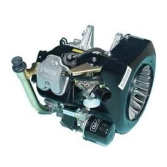
Club Car FE290 Repair And Rebuild Manual

Club Car FE290 Repair And Rebuild Manual

Engines and drivetrain components
Hide thumbs Also See for FE290:
Table of Contents

Advertisement

Engine Models:
• FE290
• FE350
• FE400
REPAIR
AND
REBUILD
MANUAL
Engines
and
Drivetrain
Components
Gasoline and Diesel
Vehicles
Unitized Transaxle Models:
• MC008C-ES00
• MC008C-FS00
• MC010C-BS00 (with Differential Lock)
• MC012C-AS00 (with Differential Lock)
• MC012C-BS00 (with Differential Lock)
MANUAL NUMBER 102396501
EDITION CODE 0904A00000
All-Wheel Drive:
• Transmission
• Front Differential
• Rear Differential

Advertisement

Table of Contents
loading
Need help?

Need help?

Do you have a question about the FE290 and is the answer not in the manual?

Questions and answers

Kevin
April 20, 2025

FE 290 D new fuel lines new fuel pump overhauled motor seems to run only a half rpm short on power?

1 comments:
Mr. Anderson
May 10, 2025

A Club Car FE290 engine running at half RPM and lacking power after installing new fuel lines and a new fuel pump could be caused by a fuel delivery issue. Possible causes include:

1. Air leak in the fuel lines causing improper fuel flow.
2. Incorrect installation of the fuel pump or lines restricting fuel supply.
3. A clogged or gummed-up carburetor not delivering enough fuel to the engine.
4. Blocked or improperly vented fuel tank preventing proper fuel flow.

These issues can prevent the engine from receiving enough fuel, leading to low RPM and power loss.

This answer is automatically generated

Dean
January 25, 2025

FE290 engine. Seems like crankshaft gear and camshaft gear are binding, causing difficulty for starter to turn engine?

Summary of Contents for Club Car FE290

  • Page 1 MANUAL Engines Drivetrain Components Gasoline and Diesel Vehicles Engine Models: Unitized Transaxle Models: All-Wheel Drive: • FE290 • MC008C-ES00 • Transmission • FE350 • MC008C-FS00 • Front Differential • FE400 • MC010C-BS00 (with Differential Lock) • Rear Differential • MC012C-AS00 (with Differential Lock) •...
  • Page 3 Club Car distributor/dealer representative or by a Club Car factory- trained technician. It is the policy of Club Car, Inc. to assist its distributors and dealers in continually updating their service knowl- edge and facilities so they can provide prompt and efficient service for vehicle owners. Regional technical rep- resentatives, vehicle service seminars, periodic service bulletins, maintenance and service manuals, and other service publications also represent Club Car’s continuing commitment to customer support.
  • Page 4 NOTE: This manual represents the most current information at the time of publication. Club Car, Inc. is continually working to further improve our other products. These improvements may affect servic- ing procedures.
  • Page 5: Table Of Contents

    SECTION 1 – SAFETY General Warning ..........................SECTION 2 – FE290 ENGINE General Information .......................... Special Engine Service Tools Available from Club Car ..............Recommended Replacement Parts for Engine Teardown ............Before Servicing ........................... Mechanical Systems ........................Cylinder Components ........................
  • Page 6 Adjustments and Settings ......................2-47 SECTION 3 – FE350 ENGINE General Information ......................... Special Engine Service Tools Available From Club Car ..............Recommended Replacement Parts For Engine Teardown ............Before Servicing ........................... Mechanical Systems ........................Cylinder Components ........................Cylinder Head ..........................
  • Page 7 3-48 Adjustment and Settings ....................... 3-49 SECTION 4 – FE400 ENGINE General Information .......................... Special Engine Service Tools Available From Club Car ..............Recommended Replacement Parts For Engine Teardown ............Before Servicing ........................... Cylinder Head ........................... General Information ........................Muffler Removal and Installation ......................
  • Page 8 SECTION 5 – MC008C-ES00 AND MC008C-FS00 UNITIZED TRANSAXLES General Information ......................... Transaxle Models and Identification ....................Axle Shaft ............................Unitized Transaxle Removal ......................Unitized Transaxle Disassembly ...................... Component Disassembly ......................... Governor Gear Disassembly ......................Differential Gear Case Disassembly .................... Shifter Fork Disassembly ......................5-11 Synchronizer Gear Disassembly ....................
  • Page 9 Unitized Transaxle Component Inspection ..................6-13 Component Assembly ........................6-14 Idler Shaft Assembly ........................6-14 Intermediate Gear Assembly ......................6-14 Synchronizer Gear Assembly ....................... 6-14 Shifter Fork Assembly ........................6-16 Differential Gear Case Assembly ....................6-17 Governor Gear Assembly ......................6-19 Differential Gear Lock Housing Assembly ..................
  • Page 10 Lubrication ............................7-29 SECTION 8 – TRANSMISSION MODELS 420317 AND 420682 General Information ......................... Model Identification .......................... Service Fixture ..........................Transmission Removal ........................Transmission Disassembly ......................Input Shaft Disassembly ......................Input Shaft Assembly ........................Intermediate Shaft Disassembly ....................Output Shaft Disassembly ......................8-12 Shifter Shaft Removal ........................
  • Page 11 Rear Differential Disassembly ......................10-2 Pinion Gear Removal ........................10-4 Ring Gear Removal ........................10-6 Clutch Carrier Assembly ....................... 10-7 Ring Gear Installation ........................10-8 Pinion Gear Installation ......................... 10-9 Rear Differential Assembly ......................10-9 Axle Shafts and Differential Installation .................... 10-10 SECTION i –...
  • Page 12 Page x Repair and Rebuild Manual – Engines and Drivetrain Components...
  • Page 13: Section 1 - Safety

    SECTION 1 – SAFETY To ensure the safety of those servicing Club Car vehicles, and to protect the vehicles from damage resulting from improper service or maintenance, the procedures in this manual must be followed. It is important to note that throughout this manual there are statements contained within boxes labeled DANGER, WARNING, or CAUTION.
  • Page 14 SAFETY General Warning ∆ WARNING • Follow the procedures exactly as stated in this manual, and heed all DANGER, WARNING, and CAUTION statements in this manual as well as those on the vehicle. • Only trained technicians should service or repair the vehicle. Anyone doing even simple repairs or service should have knowledge and experience in electrical and mechanical repair.
  • Page 15 SAFETY General Warning AS SEEN FROM PASSENGER SIDE OF VEHICLE Remove negative cable first. DISCONNECT BATTERY CABLES BEFORE WORKING ON VEHICLE Figure 1-1 Gasoline Vehicle Repair and Rebuild Manual – Engines and Drivetrain Components Page 1-3...
  • Page 17: Section 2 - Fe290 Engine

    GENERAL INFORMATION See General Warning on page 1-1. The FE290 gasoline engine is produced for pedal-start vehicles. This 4-cycle, single cylinder engine is designed for reliable heavy-duty service. It has two major component assemblies: the cylinder assembly and the crankcase assembly. The FE290 engine is provided with the MC008C-ES00 transaxle. See Transaxle Models and Identification on page 5-1 .
  • Page 18: Recommended Replacement Parts For Engine Teardown

    FE290 ENGINE Special Engine Service Tools Available from Club Car RECOMMENDED REPLACEMENT PARTS FOR ENGINE TEARDOWN DESCRIPTION CCI P/N Air Filter 1015426 Carburetor insulator to throttle bracket gasket 1016439 Carburetor to intake manifold gasket 1016438 Drive belt 1016203 Exhaust gasket 1015330 Exhaust system (muffler)
  • Page 19 FE290 ENGINE Special Engine Service Tools Available from Club Car Dirt Clean the engine thoroughly before servicing it. See following CAUTION. CAUTION • Before removal and disassembly, clean the engine. Any dirt entering the engine, carburetor, or other parts will work as an abrasive and shorten the life of the engine. Before installing a new part, clean off any dust or metal filings.
  • Page 20: Cylinder Components

    High Flash-point Solvent Use a high flash-point solvent when cleaning parts. Club Car recommends Stoddard solvent (generic name), a commercial solvent commonly available in North America. Always follow manufacturer and container direc- tions regarding the use of any solvent.
  • Page 21 FE290 ENGINE Cylinder Components EARLIER STYLE GOVERNOR CABLE CURRENT STYLE GOVERNOR CABLE Figure 2-1 Carburetor Removal 4. Remove nuts at carburetor intake pipe (5) and remove intake pipe (Figure 2-1, Page 2-5). See following CAUTION. CAUTION • Disconnect the governor linkage from the carburetor before attempting to remove the carburetor.
  • Page 22 FE290 ENGINE Cylinder Components Cylinder Shroud Removal, Continued: TYPICAL 2 PLACES TYPICAL 2 PLACES Figure 2-2 Exhaust System 7. Disconnect oil filler tube (20) from cylinder shroud by first removing the locknut (18), ground wire (17) and flange nut (10) (Figure 2-3, Page 2-6). See following NOTE.
  • Page 23: Rocker Arm And Push Rod Removal

    FE290 ENGINE Cylinder Components 8. Remove the eight bolts (14) and the two-ended bolts (11 and 15) (Figure 2-3, Page 2-6 and Figure 2-4, Page 2-6). 9. Take off the head shroud (13), the upper shroud (23) and the bracket (22) (Figure 2-3, Page 2-6 and Figure 2-4, Page 2-6).
  • Page 24: Valve Removal

    FE290 ENGINE Cylinder Components VALVE REMOVAL 1. Compress the valve spring with the valve spring compressor (5) (CCI P/N 101641101) and remove the collet halves (6) (Figure 2-9, Page 2-8). 2. Remove spring compressor and take out the upper retainer (7) and the spring (8).
  • Page 25: Cylinder Head Cleaning And Inspection

    FE290 ENGINE Cylinder Components Breather Valve (Reed Valve) Removal 1. Unscrew the mounting screw (1) and remove the back plate (2) and reed valve (3) (Figure 2-11, Page 2-9). For installation, see Breather Valve Installation on page 2-19. Figure 2-11 Reed Valve...
  • Page 26 FE290 ENGINE Cylinder Components Valve Guide Inspection, Continued: Measure each position in 2 places 90° apart. Figure 2-13 Combustion Chamber Figure 2-14 Measure I.D. of Valve Guides Valve Guide Replacement 1. With the combustion chamber side of the head facing up, drive the guide out of the head with a valve guide arbor (1) (CCI P/N 101641202) (Figure 2-15, Page 2-10).
  • Page 27: Valve Seats

    FE290 ENGINE Cylinder Components VALVE SEATS See General Warning on page 1-1. Valve Seat Inspection 1. Inspect the valve seats for damage. If the seats are warped or distorted beyond reconditioning, replace the cylinder head. 2. Use prussian blue metal die to coat the valve seat.
  • Page 28 Valve Seat Repair CAUTION • If you are unfamiliar with the following procedures, Club Car suggests that the cylinder head be taken to a professional engine machine shop for reconditioning. 1. Clean the cylinder head thoroughly. See Cylinder Head Cleaning and Inspection on page 2-9.
  • Page 29: Valves

    1. Inspect the valve head seating area (1) for erosion, nicks and warping, etc. (Figure 2-23, Page 2-13). NOTE: The valve seating surface angle for the FE290 engine is 45° (Figure 2-24, Page 2-14). 2. If the valve head seating area is worn, replace the valve.
  • Page 30 FE290 ENGINE Cylinder Components Visual Inspection, Continued: 4. Inspect the stem for obvious wear, discoloration, and stem end damage. 5. If the stem is obviously worn or discolored, replace the valve. 45° Figure 2-24 Valve Seating Surface Area Valve Head Thickness 1.
  • Page 31: Rocker Arm And Rocker Shaft Inspection

    FE290 ENGINE Cylinder Components Valve Stem Diameter 1. Using a micrometer, measure the diameter of the stem at several points along its length (Figure 2-26, Page 2-14). 2. If the outside diameter is less than the service limit of 0.2728 inch (6.930 mm) intake, 0.2722 inch (6.915 mm) exhaust, replace the valve.
  • Page 32: Push Rod Inspection

    FE290 ENGINE Cylinder Components Rocker Arm and Rocker Shaft Inspection, Continued: Measure each position in 2 places 90° apart. Measure each position in 2 places 90° apart. Figure 2-28 Measure I.D. of Rocker Arm Bearing Figure 2-29 Measure O.D. of Rocker Shaft PUSH ROD INSPECTION 1.
  • Page 33 FE290 ENGINE Cylinder Components Figure 2-31 Rocker Arm Assembly Figure 2-32 Cylinder Head Installation 3. Slide the washer (4) against the exhaust rocker and fit the E-ring (1) into the groove in the rocker shaft (2) (Figure 2-31, Page 2-17).
  • Page 34: Valve Clearance Check And Adjustment

    FE290 ENGINE Cylinder Components VALVE CLEARANCE CHECK AND ADJUSTMENT NOTE: Check and adjust clearance when the engine is cold. 1. Turn the crankshaft until the piston is at the top of the compression stroke. 2. Use a feeler gauge (1) to measure the clearance (2) between the adjuster screw (3) and the top of the valve stem (4) (Figure 2-34, Page 2-18 and Figure 2-35, Page 2-18).
  • Page 35: Installation Of Remaining Engine Components

    FE290 ENGINE Cylinder Components Breather Valve Installation 1. Installation is the reverse of removal. See Breather Valve (Reed Valve) Removal on page 2-9. NOTE: Place the reed valve on the seat so there is a slight gap (2) of 0.008 inch (0.203 mm) maximum between the valve and the seat (Figure 2-36, Page 2-19).
  • Page 36: Crankcase Components

    FE290 ENGINE Crankcase Components Installation Of Remaining Engine Components, Continued: NOTE: Before installing the plug, check the condition of the threads in the cylinder head. Soften deposits in cylinder head threads with penetrating oil and clean the threads with a tap if necessary.
  • Page 37 FE290 ENGINE Crankcase Components Oil Level Sensor Removal 1. Disconnect the oil level sensor wire (2) from the cord connector (1) (Figure 2-41, Page 2-21). 2. Remove the screw (3) from the wire clamp (4). 3. Remove the two mounting screws (8) from the inside of the crankcase cover and remove the oil level sen- sor and bracket.
  • Page 38: Camshaft And Tappets

    FE290 ENGINE Piston and Connecting Rod CAMSHAFT AND TAPPETS Camshaft Removal 1. Align timing marks before removing camshaft (Figure 2-42, Page 2-21). 2. Turn the engine upside down to keep tappets (1) from catching the cam lobes (Figure 2-42, Page 2-21).
  • Page 39 FE290 ENGINE Piston and Connecting Rod Piston and Connecting Rod Separation 1. Remove the two retaining rings holding the piston pin in place. 2. Remove the piston pin. Piston Inspection and Repair 1. Remove all deposits from the piston. 2. Clean the carbon from the piston ring grooves. See following CAUTION.
  • Page 40 FE290 ENGINE Piston and Connecting Rod Piston Ring Inspection, Continued: 4. Use a micrometer to measure the thickness of both piston rings at several points around the rings (Figure 2-48, Page 2-24). 5. If either ring thickness is less than 0.0566 inch (1.438 mm), replace the entire set of rings.
  • Page 41: Cylinder Block

    FE290 ENGINE Cylinder Block Connecting Rod Inspection 1. Clean and inspect the bearing surfaces of the connecting rod and cap. Replace parts if scored. 2. Use an inside micrometer or a telescoping gauge to measure the inside diameter of the connecting rod small bore at several points along its length (Figure 2-51, Page 2-25).
  • Page 42 FE290 ENGINE Cylinder Block Cylinder Block, Continued: • The standard bore diameter is 3.0700 - 3.0708 inches (77.980 - 78.000 mm). • The maximum cylinder bore diameter wear limit is 3.0735 inches (78.067 mm). • The maximum acceptable out of round cylinder bore is 0.0022 inch (0.056 mm).
  • Page 43: Ignition Coil And Flywheel

    FE290 ENGINE Ignition Coil and Flywheel CAUTION • The cylinder must be thoroughly cleaned after honing to eliminate all grit. IGNITION COIL AND FLYWHEEL See General Warning on page 1-1. Ignition Coil and Flywheel Removal 1. Loosen three screws and remove the remaining four screws attaching the flywheel housing, then remove the housing (Figure 2-55, Page 2-27).
  • Page 44 FE290 ENGINE Ignition Coil and Flywheel Ignition Coil Installation It is recommended that the ignition coil (CCI P/N 101909201) be replaced with engine teardown. 1. Installation is the reverse of removal. 2. Lightly tighten the two bolts (3), then use a bronze feeler gauge to adjust the ignition coil air gap to 0.012 inch (0.304 mm) (Figure 2-58, Page 2-28).
  • Page 45: Oil Pump

    FE290 ENGINE Oil Pump OIL PUMP See General Warning on page 1-1. Oil Pump Cover Removal 1. Remove the six screws (1) and take off the oil pump cover (2) (Figure 2-59, Page 2-28). 2. Peel off the oil pump cover gasket (3).
  • Page 46: Oil Pressure Relief Valve

    FE290 ENGINE Oil Pump OIL PRESSURE RELIEF VALVE Oil Pressure Relief Valve Removal 1. Remove the oil pump cover. See Oil Pump Cover Removal on page 2-29. 2. Remove the valve seat (1), ball (2) and spring (3) (Figure 2-64, Page 2-30).
  • Page 47: Crankshaft And Counterbalance

    FE290 ENGINE Crankshaft and Counterbalance SLOT TANG Figure 2-66 Install Inner Rotor Figure 2-67 Counterbalance Guide Shaft and O-Ring CRANKSHAFT AND COUNTERBALANCE See General Warning on page 1-1. Crankshaft and Counterbalance Removal 1. Remove the four nuts (1) and pull out the counterbalance guide shaft (2) and the O-Ring (3) (Figure 2-67, Page 2-31).
  • Page 48 FE290 ENGINE Crankshaft and Counterbalance Crankshaft and Counterbalance Disassembly, Continued: TYPICAL 4 PLACES Figure 2-68 Crankshaft and Counterbalance Figure 2-69 Inspect Link Rod GEAR YOKE HELICAL GEAR (CC P/N NO.1016418) SPUR GEAR PRESS RAM GEAR YOKE SIDE BLOCKS SIDE BLOCKS (2)
  • Page 49 FE290 ENGINE Crankshaft and Counterbalance Link Rod Inspection 1. Clean and inspect the link rod (1) bearing surfaces. If the bearing surface of the small end is scored or damaged, replace the link rod. If the large end bearing is scored or damaged, the bearing must be replaced (Figure 2-69, Page 2-32).
  • Page 50: Counterbalance Weight

    FE290 ENGINE Crankshaft and Counterbalance Link Rod Bushing Replacement, Continued: 0.039 in. (0.991 mm) Figure 2-74 Remove Bearing From Link Rod Figure 2-75 Install New Bearing Into Link Rod COUNTERBALANCE WEIGHT NOTE: The wrist pins are tightly pressed into the weight and normally require no maintenance.
  • Page 51 FE290 ENGINE Crankshaft and Counterbalance Measure each position Measure each position in in 2 places 90° apart. 2 places 90° apart. Figure 2-78 Measure Main Journals Figure 2-79 Measure Connecting Rod Journal Crankshaft Inspection 1. Clean and inspect the journals for scoring. Inspect the crankshaft gear for cracks, scoring or broken teeth.
  • Page 52: Oil Screen

    FE290 ENGINE Crankshaft and Counterbalance Undersized Connecting Rod The connecting rod journal can accept an undersized connecting rod with a 1.3779 inches (35.0 mm) inside diameter. Grinding the crankshaft is required before using the undersized connecting rod. 1. Have a reliable repair shop grind the crankshaft journal (A) (Figure 2-82, Page 2-36).
  • Page 53: Ball Bearing

    FE290 ENGINE Crankshaft and Counterbalance BALL BEARING Ball Bearing Removal 1. Remove the oil seal in the crankcase cover. See following NOTE. NOTE: Never reuse an oil seal. Replace the oil seal with a new one. 2. Place the crankcase cover (1) on a bench with its outside up (gasket surface against bench) (Figure 2-84, Page 2-36).
  • Page 54 FE290 ENGINE Crankshaft and Counterbalance Plain Bearing Surface Inspection Plain bearing surfaces are used for both ends of the camshaft and the flywheel end of the crankshaft. 1. Inspect the camshaft surfaces, one in the crankcase (3) (Figure 2-86, Page 2-38) (and the other in the crankcase cover (1) (Figure 2-87, Page 2-38).
  • Page 55: Piston And Connecting Rod Installation

    FE290 ENGINE Crankshaft and Counterbalance 1. Installation is the reverse of removal. See Crankshaft and Counterbalance Removal on page 2-31. 2. Tighten the four nuts (2) for counterbalance guide shaft to 50 in-lb (5.9 N·m) (Figure 2-67, Page 2-31). 3. If the link rod was removed from the PTO side of the crankshaft, support the crankweb as shown, slide the link rod onto the crankshaft, and install the key.
  • Page 56: Crankshaft Axial Play Adjustment

    4. Choose the next smaller shim from the table. Example: Measurement A is 15.87 mm and B is 17.66 mm. The correct crankshaft shim (5) is 1.53 mm. NOTE: Crankshaft shim sizes for FE290 engines range from 1.13 to 1.53mm. 5. Install the shim (5) on the crankshaft (6) (Figure 2-94, Page 2-41).
  • Page 57 FE290 ENGINE Crankshaft Axial Play Adjustment Figure 2-93 Determine Crankshaft Shim Size Figure 2-94 Install Shim on Crankshaft 16.25 14.50 14.55 14.60 14.65 14.75 14.80 14.70 Measurement (A) Measurements in Millimeters Figure 2-95 Crankshaft Shim Table Repair and Rebuild Manual – Engines and Drivetrain Components...
  • Page 58: Crankcase Cover Installation

    FE290 ENGINE Crankshaft Axial Play Adjustment Camshaft Installation CAUTION • When installing the camshaft, make sure that the tang (1) on the oil pump rotor seats in the slot (2) in end of the camshaft (Figure 2-96, Page 2-42). If the oil pump tang is not seated in the slot in the camshaft, serious engine damage will result.
  • Page 59: Engine Assembly

    FE290 ENGINE Engine Assembly Crankcase Cover Installation, Continued: Figure 2-98 Crankcase Cover Installation ENGINE ASSEMBLY See General Warning on page 1-1. CAUTION • Before assembly, make sure parts are clean. 1. Install cylinder head. See Cylinder Head Installation on page 2-16.
  • Page 60: Engine Installation

    FE290 ENGINE Engine Installation Engine Assembly, Continued: 4. Install ignition coil. See Ignition Coil Installation on page 2-28. 5. Install all remaining engine components. See Installation Of Remaining Engine Components on page 2-19. 6. Install a new spark plug, gap 0.027 to 0.031 inch (0.69 to 0.79 mm). Tighten to 20 ft-lb (27.1 N·m). See following NOTE.
  • Page 61: Service Specifications

    FE290 ENGINE Service Specifications SERVICE SPECIFICATIONS ITEM SERVICE LIMIT Breather reed valve (valve tip air gap) 0.008 in. (0.2 mm) max. Camshaft axial play 0.0137 in. (0.35 mm) Camshaft bearing 0.9080 in. (23.063 mm) inner diameter max. Camshaft cam lobes (exhaust, intake) 1.287 in.
  • Page 62: Specifications For Resizing Cylinder Bore

    FE290 ENGINE Service Specifications ITEM SERVICE LIMIT Rocker arm bearing 0.4754 in. (12.074 mm) inner diameter max. Rocker shaft 0.4704 in. (11.949 mm) outer diameter min. Support shaft 1.0199 in. (25.907 mm) outer diameter min. Valve clearance (exhaust, intake) 0.0047 in. (0.12 mm) standard Valve face angle (exhaust, intake) 45°...
  • Page 63: Adjustments And Settings

    FE290 ENGINE Service Specifications ADJUSTMENTS AND SETTINGS ITEM LIMITS Spark plug gap (standard) 0.027 to 0.031 in. (0.69 to 0.79 mm) Ignition coil air gap (standard) 0.012 in. (0.304 mm) Oil pressure (min.) at fast idle speed 45.5 psi (314 kPa) Oil filter: bypass-valve opening pressure...
  • Page 65: Section 3 - Fe350 Engine

    The FE350 engines may be provided with either the MC010C-BS00 or MC012C-AS00 transaxle. See Transaxle Models And Identification on page 6-1. SPECIAL ENGINE SERVICE TOOLS AVAILABLE FROM CLUB CAR DESCRIPTION CCI P/N...
  • Page 66: Recommended Replacement Parts For Engine Teardown

    FE350 ENGINE Special Engine Service Tools Available From Club Car RECOMMENDED REPLACEMENT PARTS FOR ENGINE TEARDOWN DESCRIPTION CCI P/N Air filter 1015426 Carburetor insulator to throttle bracket gasket 101973401 Carburetor to intake manifold gasket 1016438 Drive belt 102267101 Exhaust gasket 102270101 Exhaust system (muffler)
  • Page 67 FE350 ENGINE Special Engine Service Tools Available From Club Car Dirt Clean the engine thoroughly before servicing it. See following CAUTION. CAUTION • Before removal and disassembly, clean the engine. Any dirt entering the engine, carburetor, or other parts will work as an abrasive and shorten the life of the engine. Before installing a new part, clean off any dust or metal filings.
  • Page 68: Cylinder Components

    High Flash-point Solvent Use a high flash-point solvent when cleaning parts. Club Car recommends Stoddard solvent (generic name), a commercial solvent commonly available in North America. Always follow manufacturer and container direc- tions regarding the use of any solvent.
  • Page 69 FE350 ENGINE Cylinder Components EARLIER STYLE GOVERNOR CABLE END CURRENT STYLE GOVERNOR CABLE Figure 3-1 Carburetor Removal 1. Earlier Style Governor Cable End: 1.1. Remove cotter pin (3) and clevis pin (2) from throttle valve lever (Figure 3-1, Page 3-5). 2.
  • Page 70 FE350 ENGINE Cylinder Components Cylinder Shroud Removal, Continued: TYPICAL 2 PLACES TYPICAL 2 PLACES Figure 3-2 Muffler System - FE350 Engine 6. Disconnect oil filler tube (20) from cylinder shroud by first removing the locknut (18), ground wire (17) and flange nut (10) (Figure 3-3, Page 3-6).
  • Page 71: Rocker Arm And Push Rod Removal

    FE350 ENGINE Cylinder Components ROCKER ARM AND PUSH ROD REMOVAL NOTE: The FE350 engines are equipped with hydraulic lifters, which automatically eliminate all clearance in the valve train. Therefore, the rocker arms (3) and the push rods (5) do not need to be put back in their original positions (Figure 3-6, Page 3-7).
  • Page 72: Valve Removal

    FE350 ENGINE Cylinder Components VALVE REMOVAL 1. Compress the valve spring using a valve spring compressor (5) (CCI P/N 101641101) and remove the collet halves (6) (Figure 3-9, Page 3-8). 2. Remove spring compressor and take out the upper retainer (7) and the spring (8). 3.
  • Page 73: Cylinder Head Cleaning And Inspection

    FE350 ENGINE Cylinder Components Breather Valve (Reed Valve) Removal 1. Unscrew the mounting screw (1) and remove the back plate (2) and reed valve (3) (Figure 3-11, Page 3-9). For installation, see Breather Valve Installation on page 3-18. Figure 3-11 Reed Valve Figure 3-12 Check Flatness of Head Surface CYLINDER HEAD CLEANING AND INSPECTION 1.
  • Page 74: Valve Guides

    FE350 ENGINE Cylinder Components VALVE GUIDES Valve Guide Inspection 1. Measure the inside diameter of each guide with a telescoping gauge (Figure 3-14, Page 3-10). 2. If the inside diameter exceeds 0.2781 inch (7.065 mm), replace the guide. Measure each position in 2 places, 90°...
  • Page 75: Valve Seats

    FE350 ENGINE Cylinder Components VALVE SEATS Valve Seat Inspection 1. Inspect the valve seats for damage. If the seats are warped or distorted beyond reconditioning, replace the cylinder head. 2. Use prussian blue metal die to coat the valve seat. 3.
  • Page 76 Valve Seat Repair CAUTION • If you are unfamiliar with the following procedures, Club Car suggests that the cylinder head be taken to a professional engine machine shop for reconditioning. 1. Clean the cylinder head thoroughly. See Cylinder Head Cleaning and Inspection on page 3-9.
  • Page 77: Valves

    FE350 ENGINE Cylinder Components 3. Apply a coat of prussian blue metal die to the valve face, insert the valve, and snap it closed against the seat several times. The valve surface should show good contact all the way around. Be sure the valve seat is centered on the valve face.
  • Page 78 FE350 ENGINE Cylinder Components Visual Inspection, Continued: 45° Exhaust 30° Intake Figure 3-24 Valve Seating Surface Area Valve Head Thickness 1. Measure the thickness of the valve head (Figure 3-24, Page 3-14). 2. If the valve head thickness (A) is less than 0.024 inch (0.610 mm), replace the valve. Valve Stem Bend 1.
  • Page 79: Rocker Arm And Rocker Shaft Inspection

    FE350 ENGINE Cylinder Components Valve Stem Diameter 1. Use a micrometer to measure the diameter of the stem at several points along its length (Figure 3-26, Page 3-14). 2. If the outside diameter is less than the service limit of 0.2728 inch (6.930 mm) intake; 0.2722 inch (6.915 mm) exhaust, replace the valve.
  • Page 80: Push Rod Inspection

    FE350 ENGINE Cylinder Components Rocker Arm and Rocker Shaft inspection, Continued: Measure each dimension in two places, 90° apart. Measure each dimension in two places, 90° apart. Figure 3-28 Measure I.D. of Rocker Arm Bearing Figure 3-29 Measure O.D. of Rocker Shaft PUSH ROD INSPECTION 1.
  • Page 81: Valve Clearance Check And Adjustment

    FE350 ENGINE Cylinder Components 3. Slide the washer (4) against the exhaust rocker and fit the E-ring (1) into the groove in the rocker shaft (2). 4. Install push rods into engine. Be sure they are properly seated in lifters. 5.
  • Page 82: Installation Of Remaining Engine Components

    FE350 ENGINE Cylinder Components Breather Valve Inspection 1. Inspect the reed valve (1) for sticking or binding. Replace if necessary (Figure 3-33, Page 3-18). 2. Inspect the reed valve for hairline cracks, distortion or breakage. Replace if necessary. 3. Inspect the reed valve (1) seating surface. It must not have any nicks or burrs. Breather Valve Installation 1.
  • Page 83 FE350 ENGINE Cylinder Components 5. Install muffler (Figure 3-2, Page 3-6). NOTE: Any time the muffler is removed from the vehicle, install a new muffler clamp (6) (CCI P/N 1017689) and muffler gasket (12). 5.1. Loosely attach muffler (1) to muffler mounting bracket (2) with clamp (6). 5.2.
  • Page 84: Crankcase Components

    FE350 ENGINE Crankcase Components CRANKCASE COMPONENTS See General Warning on page 1-1. If the crankcase needs to be disassembled, the following procedures will apply. 1. Remove items associated with the cylinder assembly. See Cylinder Shroud Removal on page 3-4. 2. Remove crankcase oil drain plug. Tip the engine slightly to allow all of the oil to drain from the crankcase. Dispose of engine oil properly.
  • Page 85: Camshaft And Hydraulic Lifters

    FE350 ENGINE Crankcase Components Oil Level Sensor Installation 1. Install a new sensor (6) into bracket (5) and secure with three screws (7) and tighten to 17 in-lb (1.9 N·m) (Figure 3-38, Page 3-21). 2. Position the sensor and bracket on inside of crankcase and install two mounting screws (8). 3.
  • Page 86 FE350 ENGINE Crankcase Components Camshaft and Hydraulic Lifter Inspection, Continued: 4. Inspect the camshaft for wear or broken gear teeth. 5. Measure the camshaft journals and cam lobes with a micrometer at the points shown (Figure 3-41, Page 3-21 and Figure 3-42, Page 3-23). 6.
  • Page 87: Piston And Connecting Rod

    FE350 ENGINE Piston and Connecting Rod AUTOMATIC COMPRESSION RELEASE OIL PUMP VALVE TANG SLOT CAMSHAFT Figure 3-42 Measure O.D. of Camlobes Figure 3-43 ACR Valve Inspection Camshaft and Hydraulic Lifter Installation CAUTION • When installing the camshaft, make sure that the tang (1) on the oil pump rotor seats in the slot (2) in end of the camshaft (Figure 3-42, Page 3-23 or Figure 3-94, Page 3-43).
  • Page 88 FE350 ENGINE Piston and Connecting Rod Piston Inspection and Repair 1. Remove all deposits from the piston. 2. Clean the carbon from the piston ring grooves. See following CAUTION. CAUTION • Never clean the piston head with the engine assembled. Carbon particles will fall between the piston and cylinder wall and may cause severe cylinder wear.
  • Page 89 FE350 ENGINE Piston and Connecting Rod NOTE: It is difficult to measure the exact thickness of the the oil ring. Replace the oil ring whenever the compression rings (top and second) are replaced. If a chrome ring is included as part of the ring set, always assemble it into the top piston groove. Figure 3-46 Measure Ring End-Gap Figure 3-47 Measure Piston Ring Thickness Piston Pin Inspection...
  • Page 90: Cylinder Block

    FE350 ENGINE Cylinder Block Connecting Rod Inspection, Continued: Measure each Measure each position in position in 2 places, 2 places, 90° apart. 90° apart. Figure 3-50 Measure I.D. of Connecting Rod Figure 3-51 Measure I.D. of Connecting Rod Small Bore Large Bore 3.
  • Page 91 FE350 ENGINE Cylinder Block 2. Make the first measurement parallel with the crankshaft and the second at right angles to the crankshaft at three different locations in the bore. The first measurement location is 0.4 inch (10 mm) from the top of the cylinder.
  • Page 92: Ignition Coil And Flywheel

    FE350 ENGINE Ignition Coil and Flywheel IGNITION COIL AND FLYWHEEL See General Warning on page 1-1. Ignition Coil and Flywheel Removal 1. Loosen three screws and remove the remaining four screws attaching the flywheel housing, then remove the housing (Figure 3-54, Page 3-28). 2.
  • Page 93: Oil Pump

    FE350 ENGINE Oil Pump 0.012 inch (0.304 mm) Figure 3-56 Flywheel Nut Figure 3-57 Adjust Ignition Coil Air Gap OIL PUMP See General Warning on page 1-1. Oil Pump Cover Removal 1. Remove the six screws (1-6) and remove the oil pump cover (7) (Figure 3-58, Page 3-29). 2.
  • Page 94 FE350 ENGINE Oil Pump Oil Pump Inspection 1. Check the clearance between the inner and outer rotors (5) with a feeler gauge (6). Measure the clear- ance between the high point of the inner rotor and the high point of the outer rotor (Figure 3-59, Page 3-29).
  • Page 95: Oil Pressure Relief Valve

    FE350 ENGINE Oil Pump OIL PRESSURE RELIEF VALVE Oil Pressure Relief Valve Removal 1. Remove the oil pump cover. See Oil Pump Cover Removal on page 3-29. 2. Remove the valve seat (1), ball (2) and spring (3) (Figure 3-63, Page 3-31). Oil Pressure Relief Valve Inspection 1.
  • Page 96: Crankshaft And Counterbalance

    FE350 ENGINE Crankshaft and Counterbalance Oil Pump Installation, Continued: SLOT TANG Figure 3-65 Install Inner Rotor CRANKSHAFT AND COUNTERBALANCE See General Warning on page 1-1. Crankshaft and Counterbalance Removal 1. Remove the four nuts (1) and pull out the counterbalance guide shaft (2) and the O-ring (3) (Figure 3-66, Page 3-32).
  • Page 97 FE350 ENGINE Crankshaft and Counterbalance 3. Position the gear yoke with the side blocks positioned as close to the crankshaft as possible (Figure 3-69, Page 3-33). 4. Use a press and push on the end of the crankshaft to pull the spur gear and the helical gear off the crank- shaft.
  • Page 98 FE350 ENGINE Crankshaft and Counterbalance Link Rod Inspection 1. Clean and inspect the link rod (1) bearing surfaces. If the bearing surface of the small end is scored or damaged, replace the link rod. If the large end bearing is scored or damaged, the link rod must be replaced (Figure 3-70, Page 3-34).
  • Page 99: Counterbalance Weight

    FE350 ENGINE Crankshaft and Counterbalance COUNTERBALANCE WEIGHT NOTE: The wrist pins are tightly pressed into the weight and normally require no maintenance. Counterbalance Weight Inspection 1. Clean the inside bearing surface and inspect it for wear or damage. 2. Use a telescoping gauge and micrometer to measure the inside diameter of the bearing surface (Figure 3-73, Page 3-35).
  • Page 100 FE350 ENGINE Crankshaft and Counterbalance Crankshaft Inspection NOTE: The crankshaft for a unitized (clockwise) engine has left-hand threads at the clutch mounting hole, and there is a machined groove in the outside diameter of the counterweight as shown. (Figure 3-75, Page 3-36). 1.
  • Page 101 FE350 ENGINE Crankshaft and Counterbalance 7. If the diameter of either journal is less than 1.9655 inches (49.924 mm), replace the crankshaft. 8. Check the crankshaft alignment. 8.1. Place the crankshaft in an alignment jig. 8.2. Turn crankshaft (1) slowly and measure total indicated run-out at the location shown (Figure 3-79, Page 3-37).
  • Page 102: Oil Screen

    FE350 ENGINE Crankshaft and Counterbalance OIL SCREEN Oil Screen Removal 1. Remove the two bolts (1) to take out the oil screen plate (2) and the oil screen (3) (Figure 3-81, Page 3-38). 2. Clean the oil screen thoroughly with a high flash-point solvent and dry it. Oil Screen Installation 1.
  • Page 103: Oil Seals

    FE350 ENGINE Crankshaft and Counterbalance Ball Bearing Inspection, Continued: Figure 3-83 Check Ball Bearing Figure 3-84 Inspect Bearing Surfaces in Crankcase OIL SEALS Oil seals are used on both ends of the crankshaft. Any time the crankshaft is removed from the seals, the seals must be replaced with new ones.
  • Page 104 FE350 ENGINE Crankshaft and Counterbalance Plain Bearing Surface Inspection, Continued: POSITION SLIGHTLY CHAMFERED EDGE TO INSIDE CHAMFERED INSIDE DIAMETER Figure 3-85 Inspect Camshaft Bearing Surface Figure 3-86 Crankshaft Assembly in Crankcase Cover Crankshaft Installation CAUTION • Before assembly, make sure all parts are clean. NOTE: When assembling the crankshaft and the counterbalance weight, apply a light film of engine oil to the crankshaft journals and guide shaft (Figure 3-86, Page 3-40).
  • Page 105: Piston And Connecting Rod Installation

    FE350 ENGINE Crankshaft and Counterbalance HELICAL PRESS GEAR SLEEVE (NOTE TIMING PRESS RAM MARK) PRESS TABLE LINK ROD SPUR GEAR (CHAMFERED FACING DOWN) Figure 3-87 Crankshaft Installation Figure 3-88 Press on Spur Gear and Helical Gear PISTON AND CONNECTING ROD INSTALLATION 1.
  • Page 106: Crankshaft Axial Play Adjustment

    FE350 ENGINE Crankshaft and Counterbalance CRANKSHAFT AXIAL PLAY ADJUSTMENT See General Warning on page 1-1. 1. With the gasket installed on the crankcase, measure from the gasket surface (1) to the helical gear sur- face (2). Record measurement (A) (Figure 3-91, Page 3-42). 2.
  • Page 107: Camshaft Axial Play Adjustment

    FE350 ENGINE Crankshaft and Counterbalance 17.83 17.71 15.75 15.80 15.85 15.90 15.95 16.00 16.05 16.10 16.15 16.20 16.25 Measurement (A) Measurements in mm Figure 3-93 Crankshaft Shim Table Figure 3-94 Proper Seating of Tang into Figure 3-95 Align Timing Marks between Camshaft Camshaft Slot and Crankshaft CAMSHAFT AXIAL PLAY ADJUSTMENT...
  • Page 108: Crankcase Cover Installation

    FE350 ENGINE Crankshaft and Counterbalance Camshaft Axial Play Adjustment, Continued: Figure 3-96 Record These Measurements Figure 3-97 Shim Installation on Camshaft CRANKCASE COVER INSTALLATION CAUTION • Before assembly, make sure parts are clean. • Do not reuse the gasket. Install a new one. •...
  • Page 109: Engine Assembly

    FE350 ENGINE Engine Assembly Figure 3-99 Crankcase Cover Installation ENGINE ASSEMBLY See General Warning on page 1-1. CAUTION • Before assembly, make sure parts are clean. 1. Install cylinder head. See Cylinder Head Installation on page 3-16. 2. Insert the flywheel key into the keyway in the crankshaft. Align the keyway in the flywheel to the key and push the flywheel and fan assembly onto the crankshaft until it seats.
  • Page 110: Engine Installation

    FE350 ENGINE Engine Installation Engine Assembly, Continued: 4. Install ignition coil. See Ignition Coil Installation on page 3-28. 5. Install all remaining engine components. See Installation of Remaining Engine Components on page 3-18. 6. Install a new spark plug, gap 0.027 - 0.031 inch (0.69 - 0.79 mm). Tighten to 20 ft-lb (27.12 N·m). See following NOTE.
  • Page 111: Service Specifications

    FE350 ENGINE Service Specifications SERVICE SPECIFICATIONS ITEM SERVICE LIMIT FE350 ENGINE Breather reed valve (valve tip air gap) 0.008 in. (0.2 mm) max. Camshaft axial play 0.0137 in. (0.35 mm) Camshaft bearing 0.9080 in. (23.063 mm) inner diameter max. Camshaft cam lobes (exhaust, intake) 1.3086 in.
  • Page 112: Specifications For Resizing Cylinder Bore

    FE350 ENGINE Service Specifications ITEM SERVICE LIMIT FE350 ENGINE Rocker shaft 0.4704 in. (11.949 mm) outer diameter min. Valve face angle (exhaust, intake) 45° (ex.), 30° (in.) standard Valve guide (exhaust, intake) 0.2756 to 0.2762 in. (7.00 to 7.015 mm) inner diameter standard Valve guide hole (exhaust) 0.2781 in.
  • Page 113: Adjustment And Settings

    FE350 ENGINE Service Specifications ADJUSTMENT AND SETTINGS SERVICE LIMIT ITEM FE350 ENGINE Spark plug gap (standard) 0.027 to 0.031 in. (0.69 to 0.79 mm) Ignition coil air gap (standard) 0.012 in. (0.304 mm) Oil pressure (min.) at fast idle speed 45.5 psi (3.14 Bars) Oil filter: bypass-valve opening pressure 11.4 to 17.0 psi (.78 to 1.18 Bars)
  • Page 115: Section 4 - Fe400 Engine

    (CCI P/N 1016414). The FE400 engine is only supplied with the MC012C-AS00 transaxle. See Transaxle Models and Identifi- cation on page 7-1 or Transaxle Models And Identification on page 6-1. SPECIAL ENGINE SERVICE TOOLS AVAILABLE FROM CLUB CAR DESCRIPTION CCI P/N...
  • Page 116: Recommended Replacement Parts For Engine Teardown

    FE400 ENGINE Cylinder Head RECOMMENDED REPLACEMENT PARTS FOR ENGINE TEARDOWN DESCRIPTION CCI P/N Air filter 1015426 Carburetor insulator to throttle bracket gasket 101973401 Carburetor to intake manifold gasket 1016438 Drive belt 102267101 Exhaust gasket 102270101 Exhaust system (muffler) 102257201 FE350 Gasket kit (for all internal gaskets) 102304901 Ignition coil (with internal igniter) 101909201...
  • Page 117: Muffler Removal And Installation

    FE400 ENGINE Muffler Removal and Installation Automatic Compression Release (ACR) Valve Inspection As the engine is cranked at a normal 550 to 600 RPM, the ACR opens and reduces compression in the cylin- der, allowing the starter to turn the engine with a minimal amount of starter energy, and helping to reduce starter/generator brush wear.
  • Page 118 FE400 ENGINE Cylinder Block Cylinder Block, Continued: 2. Make the first measurement parallel with the crankshaft and the second at right angles to the crankshaft at three different locations in the bore. The first measurement location is 0.4 inch (10 mm) from the top of the cylinder.
  • Page 119 FE400 ENGINE Cylinder Block To Resize Bore to Next Oversize CAUTION • It is not recommended that the bore size of the FE400 be made larger than standard bore size. 1. The standard bore size is 3.4478 inches (87.574 mm). See Specifications for Resizing Cylinder Bore on page 4-6.
  • Page 120: Engine Installation

    FE400 ENGINE Engine Installation ENGINE INSTALLATION ∆ CAUTION • The FE400 engine is designed to be used on the MC012C-AS00 transaxle. Do not use it on any other transaxle assembly. See Engine Installation in the appropriate maintenance and service manual. SERVICE SPECIFICATIONS ITEM SERVICE LIMIT FE400 ENGINE...
  • Page 121: Section 5 - Mc008C-Es00 And Mc008C-Fs00 Unitized Transaxles

    TRANSAXLE MODELS AND IDENTIFICATION The MC008C-ES00 transaxle has been supplied on all FE290 gasoline engine powered Club Car vehicles since the beginning of the 1997 model year (Figure 5-1, Page 5-1). The MC008C-FS00 replaced the ES00 model in October, 2003.
  • Page 122: Axle Shaft

    MC008C-ES00 AND MC008C-FS00 UNITIZED TRANSAXLES Axle Shaft Tools Required For This Section Hydraulic floor jack (or chain hoist) 12 to 18 in. straight edge 17 mm socket, 3/8 in. drive Jack stands (2) (one ton capacity) Small ball peen hammer (10 oz.) 7/16 in.
  • Page 123 MC008C-ES00 AND MC008C-FS00 UNITIZED TRANSAXLES Unitized Transaxle Disassembly Lubricant C l u b C a r should be level with bottom of level indicator hole before operating. DRAIN PLUG Figure 5-2 Lubricant Fill and Drain Plugs REFERENCE FORWARD/ REVERSE SHIFTER Figure 5-3 Transaxle Gear Casing and Brackets Repair and Rebuild Manual –...
  • Page 124 MC008C-ES00 AND MC008C-FS00 UNITIZED TRANSAXLES Unitized Transaxle Disassembly Unitized Transaxle Disassembly, Continued: 3. Remove the fifteen bolts (27) that hold the transaxle housing together (Figure 5-3, Page 5-3). 4. The transaxle is equipped with a slot for prying the housing apart. Use the slot to open the case. Make sure all gear assemblies inside the transaxle stay together in one (either) side of the case.
  • Page 125 MC008C-ES00 AND MC008C-FS00 UNITIZED TRANSAXLES Unitized Transaxle Disassembly 8. Remove the synchronizer gear assembly and shifter fork assembly as a unit (Figure 5-6, Page 5-5). 9. Use a seal puller (CCI P/N 1012809) or rolling head prybar to remove the input shaft oil seal (Figure 5-7, Page 5-5).
  • Page 126: Component Disassembly

    MC008C-ES00 AND MC008C-FS00 UNITIZED TRANSAXLES Component Disassembly Unitized Transaxle Disassembly, Continued: SHIFTER SHAFT SLOT OIL FLOW GUIDE Figure 5-8 Oil Flow Guide Figure 5-9 Pivot Arm Oil Seal Figure 5-10 Remove Governor Gear COMPONENT DISASSEMBLY See General Warning on page 1-1. GOVERNOR GEAR DISASSEMBLY NOTE: It will be necessary to disassemble the governor gear assembly in order to install it into the tran- saxle case.
  • Page 127 MC008C-ES00 AND MC008C-FS00 UNITIZED TRANSAXLES Component Disassembly REFERENCE DRIVER SIDE CASE REFERENCE PASSENGER SIDE CASE Parts identification for transaxles prior to serial number MC008C3H1264 Figure 5-11 MC008C-ES00 Unitized Transaxle Repair and Rebuild Manual – Engines and Drivetrain Components Page 5-7...
  • Page 128 MC008C-ES00 AND MC008C-FS00 UNITIZED TRANSAXLES Component Disassembly Governor Gear Disassembly, Continued: SEALED C3 BEARING SEALED BEARING REFERENCE DRIVER SIDE CASE REFERENCE PASSENGER SIDE CASE Parts identification for transaxles beginning with serial number MC008C3H1264 Figure 5-12 MC008C-FS00 Unitized Transaxle Page 5-8 Repair and Rebuild Manual –...
  • Page 129: Differential Gear Case Disassembly

    MC008C-ES00 AND MC008C-FS00 UNITIZED TRANSAXLES Component Disassembly 1. Secure the governor gear assembly in a vise. Wrap shaft in a cloth to prevent damage (Figure 5-13, Page 5-9). 2. Use two small screwdrivers to pry the gear and flyweight off the shaft. Figure 5-13 Pry Gear from Shaft DIFFERENTIAL GEAR CASE DISASSEMBLY CAUTION...
  • Page 130 MC008C-ES00 AND MC008C-FS00 UNITIZED TRANSAXLES Component Disassembly Differential Gear Case Disassembly, Continued: 2. It may be necessary to tap the ring gear off with a plastic or rubber mallet (Figure 5-15, Page 5-10). See following NOTE. NOTE: Loctite® was applied to the bolts during assembly. It may be necessary to place the differential gear case in a vise to remove the bolts.
  • Page 131: Shifter Fork Disassembly

    MC008C-ES00 AND MC008C-FS00 UNITIZED TRANSAXLES Component Disassembly SHIFTER FORK DISASSEMBLY 1. Push the shift rod (33) out of the shifter fork (34) (Figure 5-11, Page 5-7). 2. Shake the shifter fork to remove the spring (35) and ball (36). SYNCHRONIZER GEAR DISASSEMBLY CAUTION •...
  • Page 132: Intermediate Gear Disassembly

    MC008C-ES00 AND MC008C-FS00 UNITIZED TRANSAXLES Component Disassembly Synchronizer Gear Disassembly, Continued: PRESS PRESS RAM ARBOR BEARING PULLER WEDGE ATTACHMENT WEDGE ATTACHMENT Figure 5-18 Remove Bearing Figure 5-19 Remove Bearing 7. Use a small flat-blade screwdriver to remove two synchronizer springs (snap rings) (46), then slide the synchronizer clutch hub (49) from the input shaft (51).
  • Page 133: Idler Shaft Disassembly

    MC008C-ES00 AND MC008C-FS00 UNITIZED TRANSAXLES Component Disassembly PRESS PRESS RAM ARBOR ARBOR WEDGE ATTACHMENT Figure 5-20 Remove Bearing Figure 5-21 Remove Bearing IDLER SHAFT DISASSEMBLY 1. Place a bearing puller wedge attachment (CCI P/N 1012812) between the bearing (66) and the small gear on the idler shaft (65) (Figure 5-11, Page 5-7), then press the bearing off the shaft as shown (Figure 5-21, Page 5-13).
  • Page 134: Unitized Transaxle Component Inspection

    MC008C-ES00 AND MC008C-FS00 UNITIZED TRANSAXLES Unitized Transaxle Component Inspection UNITIZED TRANSAXLE COMPONENT INSPECTION See General Warning on page 1-1. 1. Clean all of the component parts of the transaxle in a high flash-point solvent and dry them. Inspect all components for excessive wear or damage. 2.
  • Page 135: Synchronizer Gear Assembly

    MC008C-ES00 AND MC008C-FS00 UNITIZED TRANSAXLES Component Assembly SYNCHRONIZER GEAR ASSEMBLY 1. MC008C-ES00: 1.1. Press the synchronizer sleeve (47) onto the splines of the input shaft (51) (Figure 5-11, Page 5-7). No particular orientation of the sleeve is necessary, but toward the short end of the shaft, the machined circular face surrounding the ends of the internal splines in the sleeve must be flush with the machined lip of the shaft at the ends of the shaft splines (Figure 5-26, Page 5-15).
  • Page 136 MC008C-ES00 AND MC008C-FS00 UNITIZED TRANSAXLES Component Assembly Synchronizer Gear Assembly, Continued: CAUTION • Apply pressure against the inner race of the bearing only. Applying pressure anywhere else will damage the bearing. 1.10. Install remaining thrust washer (41) and the synchronizer ring (45) onto the other end of the input shaft.
  • Page 137 MC008C-ES00 AND MC008C-FS00 UNITIZED TRANSAXLES Component Assembly 2.9. Press a new sealed C3 bearing (68) onto the shaft (70) until it seats. Make sure the input gear turns freely (Figure 5-12, Page 5-8). See following CAUTION. CAUTION • Apply pressure against the inner race of the bearing only. Applying pressure anywhere else will damage the bearing.
  • Page 138: Shifter Fork Assembly

    MC008C-ES00 AND MC008C-FS00 UNITIZED TRANSAXLES Component Assembly Synchronizer Gear Assembly, Continued: SYNCHRONIZER RING SYNCHRONIZER CLUTCH HUB Figure 5-30 Synchronizer Ring SHIFTER FORK ASSEMBLY 1. Install the spring (35) and ball (36) into the shifter fork (34) (Figure 5-31, Page 5-18). 2.
  • Page 139: Differential Gear Case Assembly

    MC008C-ES00 AND MC008C-FS00 UNITIZED TRANSAXLES Component Assembly DIFFERENTIAL GEAR CASE ASSEMBLY 1. If the bearings (79) were removed, press new ones onto the differential gear carrier case (84) and carrier case cover (87) (Figure 5-14, Page 5-9). See following CAUTION. CAUTION •...
  • Page 140 MC008C-ES00 AND MC008C-FS00 UNITIZED TRANSAXLES Component Assembly Differential Gear Case Assembly, Continued: Figure 5-35 Second Idler Gear Figure 5-36 Carrier Case LOCTITE 277 DOWEL PIN DOWEL HOLE Figure 5-37 Ring Gear Figure 5-38 Retaining Bolts Page 5-20 Repair and Rebuild Manual – Engines and Drivetrain Components...
  • Page 141: Governor Gear Assembly

    MC008C-ES00 AND MC008C-FS00 UNITIZED TRANSAXLES Unitized Transaxle Assembly GOVERNOR GEAR ASSEMBLY The governor gear is not assembled before installing it in the unitized transaxle case. The governor gear shaft is installed into the case and then the rest of the governor gear assembly is installed on the shaft. Proceed with unitized transaxle assembly.
  • Page 142 MC008C-ES00 AND MC008C-FS00 UNITIZED TRANSAXLES Unitized Transaxle Assembly Unitized Transaxle Assembly, Continued: 4. Install the washer, governor gear, and sleeve together onto the governor shaft (Figure 5-41, Page 5-22). Make sure the sleeve is properly positioned within the flyweight brackets of the gear, then push them onto the shaft until the gear snaps into the groove on the shaft (Figure 5-42, Page 5-22).
  • Page 143 MC008C-ES00 AND MC008C-FS00 UNITIZED TRANSAXLES Unitized Transaxle Assembly 7. Install the gear assemblies into the left (driver side) case. 7.1. Stand the left side case on the mounting plate, then install the differential gear case assembly (Figure 5-45, Page 5-23). Do not seat the assembly in the bore, instead insert it far enough that it will not fall out.
  • Page 144 MC008C-ES00 AND MC008C-FS00 UNITIZED TRANSAXLES Unitized Transaxle Assembly Unitized Transaxle Assembly, Continued: SHIFTER FORK Cutaway view of shifter fork and synchronizer SLOT gear assembly being inserted as a unit into casing. Figure 5-47 Oil Guide Figure 5-48 Synchronizer Ring Gear Several gears mesh As you insert the synchronizer gear as you insert the...
  • Page 145 MC008C-ES00 AND MC008C-FS00 UNITIZED TRANSAXLES Unitized Transaxle Assembly 7.6. As a group, and keeping the gears meshed, work all of the gear assemblies into the bores until they are seated. When all of the assemblies are correctly seated, the outside edges of the input drive gear (52) and the intermediate gear (58) (Figure 5-11, Page 5-7) should be flush (in the same plane).
  • Page 146: Axle Tubes

    MC008C-ES00 AND MC008C-FS00 UNITIZED TRANSAXLES Axle Tubes Unitized Transaxle Assembly, Continued: Figure 5-53 Casing Torque Sequence AXLE TUBES See Axle Tube Installation, Section 16, in the appropriate maintenance and service manual. UNITIZED TRANSAXLE INSTALLATION See Unitized Transaxle Installation, Section 16, in the appropriate maintenance and service manual. LUBRICATION See Lubrication, Section 16, in the appropriate maintenance and service manual.
  • Page 147: Section 6 - Mc010C-Bs00 Unitized Transaxle With Differential Lock

    SECTION 6 – MC010C-BS00 UNITIZED TRANSAXLE WITH DIFFERENTIAL LOCK ∆ DANGER • See General Warning on page 1-1. ∆ WARNING • See General Warning on page 1-1. GENERAL INFORMATION The MC010C-BS00 is a heavy-duty, fully-synchronized unitized transaxle with differential lock. With fully-syn- chronized internal gearing to change vehicle direction, wear and maintenance requirements on the engine, drive clutch, belt, and driven clutch are greatly reduced.
  • Page 148: Axle Shaft

    MC010C-BS00 UNITIZED TRANSAXLE WITH DIFFERENTIAL LOCK Axle Shaft Tools Required For This Section Hydraulic floor jack (or chain hoist) 12 to 18 in. straight edge 17 mm socket, 3/8-in. drive Jack stands (2) (one-ton capacity) Small ball peen hammer (10 oz.) 7/16-in.
  • Page 149 MC010C-BS00 UNITIZED TRANSAXLE WITH DIFFERENTIAL LOCK Unitized Transaxle Disassembly Lubricant should be level with bottom of C l u b C a r level indicator hole before operating. DRAIN PLUG Figure 6-3 Lubricant Level DRIVER SIDE CASE SHOWN FOR REFERENCE Figure 6-4 Differential Gear Case 3.
  • Page 150 MC010C-BS00 UNITIZED TRANSAXLE WITH DIFFERENTIAL LOCK Unitized Transaxle Disassembly Unitized Transaxle Disassembly, Continued: TYPICAL 15 PLACES TYPICAL 3 PLACES TYPICAL 2 PLACES TYPICAL 4 PLACES Figure 6-5 Transaxle Gear Casing and Brackets 7. Turn the case section containing the gearing on edge (Figure 6-6, Page 6-5). While holding it in this posi- tion, gently rock all the gear assemblies to slightly loosen them in their seating.
  • Page 151 MC010C-BS00 UNITIZED TRANSAXLE WITH DIFFERENTIAL LOCK Unitized Transaxle Disassembly DIFFERENTIAL GEAR CASE ASSEMBLY Figure 6-6 Loosen Gears Figure 6-7 Remove Differential Gear Case 10. Remove the synchronizer gear assembly and shifter fork assembly as a unit (Figure 6-8, Page 6-5). 11.
  • Page 152 MC010C-BS00 UNITIZED TRANSAXLE WITH DIFFERENTIAL LOCK Unitized Transaxle Disassembly Unitized Transaxle Disassembly, Continued: 14. Remove the breather (32) from the case (Figure 6-5, Page 6-4). 15. Remove the governor assembly from the case. 15.1. Remove the cotter pin (21) and flat washer (22) from the pivot arm (25) (Figure 6-5, Page 6-4). 15.2.
  • Page 153: Component Disassembly

    MC010C-BS00 UNITIZED TRANSAXLE WITH DIFFERENTIAL LOCK Component Disassembly COMPONENT DISASSEMBLY See General Warning on page 1-1. DIFFERENTIAL GEAR LOCK HOUSING DISASSEMBLY 1. Rotate the arm (99) and remove the differential lock cog (104) (Figure 6-13, Page 6-7). 2. Loosen, but do not remove, the differential lock arm retaining nut (101) and remove the arm (99) and spring (98) from the differential lock shaft (95).
  • Page 154: Differential Gear Case Disassembly

    MC010C-BS00 UNITIZED TRANSAXLE WITH DIFFERENTIAL LOCK Component Disassembly Governor Gear Disassembly, Continued: Figure 6-14 Pry Gear from Shaft DIFFERENTIAL GEAR CASE DISASSEMBLY CAUTION • Mark parts for identification as they are disassembled. Parts must be assembled in their original locations and orientations. 1.
  • Page 155 MC010C-BS00 UNITIZED TRANSAXLE WITH DIFFERENTIAL LOCK Component Disassembly REFERENCE PASSENGER SIDE CASE REFERENCE DRIVER SIDE CASE Figure 6-16 MC010C-BS00 Unitized Transaxle with Differential Lock Repair and Rebuild Manual – Engines and Drivetrain Components Page 6-9...
  • Page 156: Shifter Fork Disassembly

    MC010C-BS00 UNITIZED TRANSAXLE WITH DIFFERENTIAL LOCK Component Disassembly Differential Gear Case Disassembly, Continued: 2. Pull the cover (78) and thrust plate (77) from the differential gear carrier case (Figure 6-16, Page 6-9). 3. Remove the differential gear (81) from the differential gear carrier case. 4.
  • Page 157 MC010C-BS00 UNITIZED TRANSAXLE WITH DIFFERENTIAL LOCK Component Disassembly 1. Place a bearing puller wedge attachment (CCI P/N 1012812) between the bearing (41) and spur (gov- ernor drive) gear (43) (Figure 6-16, Page 6-9), then press the bearing off the input shaft (Figure 6-19, Page 6-11).
  • Page 158: Intermediate Gear Disassembly

    MC010C-BS00 UNITIZED TRANSAXLE WITH DIFFERENTIAL LOCK Component Disassembly INTERMEDIATE GEAR DISASSEMBLY 1. Place bearing puller wedge attachment (CCI P/N 1012812) between bearing (41) and shaft/pinion gear (59) (Figure 6-16, Page 6-9) and press bearing off shaft (Figure 6-21, Page 6-12). See following CAU- TION.
  • Page 159 MC010C-BS00 UNITIZED TRANSAXLE WITH DIFFERENTIAL LOCK Unitized Transaxle Component Inspection PRESS RAM ARBOR WEDGE ATTACHMENT Figure 6-23 Remove Idler Shaft Figure 6-24 Inspect Bearings UNITIZED TRANSAXLE COMPONENT INSPECTION See General Warning on page 1-1. 1. Clean all of the component parts of the transaxle in a high flash-point solvent and dry them. Inspect all components for excessive wear or damage.
  • Page 160 MC010C-BS00 UNITIZED TRANSAXLE WITH DIFFERENTIAL LOCK Component Assembly COMPONENT ASSEMBLY See General Warning on page 1-1. IDLER SHAFT ASSEMBLY 1. Press a new bearing (69) (Figure 6-16, Page 6-9) onto each end of the idler shaft (Figure 6-26, Page 6-13). See following CAUTION. CAUTION •...
  • Page 161 MC010C-BS00 UNITIZED TRANSAXLE WITH DIFFERENTIAL LOCK Component Assembly 3. Install the three synchronizer inserts (51) into the slots in the sleeve (Figure 6-16, Page 6-9). Make sure the notched surfaces of the inserts are facing outward (Figure 6-29, Page 6-15). 4.
  • Page 162 MC010C-BS00 UNITIZED TRANSAXLE WITH DIFFERENTIAL LOCK Component Assembly Synchronizer Gear Assembly, Continued: SYNCHRONIZER RING SYNCHRONIZER CLUTCH HUB Figure 6-31 Synchronizer Ring 11. Install the narrow bearing (47), wide bearing (46), and input gear (45) onto the shaft. The smooth collar of the input gear should be oriented toward the synchronizer ring (Figure 6-16, Page 6-9).
  • Page 163 MC010C-BS00 UNITIZED TRANSAXLE WITH DIFFERENTIAL LOCK Component Assembly 2. Use a no. 1 tip phillips screwdriver to press the ball and spring while inserting shift rod (33) into the shifter fork (34) (Figure 6-33, Page 6-17). Remove screwdriver when the shift rod is inserted far enough for it to depress the ball and spring, then continue to insert rod until the ball is positioned in the middle detent on the rod.
  • Page 164 MC010C-BS00 UNITIZED TRANSAXLE WITH DIFFERENTIAL LOCK Component Assembly Differential Gear Case Assembly, Continued: DIFFERENTIAL GEAR CARRIER CASE Figure 6-34 Differential Gear Figure 6-35 Idler Gear Figure 6-36 Second Idler Gear Figure 6-37 Carrier Case Page 6-18 Repair and Rebuild Manual – Engines and Drivetrain Components...
  • Page 165 MC010C-BS00 UNITIZED TRANSAXLE WITH DIFFERENTIAL LOCK Component Assembly 7. Apply Loctite 277® on the threads of the eight mounting bolts and install them through the ring gear, car- rier case, and carrier case cover. Tighten the bolts to 18 ft-lb (24.4 N·m) in the sequence shown (Figure 6-39, Page 6-19).
  • Page 166 MC010C-BS00 UNITIZED TRANSAXLE WITH DIFFERENTIAL LOCK Unitized Transaxle Assembly Differential Gear Lock Housing Assembly, Continued: O-RING GROOVE RETAINING SCREW GROOVE Figure 6-40 Differential Lock Shaft Figure 6-41 Differential Lock Housing Assembly UNITIZED TRANSAXLE ASSEMBLY See General Warning on page 1-1. NOTE: Although the following drawings show the transaxle being assembled in an upright position, laying the transaxle on its left (driver) side will simplify the assembly process.
  • Page 167 MC010C-BS00 UNITIZED TRANSAXLE WITH DIFFERENTIAL LOCK Unitized Transaxle Assembly 6. Install the shifter shaft into the left (driver side) case (Figure 6-47, Page 6-22). Install the washer and use external snap ring pliers (0.070 tip) to install retaining ring on the shifter shaft outside of the case. Make sure the retaining ring is in the groove of the shaft.
  • Page 168 MC010C-BS00 UNITIZED TRANSAXLE WITH DIFFERENTIAL LOCK Unitized Transaxle Assembly Unitized Transaxle Assembly, Continued: SLEEVE GOVERNOR GEAR WASHER Figure 6-44 Position Governor Gear Figure 6-45 Install Governor Gear INTERIOR WASHER RETAINING WASHER RING GOVERNOR ARM EXTERIOR WASHER INSIDE VIEW OF Insert shifter shaft from LEFT SIDE CASING COTTER PIN inside of left side casing.
  • Page 169 MC010C-BS00 UNITIZED TRANSAXLE WITH DIFFERENTIAL LOCK Unitized Transaxle Assembly DIFFERENTIAL IDLER GEAR ASSEMBLY GEAR ASSEMBLY Figure 6-48 Differential Gear Assembly Figure 6-49 Idler Gear Assembly SHIFTER FORK SLOT Cutaway view of shifter fork and synchronizer gear assembly being inserted as a unit into casing.
  • Page 170 MC010C-BS00 UNITIZED TRANSAXLE WITH DIFFERENTIAL LOCK Unitized Transaxle Assembly Unitized Transaxle Assembly, Continued: 7.4. Position the shifter fork assembly on the synchronizer gear assembly as shown, and install them together, bearing end first, into the bore containing the oil guide (Figure 6-51, Page 6-23). Do not seat the assembly, instead make sure the spur gear (43) is meshed with the governor gear (66) (Figure 6-16, Page 6-9), and the shifter lever (19) (Figure 6-5, Page 6-4) is positioned in the bracket on the shifter fork.
  • Page 171 MC010C-BS00 UNITIZED TRANSAXLE WITH DIFFERENTIAL LOCK Unitized Transaxle Assembly 9. Apply a continuous bead of Three Bond No. 1215 (CCI P/N 101928701) sealant to the mating surface around the complete profile of the right (passenger side) case (Figure 6-55, Page 6-25). See following CAUTION.
  • Page 172 MC010C-BS00 UNITIZED TRANSAXLE WITH DIFFERENTIAL LOCK Axle Tubes AXLE TUBES See Axle Tube Installation, Section 16, in the appropriate maintenance and service manual. UNITIZED TRANSAXLE INSTALLATION See unitized Transaxle Installation, Section 16, in the appropriate maintenance and service manual. LUBRICATION See Lubrication, Section 16, in the appropriate maintenance and service manual.
  • Page 173 SECTION 7 – MC012C-AS00 AND MC012C-BS00 UNITIZED TRANSAXLES WITH DIFFERENTIAL LOCKS ∆ DANGER • See General Warning on page 1-1. ∆ WARNING • See General Warning on page 1-1. GENERAL INFORMATION The MC012C-AS00 is a heavy-duty, fully-synchronized unitized transaxle with differential lock. With fully-syn- chronized internal gearing to change vehicle direction, wear and maintenance requirements on the engine, drive clutch, belt, and driven clutch are greatly reduced.
  • Page 174 MC012C-AS00 AND MC012C-BS00 UNITIZED TRANSAXLES WITH DIFFERENTIAL LOCKS Axle Shaft Tools Required For This Section Hydraulic floor jack (or chain hoist) 12 to 18-in. straight edge 17 mm socket, 3/8-in. drive Jack stands (2) (one-ton capacity) Small ball peen hammer (10 oz.) 7/16-in.
  • Page 175 MC012C-AS00 AND MC012C-BS00 UNITIZED TRANSAXLES WITH DIFFERENTIAL LOCKS Unitized Transaxle Disassem- Lubricant should be level C l u b C a r with bottom of level indicator hole before opening. DRAIN PLUG Figure 7-3 Lubricant Level DRIVER SIDE CASE SHOWN FOR REFERENCE Figure 7-4 Differential Gear Case 3.
  • Page 176 MC012C-AS00 AND MC012C-BS00 UNITIZED TRANSAXLES WITH DIFFERENTIAL LOCKS Unitized Transaxle Disassem- Unitized Transaxle Disassembly, Continued: TYPICAL 15 PLACES TYPICAL 3 PLACES TYPICAL 2 PLACES TYPICAL 4 PLACES Figure 7-5 Transaxle Gear Casing and Brackets 7. Turn the case section containing the gearing on edge as shown (Figure 7-6, Page 7-5). While holding it in this position, gently rock all the gear assemblies to slightly loosen them in their seating.
  • Page 177 MC012C-AS00 AND MC012C-BS00 UNITIZED TRANSAXLES WITH DIFFERENTIAL LOCKS Unitized Transaxle Disassem- DIFFERENTIAL GEAR CASE ASSEMBLY Figure 7-6 Loosen Gears Figure 7-7 Remove Differential Gear Case 10. Remove the synchronizer gear assembly and shifter fork assembly as a unit from the case (Figure 7-8, Page 7-5).
  • Page 178 MC012C-AS00 AND MC012C-BS00 UNITIZED TRANSAXLES WITH DIFFERENTIAL LOCKS Unitized Transaxle Disassem- Unitized Transaxle Disassembly, Continued: 14. Remove the breather (32) from the case (Figure 7-5, Page 7-4). 15. Remove the governor assembly from the case. 15.1. Remove the cotter pin (21) and flat washer (22) from the pivot arm (25) (Figure 7-5, Page 7-4). 15.2.
  • Page 179 MC012C-AS00 AND MC012C-BS00 UNITIZED TRANSAXLES WITH DIFFERENTIAL LOCKS Component Disassembly COMPONENT DISASSEMBLY See General Warning on page 1-1. DIFFERENTIAL GEAR LOCK HOUSING DISASSEMBLY 1. Rotate the arm (99) and remove the differential lock cog (104) (Figure 7-13, Page 7-7). 2. Loosen, but do not remove, the differential lock arm retaining nut (101) and remove the arm (99) and spring (98) from the differential lock shaft (95).
  • Page 180 MC012C-AS00 AND MC012C-BS00 UNITIZED TRANSAXLES WITH DIFFERENTIAL LOCKS Component Disassembly Governor Gear Disassembly Continued: Figure 7-14 Pry Gear from Shaft DIFFERENTIAL GEAR CASE DISASSEMBLY CAUTION • Mark parts for identification as they are disassembled. Parts must be assembled in their original locations and orientations.
  • Page 181 MC012C-AS00 AND MC012C-BS00 UNITIZED TRANSAXLES WITH DIFFERENTIAL LOCKS Component Disassembly REFERENCE PASSENGER SIDE CASE 12T PINION REFERENCE DRIVER SIDE CASE 64T RING Parts identification for transaxles prior to serial number MC012C3J0001 Figure 7-16 MC012C-AS00 Unitized Transaxle with Differential Lock Repair and Rebuild Manual – Engines and Drivetrain Components Page 7-9...
  • Page 182 MC012C-AS00 AND MC012C-BS00 UNITIZED TRANSAXLES WITH DIFFERENTIAL LOCKS Component Disassembly Differential Gear Case Disassembly, Continued: SEALED C3 BEARING SEALED REFERENCE BEARING PASSENGER SIDE CASE 13T PINION REFERENCE DRIVER SIDE CASE 72T RING Parts identification for transaxles beginning with serial number MC012C3J0001 Figure 7-17 MC012C-BS00 Unitized Transaxle with Differential Lock Page 7-10 Repair and Rebuild Manual –...
  • Page 183 MC012C-AS00 AND MC012C-BS00 UNITIZED TRANSAXLES WITH DIFFERENTIAL LOCKS Component Disassembly 3. MC012C-AS00: 3.1. Pull the cover (76) and thrust plate (75) from the differential gear carrier case (73) (Figure 7-16, Page 7-9). 3.2. Remove the differential gear (79) from the differential gear carrier case (73). 3.3.
  • Page 184 MC012C-AS00 AND MC012C-BS00 UNITIZED TRANSAXLES WITH DIFFERENTIAL LOCKS Component Disassembly Differential Gear Case Disassembly, Continued: PRESS ARBOR WEDGE ATTACHMENT Figure 7-18 Differential Pin Figure 7-19 Remove Bearing SHIFTER FORK DISASSEMBLY 1. Push the shift rod (36) out of the shifter fork (37) (Figure 7-16, Page 7-9). 2.
  • Page 185 MC012C-AS00 AND MC012C-BS00 UNITIZED TRANSAXLES WITH DIFFERENTIAL LOCKS Component Disassembly 5.1. Remove the external snap ring (83) from the input shaft (84) (Figure 7-17, Page 7-10). 5.2. Place a bearing puller wedge attachment (CCI P/N 1012812) between the bearing (82) and input gear assembly (55) (Figure 7-17, Page 7-10), then press the sealed C3 bearing off the input shaft (84) as shown (Figure 7-21, Page 7-13).
  • Page 186 MC012C-AS00 AND MC012C-BS00 UNITIZED TRANSAXLES WITH DIFFERENTIAL LOCKS Component Disassembly Intermediate Gear Disassembly, Continued: 2. Place the bearing puller wedge attachment under the bearing (62) and press the bearing from the shaft (Figure 7-16, Page 7-9). See preceding CAUTION. 3. Press the gear (61) from the shaft (59), then remove the key (60). PRESS PRESS RAM ARBOR...
  • Page 187 MC012C-AS00 AND MC012C-BS00 UNITIZED TRANSAXLES WITH DIFFERENTIAL LOCKS Unitized Transaxle Component Inspection UNITIZED TRANSAXLE COMPONENT INSPECTION See General Warning on page 1-1. 1. Clean all of the component parts of the transaxle in a high flash-point solvent and then dry them. Inspect all components for excessive wear or damage.
  • Page 188 MC012C-AS00 AND MC012C-BS00 UNITIZED TRANSAXLES WITH DIFFERENTIAL LOCKS Component Assembly INTERMEDIATE GEAR ASSEMBLY 1. If the gear (61) was removed from the shaft, install the key (60) into the slot and then position the gear on the shaft with keyway properly aligned with key. Press gear into place on the key (Figure 7-16, Page 7-9).
  • Page 189 MC012C-AS00 AND MC012C-BS00 UNITIZED TRANSAXLES WITH DIFFERENTIAL LOCKS Component Assembly 1.5. On the long end of the shaft (54), install the synchronizer ring (48) (Figure 7-16, Page 7-9) with the smooth collar of the ring towards the clutch hub. Make sure the three notches in the collar mate with the synchronizer inserts in the synchronizer sleeve (Figure 7-32, Page 7-19).
  • Page 190 MC012C-AS00 AND MC012C-BS00 UNITIZED TRANSAXLES WITH DIFFERENTIAL LOCKS Component Assembly 2.5. On the long end of the shaft (84), install the synchronizer ring (48) (Figure 7-17, Page 7-10) with the smooth collar of the ring towards the clutch hub. Make sure the three notches in the collar mate with the synchronizer inserts in the synchronizer sleeve (Figure 7-32, Page 7-19).
  • Page 191 MC012C-AS00 AND MC012C-BS00 UNITIZED TRANSAXLES WITH DIFFERENTIAL LOCKS Component Assembly SYNCHRONIZER RING SYNCHRONIZER CLUTCH HUB Figure 7-32 Synchronizer Ring SHIFTER FORK ASSEMBLY 1. Install the spring (35) and ball (36) into the shifter fork (34) as shown (Figure 7-33, Page 7-19). 2.
  • Page 192 MC012C-AS00 AND MC012C-BS00 UNITIZED TRANSAXLES WITH DIFFERENTIAL LOCKS Component Assembly DIFFERENTIAL GEAR CASE ASSEMBLY 1. MC012C-AS00: 1.1. If the bearings (68 or 69) were removed, press new ones onto the differential gear carrier case (73) and carrier case cover (76) (Figure 7-16, Page 7-9). See following CAUTION. CAUTION •...
  • Page 193 MC012C-AS00 AND MC012C-BS00 UNITIZED TRANSAXLES WITH DIFFERENTIAL LOCKS Component Assembly 2.5. Install the thrust plate (75) and differential gear (79) into the carrier case cover (76) (Figure 7-38, Page 7-21). While holding the thrust plate and differential gear in place, position the carrier case cover on the carrier case.
  • Page 194 MC012C-AS00 AND MC012C-BS00 UNITIZED TRANSAXLES WITH DIFFERENTIAL LOCKS Component Assembly Differential Gear Case Assembly, Continued: OUTPUT RING GEAR DOWEL PIN TIGHTENING SEQUENCE DOWEL HOLE Figure 7-39 Ring Gear Figure 7-40 Retaining Bolts GOVERNOR GEAR ASSEMBLY The governor gear is not assembled before installing it in the unitized transaxle case. The governor gear shaft is installed into the case and then the rest of the governor gear assembly is installed on the shaft.
  • Page 195 MC012C-AS00 AND MC012C-BS00 UNITIZED TRANSAXLES WITH DIFFERENTIAL LOCKS Unitized Transaxle Assembly O-RING GROOVE RETAINING SCREW GROOVE Figure 7-41 Differential Lock Shaft Figure 7-42 Differential Lock Housing Assembly UNITIZED TRANSAXLE ASSEMBLY See General Warning on page 1-1. NOTE: Although the following drawings show the transaxle being assembled in an upright position, laying the transaxle on its left (driver) side will simplify the assembly process.
  • Page 196 MC012C-AS00 AND MC012C-BS00 UNITIZED TRANSAXLES WITH DIFFERENTIAL LOCKS Unitized Transaxle Assembly Unitized Transaxle Assembly, Continued: SHAFT TOOL Press oil seal into right side case. Figure 7-43 Install Seals Figure 7-44 Governor Gear Shaft 7. Install the gear assemblies into the left (driver side) case. 7.1.
  • Page 197 MC012C-AS00 AND MC012C-BS00 UNITIZED TRANSAXLES WITH DIFFERENTIAL LOCKS Unitized Transaxle Assembly SLEEVE GOVERNOR GEAR WASHER Figure 7-45 Position Governor Gear Figure 7-46 Install Governor Gear INTERIOR WASHER RETAINING RING WASHER GOVERNOR ARM EXTERIOR WASHER INSIDE VIEW OF Insert shifter shaft from LEFT SIDE CASING inside of left side casing.
  • Page 198 MC012C-AS00 AND MC012C-BS00 UNITIZED TRANSAXLES WITH DIFFERENTIAL LOCKS Unitized Transaxle Assembly Unitized Transaxle Assembly, Continued: DIFFERENTIAL IDLER GEAR ASSEMBLY GEAR ASSEMBLY Figure 7-49 Differential Gear Assembly Figure 7-50 Idler Gear Assembly Cutaway view of shifter SLOT fork and synchronizer gear assembly being inserted as a unit into casing.
  • Page 199 MC012C-AS00 AND MC012C-BS00 UNITIZED TRANSAXLES WITH DIFFERENTIAL LOCKS Unitized Transaxle Assembly 7.4. Position the shifter fork assembly on the synchronizer gear assembly and install them together, bearing end first, into the bore containing the oil guide (Figure 7-52, Page 7-26). Do not seat the assembly, but make sure the spur gear (43) is meshed with the governor gear (64) (Figure 7-16, Page 7-9), and the shifter lever (19) (Figure 7-5, Page 7-4) is positioned in the bracket on the shifter fork.
  • Page 200 MC012C-AS00 AND MC012C-BS00 UNITIZED TRANSAXLES WITH DIFFERENTIAL LOCKS Unitized Transaxle Assembly Unitized Transaxle Assembly, Continued: EDGES The edges of the input FLUSH MATING SURFACES drive gear and large intermediate gear should be flush. The outside edges of the idler, intermediate, and differential bearings are on the same plane.
  • Page 201 MC012C-AS00 AND MC012C-BS00 UNITIZED TRANSAXLES WITH DIFFERENTIAL LOCKS Axle Tubes AXLE TUBES See Axle Tube Installation, Section 16, in the appropriate maintenance and service manual. UNITIZED TRANSAXLE INSTALLATION See Unitized Transaxle Installation, Section 16, in the appropriate maintenance and service manual. LUBRICATION See Lubrication, Section 16, in the appropriate maintenance and service manual.
  • Page 203 SECTION 8 – TRANSMISSION MODELS 420317 AND 420682 ∆ DANGER • See General Warning on page 1-1. ∆ WARNING • See General Warning on page 1-1. GENERAL INFORMATION The 420317 and 420682 model transmissions are designed for both forward and reverse power with splined input, front and rear output shafts.
  • Page 204 TRANSMISSION MODELS 420317 AND 420682 Transmission Removal Service Fixture, Continued: (4) 1-1/2 INCH DRYWALL SCREWS (2) 1 x 2 x 6 INCH LONG PINE WITH GLUE (3) #6 x 3/4 INCH SHEET METAL SCREWS Typical 2 locations WITH GLUE (12) 1-1/2 INCH DRYWALL SCREWS WITH GLUE 3-1/2 Typical 4 locations...
  • Page 205 TRANSMISSION MODELS 420317 AND 420682 Transmission Disassembly Figure 8-3 Drain Transmission Oil 2. Position a service fixture, built like the one illustrated, with the through hole for the output shaft located to the right on a work bench. Clamp or secure the fixture to a work bench surface. Position the transmis- sion housing with the front output shaft down and the housing bolt heads up (Figure 8-4, Page 8-3).
  • Page 206 TRANSMISSION MODELS 420317 AND 420682 Transmission Disassembly Transmission Disassembly, Continued: Figure 8-6 Separate Case Halves Figure 8-7 Neutral Sensing Switch 7. Remove the input shaft, gear and ground speed governor assembly (Figure 8-9, Page 8-4). See follow- ing NOTES. NOTE: Observe the location of the ground speed governor yoke bracket on the governor control. The input shaft bearing next to the ground speed governor control is press fit into the back case cavity and slip fit onto the input shaft journal.
  • Page 207 TRANSMISSION MODELS 420317 AND 420682 Transmission Disassembly CAUTION • Removing the seal may require replacing it with a new one. Figure 8-10 Ground Speed Governor Yoke Bracket Figure 8-11 Ground Speed Governor Shaft 10. Remove the input shaft bearing from the case cavity (Figure 8-12, Page 8-5). Figure 8-12 Remove Input Shaft Bearing from Case 11.
  • Page 208 TRANSMISSION MODELS 420317 AND 420682 Transmission Disassembly Transmission Disassembly, Continued: 13. Hold the shafts and gear assemblies up and move them away from the engagement gear fork. 14. Rotate the bell crank arm downward allowing the shifter fork and gear fork shaft pin to separate (Figure 8-13, Page 8-6).
  • Page 209 TRANSMISSION MODELS 420317 AND 420682 Transmission Disassembly 18. Position the intermediate and output shaft gear assembly onto the fixture covered with a heavy cloth to reduce the change of damage to gear and sprocket teeth (Figure 8-16, Page 8-7). 19. Separate the intermediate and output gear assemblies by removing the chain drive from the large sprocket on the output shaft (Figure 8-17, Page 8-7) and (Figure 8-18, Page 8-7).
  • Page 210 TRANSMISSION MODELS 420317 AND 420682 Transmission Disassembly INPUT SHAFT DISASSEMBLY NOTE: The input shaft is a sub-assembly and is provided with the ground speed governor assembly and helical gear and requires a new bearing pressed onto the helical gear end of the shaft and a new bearing pressed into the case for the opposite shaft end.
  • Page 211 TRANSMISSION MODELS 420317 AND 420682 Transmission Disassembly Figure 8-22 Position Large Helical Gear and Bearing Figure 8-23 Remove Large Helical Gear Bearing 3. Remove the E-clip and flat washer from the intermediate shaft and the large helical gear and slide the gear from the splined shaft (Figure 8-24, Page 8-9).
  • Page 212 TRANSMISSION MODELS 420317 AND 420682 Transmission Disassembly Intermediate Shaft Disassembly, Continued: Figure 8-26 Special Splined-Cut Flat Washer Figure 8-27 Small Sprocket and Engagement Gear 6. Slide the engagement dog gear from the intermediate gear assembly shaft (Figure 8-27, Page 8-10). 7.
  • Page 213 TRANSMISSION MODELS 420317 AND 420682 Transmission Disassembly CAUTION • Be careful to position the wedge attachment between the bearing and gear and NOT under the snap ring between the two. 10. Position a bar or socket slightly smaller in diameter than the intermediate shaft and press the bearing from the helical gear and intermediate shaft (Figure 8-31, Page 8-11).
  • Page 214 TRANSMISSION MODELS 420317 AND 420682 Transmission Disassembly Intermediate Shaft Disassembly, Continued: Figure 8-34 Remove Needle Bearing Assemblies OUTPUT SHAFT DISASSEMBLY 1. Position a bearing puller wedge attachment between the large chain sprocket and the output shaft bear- ing and support the wedge attachment on press blocks to clear the gear (Figure 8-35, Page 8-12). 2.
  • Page 215 TRANSMISSION MODELS 420317 AND 420682 Transmission Disassembly Figure 8-37 Remove Splined Chain Sprocket Figure 8-38 Position Puller Between Large Helical Gear and Bearing 6. Press the output shaft through the bearing from the large chain sprocket. 7. Remove the snap ring and flat washer from the shaft and large helical gear (Figure 8-39, Page 8-13). 8.
  • Page 216 TRANSMISSION MODELS 420317 AND 420682 Transmission Disassembly Shifter Shaft Removal, Continued: Figure 8-41 Bell Crank Arm on Shifter Shaft Figure 8-42 Shifter Shaft Snap Ring 3. Slide the shifter shaft and fork to the inside of the case and remove the shaft (Figure 8-43, Page 8-14). 4.
  • Page 217 TRANSMISSION MODELS 420317 AND 420682 Transmission Disassembly SHAFT SEAL REMOVAL 1. Position a case half with shaft seals up. 2. Use a socket or thick wall tube slightly smaller in diameter than the seal and gently drive the seal from outside to inside the case to remove each seal (Figure 8-45, Page 8-15).
  • Page 218 TRANSMISSION MODELS 420317 AND 420682 Transmission Disassembly Figure 8-47 Slide Large Helical Gear onto Shaft Figure 8-48 Helical Gear Flat Washer Figure 8-49 Helical Gear Snap Ring Figure 8-50 Reosition Output Shaft in Fixture Figure 8-51 Large Chain Sprocket Figure 8-52 Chain Sprocket Flat Washer Page 8-16 Repair and Rebuild Manual –...
  • Page 219 TRANSMISSION MODELS 420317 AND 420682 Transmission Disassembly 8. Install the chain sprocket flat washer (Figure 8-52, Page 8-16). 9. Install the chain sprocket snap ring (Figure 8-53, Page 8-17). 10. Install the chain sprocket bearing snap ring (Figure 8-54, Page 8-17). Figure 8-53 Chain Sprocket Snap Ring Figure 8-54 Large Chain Sprocket Bearing Snap Ring Figure 8-55 Chain Sprocket End Up On Press...
  • Page 220 TRANSMISSION MODELS 420317 AND 420682 Transmission Disassembly Output Shaft Assembly, Continued: 13. Position the output shaft with the large chain sprocket splined end down against a metal plate on a press platen. Hold the shaft on the center hub and slide a bearing over the helical gear splined end of the shaft and against the helical gear bearing race (Figure 8-57, Page 8-18).
  • Page 221 TRANSMISSION MODELS 420317 AND 420682 Transmission Disassembly CAUTION • Slide the bearing assemblies onto the shaft and open just enough to pass the splined and bearing race journals. Do not open them wide enough to clear the diameter of the shaft. 3.
  • Page 222 TRANSMISSION MODELS 420317 AND 420682 Transmission Disassembly 8. Install an E-clip onto the intermediate shaft to secure the large helical gear (Figure 8-67, Page 8-20). 9. Check the orientation of components for proper assembly (Figure 8-68, Page 8-20). Figure 8-65 E-Clip on Small Chain Sprocket Figure 8-66 Large Helical Gear Figure 8-67 E-Clip on Large Helical Gear Figure 8-68 Assembly Orientation...
  • Page 223 TRANSMISSION MODELS 420317 AND 420682 Transmission Disassembly Figure 8-69 Small Helical Gear Bearings Figure 8-70 Splined Engagement Gear Figure 8-71 Small Helical Gear Figure 8-72 Flat Washer on Small Helical Gear Figure 8-73 Snap Ring on Small Helical Gear Figure 8-74 Small Helical Gear Bearing Repair and Rebuild Manual –...
  • Page 224 TRANSMISSION MODELS 420317 AND 420682 Transmission Disassembly Intermediate Shaft Assembly, Continued: 16. Position the small helical gear end of intermediate shaft against a steel plate on a press platen (Figure 8-75, Page 8-22). 17. Press a new bearing onto large helical gear bearing race until the bearing inner race is flush with the end of the intermediate shaft.
  • Page 225 TRANSMISSION MODELS 420317 AND 420682 Transmission Assembly NOTE: It may be necessary to move the gears and shafts around a little to provide enough slack for the chain to be attached. TRANSMISSION ASSEMBLY See General Warning on page 1-1. CAUTION •...
  • Page 226 TRANSMISSION MODELS 420317 AND 420682 Transmission Assembly Transmission Assembly, Continued: 4. Gently lift the engagement ring up as far as it will go with gears meshed. Hold it in position and slide the engagement fork into the groove in the engagement ring gear, and allow the engagement fork shaft to fit down into the case cavity provided.
  • Page 227 TRANSMISSION MODELS 420317 AND 420682 Transmission Assembly Figure 8-84 Shifter Fork and Engagement Gear Shaft Figure 8-85 Engagement Fork and Gear in Position Figure 8-86 Install Input Shaft Figure 8-87 Ground Speed Governor Yoke Bracket 10. Install the input shaft into the bearing in the case cavity (Figure 8-86, Page 8-25). See following CAU- TION.
  • Page 228 TRANSMISSION MODELS 420317 AND 420682 Transmission Assembly Transmission Assembly, Continued: 12. Install the neutral limit switch and detent barrel assembly and tighten to 21 ft-lb (28 N·m) (Figure 8-88, Page 8-26). Figure 8-88 Neutral Limit Switch Figure 8-89 Transmission Case Assembly 13.
  • Page 229 TRANSMISSION MODELS 420317 AND 420682 Transmission Installation 17. Remove the fill and level plugs and fill the case through the top fill plug with 20 ounces (600 mL) of Mobil 424, Exxon Hydraul 560, or Esso Hydraul 56 lubricant. See following NOTE. NOTE: When the proper amount of lubricant has been added, the lubricant should be level with the level plug on the side of the case.
  • Page 231 SECTION 9 – FRONT DIFFERENTIAL MODELS 6203-01-139-S AND 6203-01-189-S ∆ DANGER • See General Warning on page 1-1. ∆ WARNING • See General Warning on page 1-1. GENERAL INFORMATION The front differential provides power to the front left and right half shafts which in turn drive the front left and right wheels.
  • Page 232 FRONT DIFFERENTIAL MODELS 6203-01-139-S AND 6203-01-189-S Front Differential Removal FRONT DIFFERENTIAL REMOVAL See Front Differential Removal, Section 14, in the appropriate maintenance and service manual. Figure 9-3 Front Differential Page 9-2 Repair and Rebuild Manual – Engines and Drivetrain Components...
  • Page 233 FRONT DIFFERENTIAL MODELS 6203-01-139-S AND 6203-01-189-S Front Differential Coil And Output Cover TOOLS REQUIRED FOR THIS SECTION Hydraulic press Plastic or rubber mallet 11 mm socket, 3/8 in. drive Bearing puller wedge attachment Axle seal tool (P/N CCI 1014162) 13 mm Socket, 3/8 in. drive (P/N CCI 1012812) Small ball peen hammer (10 oz.) Ratchet wrench, 3/8 in.
  • Page 234 FRONT DIFFERENTIAL MODELS 6203-01-139-S AND 6203-01-189-S Front Differential Coil And Output Cover Coil and Output Cover Removal, Continued: Figure 9-6 Coil Cover Plate Flange Figure 9-7 Coil Cover Plate and Male Hub 4. Gently tap on the output cover flange with a plastic or rubber mallet to loosen the cover (Figure 9-6, Page 9-4) 5.
  • Page 235 FRONT DIFFERENTIAL MODELS 6203-01-139-S AND 6203-01-189-S Front Differential Coil And Output Cover Figure 9-10 Armature Plate Shim Figure 9-11 Armature Plate 6. Hold the output cover vertical by holding the splined hub (Figure 9-12, Page 9-5). 7. Use a small diameter wooden or rubber mallet, or wooden or fiberglass tool handle, and gently tap the hub and bearing from the cover (Figure 9-13, Page 9-5).
  • Page 236 FRONT DIFFERENTIAL MODELS 6203-01-139-S AND 6203-01-189-S Front Differential Coil And Output Cover Coil and Output Cover Assembly, Continued: 5. Install the thrust plate on the output cover (Figure 9-15, Page 9-6). See following NOTE. NOTE: Apply a small amount of clean gear grease under the thrust plate before slipping it onto the thrust button.
  • Page 237 FRONT DIFFERENTIAL MODELS 6203-01-139-S AND 6203-01-189-S Front Differential Coil And Output Cover Align seven tabs with slots as shown for proper assembly. Figure 9-16 Install Roller Thrust Bearing Figure 9-17 Align Armature Plate Tabs and Ring Gear Bearing Cage Slots Backlash Adjustment Screw Figure 9-18 Install Cover and Torque Bolts...
  • Page 238 FRONT DIFFERENTIAL MODELS 6203-01-139-S AND 6203-01-189-S Front Differential FRONT DIFFERENTIAL See General Warning on page 1-1. FRONT DIFFERENTIAL DISASSEMBLY 1. Position the front differential case over a pan or container suitable for draining oil and remove the drain plug from the bottom of the case. Drain the oil from the case and dispose of the oil properly (Figure 9-4, Page 9-3).
  • Page 239 FRONT DIFFERENTIAL MODELS 6203-01-139-S AND 6203-01-189-S Front Differential 8. Use a small diameter wooden or rubber mallet, or wooden or fiberglass tool handle, and gently tap the hub and bearing from the gearcase (Figure 9-22, Page 9-8). 9. Remove gear case hub seal by gently driving the seal from the outside of the case (Figure 9-23, Page 9-8).
  • Page 240 FRONT DIFFERENTIAL MODELS 6203-01-139-S AND 6203-01-189-S Front Differential Front Differential Disassembly, Continued: 14. Hold the pinion gear and shaft and gently turn the outside bearing race. The bearing should roll easily with no rough or flat spots and no excess play. Replace with a new bearing if necessary (Figure 9-31, Page 9-11).
  • Page 241 FRONT DIFFERENTIAL MODELS 6203-01-139-S AND 6203-01-189-S Front Differential Figure 9-30 Install New Input Shaft Seal 3. Inspect the pinion gear and splined portion of the shaft. If the gear is worn, damaged, or the splined por- tion is worn or damaged, replace the pinion and shaft with a new one. See following NOTE. NOTE: If the pinion gear bearing is removed for any reason, it must be replaced with a new bearing.
  • Page 242 FRONT DIFFERENTIAL MODELS 6203-01-139-S AND 6203-01-189-S Front Differential Clutch and Ring Gear Disassembly, Continued: 3. Remove the first level of roller bearings from the clutch cage (Figure 9-35, Page 9-12). 4. Gently raise the clutch cage and bring the second level of roller bearings to a height where the roller bear- ings begin to release from the cage (Figure 9-36, Page 9-12).
  • Page 243 FRONT DIFFERENTIAL MODELS 6203-01-139-S AND 6203-01-189-S Front Differential Clutch and Ring Gear Assembly CAUTION • If the clutch bearing cage is damaged or any segments broken, the cage must be replaced. Use all new roller bearings when replacing the clutch cage. •...
  • Page 244 FRONT DIFFERENTIAL MODELS 6203-01-139-S AND 6203-01-189-S Front Differential Clutch and Ring Gear Assembly, Continued: Figure 9-39 Assemble First Level of Bearings Figure 9-40 Assemble Second Level of Bearings Figure 9-41 Position Clutch Into Ring Gear Hub FRONT DIFFERENTIAL ASSEMBLY CAUTION •...
  • Page 245 FRONT DIFFERENTIAL MODELS 6203-01-139-S AND 6203-01-189-S Front Differential 2. Install a seal into the gearcase cavity using a seal installation tool or large socket, slightly smaller than the seal body diameter (Figure 9-42, Page 9-15). 3. Gently tap the seal body down until the face of the seal is 1/8-inch (3 mm) below the cavity surface. 4.
  • Page 246 FRONT DIFFERENTIAL MODELS 6203-01-139-S AND 6203-01-189-S Front Differential Front Differential Assembly, Continued: 8. Use the pinion gear shaft and turn the gear so that one of the tab slots in the ring gear hub and bearing cage assembly is in line with the pinion gear shaft (Figure 9-17, Page 9-7). See following NOTE. NOTE: The seven tabs on the armature plate fit into these ring gear hub tab slots when assembled.
  • Page 247 FRONT DIFFERENTIAL MODELS 6203-01-139-S AND 6203-01-189-S Front Differential Figure 9-48 Input Pinion Gear, Shaft and Bearing Figure 9-49 Seat Input Bearing 14. Install input cover plate and three-lip seal on input shaft (Figure 9-50, Page 9-17). NOTE: Make sure that the O-ring is on the input cover plate (Figure 9-51, Page 9-17). 15.
  • Page 248 FRONT DIFFERENTIAL MODELS 6203-01-139-S AND 6203-01-189-S Front Differential Installation FRONT DIFFERENTIAL INSTALLATION See Front Differential Installation, Section 14, in the appropriate maintenance and service manual. AXLE HALF SHAFT INSTALLATION See Half Shaft Installation, Section 14, in the appropriate maintenance and service manual. Page 9-18 Repair and Rebuild Manual –...
  • Page 249 SECTION 10 – REAR DIFFERENTIAL MODELS 420366 AND 420851 ∆ DANGER • See General Warning on page 1-1. ∆ WARNING • See General Warning on page 1-1. GENERAL INFORMATION The 420366 and 420851 rear differential models are heavy-duty, fully-synchronized gear-driven differentials. They are self-contained and requires a mixture of 80-90W gear lubricant and TracTech friction modifier lubri- cation oil to operate properly.
  • Page 250 REAR DIFFERENTIAL MODELS 420366 AND 420851 Axle Shafts and Differential Removal AXLE SHAFTS AND DIFFERENTIAL REMOVAL See Rear Differential and Axles in the appropriate maintenance and service manual. REAR DIFFERENTIAL DISASSEMBLY See General Warning on page 1-1. 1. Remove the bottom drain plug (4) and plug washer (5) and drain the lubrication oil from the differential housing (Figure 10-4, Page 10-3).
  • Page 251 REAR DIFFERENTIAL MODELS 420366 AND 420851 Rear Differential Disassembly TYPICAL 9 PLACES TYPICAL 2 PLACES TYPICAL 2 PLACES TYPICAL 8 PLACES Figure 10-4 Differential Assembly 5. Remove the nine hex flanged-head bolts (2) from the housing (Figure 10-4, Page 10-3). 6.
  • Page 252 REAR DIFFERENTIAL MODELS 420366 AND 420851 Rear Differential Disassembly Rear Differential Disassembly, Continued: 7. Position the bottom half of the housing with the differential pinion and ring gear assemblies so that the ring gear is to the right (driver side) and back (Figure 10-6, Page 10-4). See following CAUTION. CAUTION •...
  • Page 253 REAR DIFFERENTIAL MODELS 420366 AND 420851 Rear Differential Disassembly Figure 10-7 Pinion Gear Shaft Assembly Figure 10-8 Snap Ring On Pinion Gear Shaft Figure 10-9 Press Off Splined End Roller Bearing Figure 10-10 Pinion End Roller Bearing Repair and Rebuild Manual – Engines and Drivetrain Components Page 10-5...
  • Page 254 REAR DIFFERENTIAL MODELS 420366 AND 420851 Rear Differential Disassembly RING GEAR REMOVAL 1. Remove the two axle shaft oil seals (14) from the differential housing (Figure 10-4, Page 10-3). 2. Remove the ring gear, bearings and clutch carrier assembly. 3. Place the assembly with the ring gear and bearing up on a solid flat surface (Figure 10-11, Page 10-6). 4.
  • Page 255 REAR DIFFERENTIAL MODELS 420366 AND 420851 Rear Differential Disassembly CLUTCH CARRIER ASSEMBLY NOTE: The clutch carrier assembly contains the clutch plates and carrier bearing. They are bolted to the ring gear and ring gear bearing to form a four piece assembly. The clutch carrier assembly is provided with a bearing as a sub-assembly replacement item .
  • Page 256 REAR DIFFERENTIAL MODELS 420366 AND 420851 Rear Differential Disassembly Clutch Carrier Bearing Installation, Continued: Figure 10-15 New Clutch Carrier And Bearing Figure 10-16 Place Ring Gear On Carrier Assembly Figure 10-17 Install Ring Gear Bolts Figure 10-18 Position Differential Housing RING GEAR INSTALLATION 1.
  • Page 257 REAR DIFFERENTIAL MODELS 420366 AND 420851 Rear Differential Disassembly Figure 10-19 Place Ring Gear In Differential Housing Figure 10-20 Driver Side Ring Gear Seal PINION GEAR INSTALLATION 1. Position the pinion gear assembly into the differential housing, meshing the pinion gear with the ring gear (Figure 10-21, Page 10-9).
  • Page 258 REAR DIFFERENTIAL MODELS 420366 AND 420851 Axle Shafts and Differential Installation Rear Differential Assembly, Continued: 4. Install the four hex flanged-head bolts in the larger ring gear cavity first, and finger tighten (Figure 10-25, Page 10-10). 5. Install the four hex flanged-head bolts in the pinion cavity last, and finger tighten. 6.
  • Page 259 ............9-5 see rear differential disassembly ............9-4 installation ............9-6 removal ............. 9-3 engine, fe290 connecting rod adjustments and settings ........ 2-47 inspection ..........2-25, 3-25 assembly ............2-43 installation ..........2-39, 3-41 boring .............. 2-46 removal ..........
  • Page 260 INDEX general information ..........2-1 installation ............2-44 governor gear mechanical systems .......... 2-2 assembly ........5-21, 6-19, 7-22 replacement parts ..........2-2 disassembly ........5-6, 6-7, 7-7 rotation ............... 2-4 service specifications ........2-45 service tools ............2-1 idler shaft engine, fe350 assembly ........
  • Page 261 INDEX intermediate shaft piston ring assembly ............8-18 inspection ..........2-23, 3-24 disassembly ............8-8 plain bearing surface inspection ..........2-38, 3-39 pump, oil see oil pump link rod push rod bushing replacement ........2-33 inspection ..........2-16, 3-16 inspection ..........2-33, 3-34 removal ............
  • Page 262 INDEX synchronizer gear removal ..............7-2 assembly ........5-15, 6-14, 7-16 disassembly ........5-11, 6-10, 7-12 valve clearance check and adjustment ....2-18, 3-17 tappets ..............2-22 inspection of valves ........2-13, 3-13 tools installation ..........2-15, 3-15 see service tools removal ............2-8, 3-8 torque specifications ......
  • Page 264 Club Car, Inc. www.clubcar.com P.O. Box 204658 Phone 1.706.863.3000 Augusta, GA 30917-4658 1.800.ClubCar Int’l +1 706.863.3000 1.706.863.5808...

Table of Contents

Save PDF