
Summary of Contents for Gomaco GT-3600
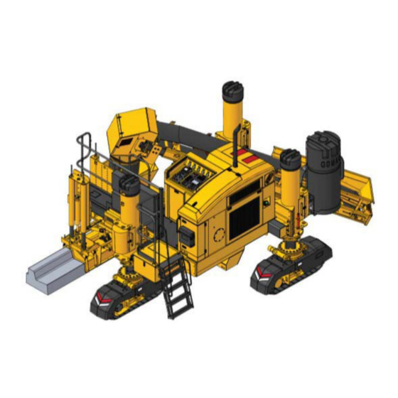
- Page 1 The Worldwide Leader in Concrete Paving Technology GT-3600 Trimmer/Paver Owner/Operator's Manual GOCRB software...
- Page 3 GT-3600 Trimmer/Paver Owner/Operator Manual MACHINE SERIAL NUMBER:__________________________ ENGINE SERIAL NUMBER:___________________________ GOMACO Corporation HIGHWAYS 59 & 175 Ida Grove, Iowa 51445 Telephone: 712-364-3347 Fax # (712) 364-3986 Form No. H-36G+1216 Version 0921 Printed in USA Copyright 2021 GOMACO...
- Page 4 Right hand and left hand sides are determined by facing the direction the GT-3600 will travel during paving operations. The two track end of the GT-3600 is referred to as the “front” and single track end is referred to as the “rear”.
- Page 5 GT-3600 G+ Table of Contents CHAPTER I ................................1-1 To the Customer ............................1-2 Table of Contents ............................1-3 Safety Section ............................1-8 Safety Decal Locations .........................1-12 Safety Decal Descriptions ........................1-23 Manual Revisions ..........................1-27 Chapter II Controls and Gauges ..........................2-1 Content of Chapter ..........................2-1 Control Console Cover ...........................2-1...
- Page 6 GT-3600 G+ Positioning the Legs ..........................3-15 Vertical Positioning ........................3-15 Lateral Positioning ........................3-16 Preparing and Mounting the Conveyor ....................3-18 Mounting the Slipform Mold .........................3-21 Hydraulic Connections ........................3-22 Mounting the Sensors (Standard) ......................3-24 Sensor Installation ........................3-26 Controller Setup ............................3-29 Left side grade control; Right side slope control .................3-29 Machine Setup #2 ........................3-29...
- Page 7 GT-3600 G+ Sensor Setup ..........................4-15 3D control ...........................4-16 Steer and Elevation Thresholds ....................4-17 Preliminary Adjustments ........................4-18 Mold Alignment to Machine Frame .....................4-18 Sensor Adjustments ........................4-19 Parallel Measurements and Adjustment ..................4-20 Final Adjustments..........................4-22 Pouring Operations ..........................4-25 Starting Pour From Header ......................4-25 Continuing the Pour from an Existing Wall .................4-26...
- Page 8 GT-3600 G+ Check conveyor belt tension and alignment ................5-12 Check wear on conveyor belt wipers ..................5-13 Check trimmer teeth cutting depth ....................5-13 Trimmerhead teeth replacement ....................5-15 Grease slew drives ........................5-15 250 hour or monthly service ........................5-16 Lubricate leg inner guide tubes ....................5-16 Grease the lower leg bearings (piston leg) .................5-16...
- Page 9 GT-3600 G+ Power Distribution Diagnostics ......................6-5 CAN Electrical Drawing .........................6-11 CAN Electrical Drawing .........................6-12 CAN Electrical Diagnostics ........................6-13 Machine CAN ..........................6-13 Active Faults ..........................6-13 Accessory CAN ..........................6-20 Emergency Stop Electrical Drawing ....................6-26 Emergency Stop Electrical Diagnostics ....................6-27 Lift and Steer Hydraulic Drawing (Servo) ....................6-31 Lift and Steer Hydraulic Drawing (CAN) ....................6-32...
- Page 10 You must replace a label if it is damaged, missing or cannot be read. If a label is on a part that is replaced, make sure a new label is installed on the replaced part. Contact your GOMACO dealer for new labels.
- Page 11 Safety Section Emergency Stop System Operating the machine with a defective emergency stop sytem can cause severe injury or death. Check the operation of each emergency stop button every day before beginning operation. Make certain that all emergency stop buttons are pulled out and that the check E-stop light on the panel is out. Depress each emergency stop button, one at a time.
- Page 12 Do not weld or flame cut the frame, pipes or tubes that contain flammable fluids without prior authorization and instruction from GOMACO or a GOMACO authorized dealer. Do not weld on the machine with the battery connected. Disconnect the battery negative (-) ground cable to prevent damage to the electrical system and /or explosion.
- Page 13 Make certain the lifting crane is suitable for the machine weight. GOMACO does not recommend transporting the machine completely assembled because of possible width, length and/or weight limitations. Be certain to have the proper permits and placarding when transporting the machine.
- Page 14 Safety Decal Locations Safety Decal Locations Decal Number Description 695-45F18 Pinch Point 695-45F20 Moving Track 695-45H98 Engine Shut Down 695-45R10 Do Not Lift 695-46K10 High Pressure Water 695-46K11 Do Not Run Pump 695-47T53 Diesel Fuel 695-47T55 Moving Frame 695-48F95 Pressure Washer 695-49K46 Oil Reservoir/Sump Filter Do Not Open 695-49M20...
- Page 15 Safety Decal Locations 1-13...
- Page 16 Safety Decal Locations 1-14...
- Page 17 Safety Decal Locations 1-15...
- Page 18 Safety Decal Locations 903151-047 1-16...
- Page 19 Safety Decal Locations 1-17...
- Page 20 Safety Decal Locations 1-18...
- Page 21 Safety Decal Locations 1-19...
- Page 22 Safety Decal Locations 1-20...
- Page 23 Safety Decal Locations 1-21...
- Page 24 Safety Decal Locations 1-22...
- Page 25 Safety Decal Descriptions Safety Decal Descriptions 695-45F21 WARNING! 695-45F18 Contact with moving cutter or auger can cause CAUTION! serious injury or death. Keep clear of cutter or auger while engine is Pinch point , keep clear while machine is in running.
- Page 26 Safety Decal Descriptions 695-47T55 WARNING! 695-47M98 WARNING! Moving frame and leg components. Getting caught in moving components can cause serious injury. Contact with moving auger will cause injury. Keep clear of area to avoid being caught in moving Keep grates and covers closed. components.
- Page 27 Safety Decal Descriptions 695-49M20 WARNING! The oil in this machine is combustible. 695-54N68 NOTICE DO NOT smoke within 50 feet of machine. DO NOT allow any hot or burning materials near. After stopping engine, wait until warning lamp goes off prior to disconnecting battery. Refer to manual for oil specifications.
- Page 28 Safety Decal Descriptions 695-55A83 WARNING! Moving frame and leg components. Getting caught in moving components can cause serious injury. Keep clear of area to avoid being caught in moving components. DCAL-109 NOTICE Switch to off position and remove key to prevent accidental start of machine during service.
- Page 29 Manual Revisions Manual Revisions 01/2021: Updated Safety Decal Location Drawings; Added Revision Record; CH2: Updated G+ controls for console cover, Auto track threshold setting; hyperlinked reference in all chapters; CH3: changed layout of trimmer assembly to cleanup cross model reuse; updated leg lateral position diagrams; added vertical adjusment of drawbar and hold down mounts;...
- Page 30 Manual Revisions 1-28...
Need help?
Do you have a question about the GT-3600 and is the answer not in the manual?
Questions and answers