
Related Manuals for Hioki 3286-20

Summary of Contents for Hioki 3286-20
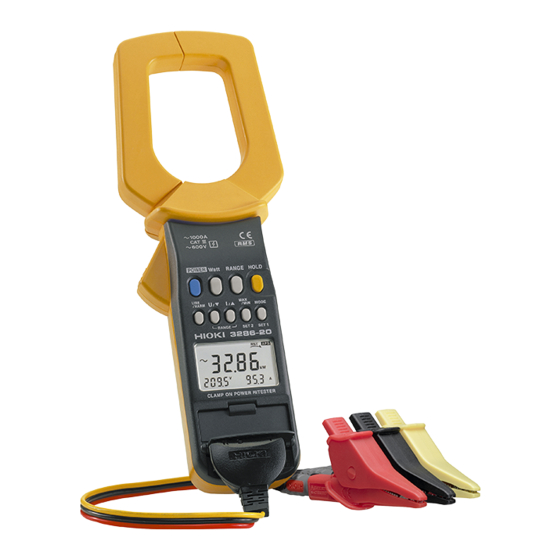
- Page 1 3286-20 Instruction Manual CLAMP ON POWER HiTESTER Apr. 2015 Revised edition 13 3286B981-13 15-04H...
-
Page 2: Table Of Contents
Contents Introduction Shipping Check Safety Note on Use Organization of This Manual xiii Chapter 1 Product Outline 1.1 Product Outline 1.2 Features 1.3 Parts and Functions 1.4 Flowchart of Key Operations 1.4.1 Current Measurements Mode 1.4.2 Harmonic Measurement 1.4.3 Change the Range Chapter 2 Measurement Procedure 2.1 Preparations... - Page 3 2.7 SLOW Mode 2.8 Recording Function 2.9 SETUP Function 2.10 Measurement Condition Save Function 36 2.11 Auto Power-Off Function 2.12 Battery Low Warning 2.13 Beep Tone Chapter 3 Specifications 3.1 Measurement Specifications 3.1.1 AC Current Measurement Specifications 3.1.2 AC Voltage Measurement Specifications 3.1.3 Specifications of Single-phase Power Measurement 1φ...
- Page 4 We have tried to bring this manual as close to perfection as we could achieve. If perchance you find any unclear portions, mistakes, omissions, or the like, we would be most obliged if you could please notify us of them via any HIOKI agent, or directly. Introduction...
-
Page 5: Shipping Check
If damage is evident, or if it fails to operate according to the specifications, contact your dealer or HIOKI representative. Check the 3286-20 Unit and the Supplied Accessories Main unit 3286-20 CLAMP ON POWER HiTESTER Supplied accessories... -
Page 6: Safety
Safety DANGER This instrument is designed to comply with IEC 61010 Safety Standards, and has been thoroughly tested for safety prior to shipment. However, mishandling during use could result in injury or death, as well as damage to the instrument. Be certain that you understand the instructions and precautions in the manual before use. - Page 7 Safety Symbols This manual contains information and warnings essential for safe operation of the instrument and for maintaining it in safe operating condition. Before using the instrument, be sure to carefully read the following safety notes. symbol printed on the instrument indicates that the user should refer to a corresponding topic in the manual (marked with the...
- Page 8 Symbols for various standards This symbol indicates that the product conforms to regulations set out by the EC Directive. Indicates the Waste Electrical and Electronic Equipment Directive (WEEE Directive) in EU member states. Measurement categories This instrument complies with CAT III safety requirements.
- Page 9 Using a measurement instrument in an environment designated with a higher-numbered category than that for which the instrument is rated could result in a severe accident, and must be carefully avoided. Use of a measurement instrument that is not CAT- rated in CAT II to CAT IV measurement applications could result in a severe accident, and must be carefully avoided.
-
Page 10: Note On Use
Using the product in such conditions could cause an electric shock, so contact your dealer or Hioki representative for replacements. (Model L9635- Note on Use... - Page 11 viii DANGER To avoid short circuits and potentially life- threatening hazards, never attach the clamp sensor to a circuit that operates at more than maximum rated voltage to earth. Clamp sensor should only be connected to the secondary side of a breaker, so the breaker can prevent an accident if a short circuit occurs.
- Page 12 WARNING Do not allow the instrument to get wet, and do not take measurements with wet hands. This may cause an electric shock. To avoid electric shock when measuring live lines, wear appropriate protective gear, such as insulated rubber gloves, boots and a safety helmet. To avoid electric shock when replacing the battery, first disconnect the voltage cord or clamp from the object to be measured.
- Page 13 CAUTION Avoid stepping on or pinching the cable, which could damage the cable insulation. Keep the cables well away from heat sources, as bare conductors could be exposed if the insulation melts. To prevent an electric shock accident, confirm that the white or red portion (insulation layer) inside the cable is not exposed.
- Page 14 CAUTION If the protective functions of the instrument are damaged, either remove it from service or mark it clearly so that others do not use it inadvertently. Do not store or use the instrument where it could be exposed to direct sunlight, high temperature or humidity, or condensation.
- Page 15 indicator appears when battery voltage NOTE becomes low. During which time accuracy cannot be guaranteed. Replace batteries only with the specified type. When replacing the battery, make sure that the metal battery snap fitting is firmly connected. If the metal fitting is loose, adjust it and recheck the connection.
-
Page 16: Organization Of This Manual
Organization of This Manual Chapter 1 Product Outline Explains the parts and functions of the instrument. Chapter 2 Measurement Procedure Explains how to use the 3286-20 for measurement. Chapter 3 Specifications Lists the specifications of the 3286-20 CLAMP ON AC/DC HiTESTER. Chapter 4... - Page 17 Organization of This Manual...
-
Page 18: Chapter 1 Product Outline
Chapter 1 Product Outline 1.1 Product Outline The "3286-20 CLAMP ON POWER HiTESTER" is designed to provide multiple functions by adopting a single-chip microcomputer. At any desired point of a single-phase circuit or three-phase circuit, this instrument enables the measurement of voltage,... -
Page 19: Features
1.2 Features A multi-function microcomputer The built-in microcomputer offers various functions in a compact form. Display of true rms values The true rms value conversion circuit allows accurate measurement of currents with distorted waveforms. Enables power measurement When both current and voltage are input simultaneously, the power factor, phase angle, reactive factor, as well as power can be measured, and phase detected. -
Page 20: Parts And Functions
1.3 Parts and Functions Top and Side View Chapter 1 Product Outline... - Page 21 POWER Used to turn power on/off Watt Used to select the display of active power, apparent power, or power factor for the 1φ P meter. Used to select the display of power factor, phase difference, or reactive factor for the 1φ PF meter. Used to select the display of active power, apparent power, power factor, phase difference, or reactive factor for the 3φ...
- Page 22 (RANGE) key Selects voltage display mode. Pressing this key in voltage display mode resets the peak-hold value. Switches MAX/MIN display of effective value and peak value during REC. Enables the setting of a voltage range in range setup mode. Lowers the order in harmonic display mode. (RANGE) key Selects current display mode.
- Page 23 10. Clamp sensor To measure current, open the top ends of the clamp sensor by gripping the lever 11. Then position the conductor to be measured at the center of the clamp sensor and firmly close the clamp sensor. 11. Lever Used to open and close the clamp sensor.
- Page 24 17. Display (LCD) Display 1 Display 2 Display 3 Alternating Current (AC) cosφ Power factor sinφ Reactive factor Data hold function HOLD Data output DATA Three-Phase Reverse phase Normal phase Missing phase Auto power off function Slow Record function LEAD Lead phase Lag phase Battery low warning...
- Page 25 Active power Apparent power Voltage Maximum value Minimum value Harmonic percentage %THD Total harmonic distortion ratio Frequency var (reactive power) Total harmonic distortion ratio-F (A distortion rate against the basic wave.) Total harmonic distortion ratio-R (A distortion rate toward the actual effective value.) The Data Output function is only available for customers who have the Model 9636 RS-232C Cable, Model 9636-01...
-
Page 26: Flowchart Of Key Operations
1.4 Flowchart of Key Operations 1.4.1 Current Measurements Mode A point of view: This shows the way of changing on Display 1 to 3. Display 1 Display 2, Display 3 1φ P LINE/HARM key 3φ 1φ 1φ HARM I HARM U 1φ... - Page 27 REC ON Watt key MAX, MIN MAX, MIN (Return to the power Ipeak indication with MAX, MIN MAX, MIN the Watt key) (Return to the power Upeak MAX, MIN MAX, MIN indication with the Watt key) MODE key Remaining MAX/MIN Elapsed time battery display...
-
Page 28: Harmonic Measurement
1.4.2 Harmonic Measurement 1φ P LINE/HARM key 3φ 1φ 1φ HARM I HARM U 1φ PF MODE key THD-R THD-F Content 1st order 2nd-order - - - - 20th order 20th order 19th-order - - - - 1st order 1.4.3 Change the Range RANGE key Measurement RANGE... - Page 29 Chapter 1 Product Outline...
-
Page 30: Chapter 2 Measurement Procedure
Chapter 2 Measurement Procedure 2.1 Preparations 1. Remove the back case and insert a battery. (Refer to "Chapter 4 Battery Replacement".) 2. Press to turn the instrument on. Verify that POWER all segments of the display light up briefly. The model name then appears on Display 1 and battery state on Display 3. -
Page 31: Connections
[To initialize the saved contents] Holding down the key when powering on RANGE initializes all the saved contents. (SETUP Function, measurement condition save Function) 2.2 Connections Before conducting measurement, check the connections. WARNING Due to the risk of electric shock, connect the yellow cord not used for measurement to the part to which the black cord connects to prevent the clip from accidentally touching... - Page 32 [Single-Phase Two-Wire Circuit] Yellow Black Figure 1. Power Measurement on Single-Phase Two-Wire Circuit Chapter 2 Measurement Procedure...
- Page 33 [Single-Phase Three-Wire Circuit] The power and power factor of a single-phase three- wire circuit are measured similar to measurement on a single-phase two-wire circuit. Connect the black cord to the neutral wire as shown in Figure 2, then switch the red cord and clamp sensor to the respective wires.
- Page 34 [Three-Phase Three-Wire Circuit] Use another method of the power measurement of the figure 4 for the distortion wave. Black Yellow Figure 3. Power and power factor measurement on Three-Phase Three-Wire Circuit 1φP, P Yellow Black Yellow Black 1φP, P Three-phase effective power P=P Figure 4.
- Page 35 [Three-Phase Four-Wire Circuit] The power and power factor of a three-phase four- wire circuit are measured similar to measurement on a three-phase three-wire circuit (provided the load is balanced). No neutral wire is used for this measurement, however. In case of unbalanced load, measurement is conducted similar to measurement on a single-phase two-wire circuit.
- Page 36 [Current measurement] Figure 6. Current measurement When only measuring current, the orientation of the clamp sensor is irrelevant. Moreover, the voltage cord need not be connected to the instrument. [Voltage measurement] Yellow Black Figure 7. Voltage measurement When only measuring voltage, the clamp sensor need not be clamped.
-
Page 37: Range Setup
2.3 Range Setup 1. Press the key. The voltage range then RANGE appears on Display 2 and current range on Display 3. In this condition, Display 2 and Display 3 should be blinking. 2. To change the voltage range, press the key. -
Page 38: Power Measurement
Table 2. Range Composition for Three-Phase Power Measurement Voltage range 150.0V 300.0V 600V 6.000k 20.00A 6.000k 24.00k 12.00k Current 60.00k 200.0A 60.00k 240.0k range 120.0k 600.0k 1000A 300.0k 600.0k 1200k Unit [W] or [VA] or [var] 3. After changing the range, press the key. -
Page 39: P Meter, 1Φ Pf Meter And 3Φ Pf Meter
2.4.1 1φ P Meter, 1φ PF Meter and 3φ PF Meter [1φ P Meter] Displays active power P once about every second (once about every three seconds in SLOW mode). The meter calculates apparent power S, reactive power Q, and power factor COS φ from active power P, voltage U, and current I. - Page 40 [Difference in λ between 1φ P Meter and 1φ PF Meter] For distorted waveforms, the value of power factor λ may differ between the 1φ P meter and 1φ PF meter. The difference is due to the fact that the 1φ P meter calculates λ...
- Page 41 1φP, P 1 (R) Yellow Black Yellow Black 1φP, P Three-phase effective power P=P Measurement example P (1φ P) S (1φ P) -0.54 kW 2.61 kVA 1.98 kW 2.57 kVA Three-phase effective power P=P1+P2=-0.54+1.98=1.44 kW Three-phase apparent power S=( )/2 (2.61+2.57)=4.49 kVA Power factor λ=P/S=1.44/4.49=0.321 Chapter 2...
-
Page 42: Power And Power Factor
Table 3. Items Displayed (Marked OK) and Not Displayed (-) 1φ P 1φ PF 3φ PF Current I Voltage U Effective power P Apparent power S Reactive power Q Power factor λ (COSφ) Phase angle φ Reactive factor SINφ 2.4.2 Power and Power Factor WARNING Due to the risk of electric shock, connect the yellow cord not used for measurement to the... - Page 43 2. Connect the voltage cord to the instrument, then connect the red cord, black cord, and yellow cord to the circuit under measurement according to prescribed connections. For a three-phase circuit, the instrument will display the results of phase detection as follows: Normal phase Reverse phase Missing phase...
-
Page 44: Phase Detection
5. Pressing the key in active power or MODE apparent power display mode indicates reactive power. Pressing the key again restores the MODE current and voltage display. U, I vAr, Q U, I vAr, Q 6. Switch between Auto Range and Manual Range, as needed. -
Page 45: Current (Frequency)
2.4.4 Current (Frequency) 1. Press the key to activate current display mode. In current display mode, the instrument will indicate an effective value on Display 1, peak hold value on Display 2, and frequency on Display 3. 2. Switch between Auto Range and Manual Range, as needed. -
Page 46: Voltage (Frequency)
Automatic frequency detection (AUTO), 50 Hz fixed, or NOTE 60 Hz fixed can be selected. In cases where the input fluctuates significantly, the indicated value will stabilize when 50 Hz or 60 Hz fixed is selected. For how to select, see the setup of measurement line frequency in SETUP mode. -
Page 47: Harmonic Measurement
For measurement extending the auto power-off time, NOTE use the recording function. To check variations in a peak value, enable the REC function by pressing the key, then MAX/MIN activate peak value display mode by pressing the key. Automatic frequency detection (AUTO), 50 Hz fixed, or 60 Hz fixed can be selected. - Page 48 1st order 2nd order - - - - 20th order 20th order 19th order - - - - 1st order 5. Switch between the total harmonic distortion ratio (THD-R, THD-F) and harmonic percentage from one to another, as needed, by pressing the key.
-
Page 49: Voltage Harmonics
2.5.2 Voltage Harmonics 1. Press the key to activate harmonic LINE/HARM voltage display mode. 1φ P 3φ 1φ 1φ HARM I HARM U 1φ PF 2. Connect the voltage cord to the instrument, then connect the red cord and black cord to the circuit under measurement. -
Page 50: Data Hold Function Hold
2.6 Data Hold Function HOLD This function freezes the counter at any desired point for easy reading. Press the key. annunciator lights on HOLD HOLD the display and the digital display value is maintained. The data hold function is available for all measurements. - Page 51 3. Pressing the key while using the recording MODE function lets you check the elapsed time and remaining battery capacity. Remaining MAX/MIN Elapsed time battery display display capacity display In elapsed time display, the instrument indicates hours on Display 2 and minutes on Display 3. When elapsed time is displayed with MAX or MIN blinking, a negative value is denoted.
-
Page 52: Setup Function
2.9 SETUP Function The settings for this instrument are made in SETUP mode. In SETUP mode, you can make settings for measurements, display, and ancillary functions. 1. Hold down the key while powering on the SET1 instrument by pressing the key. -
Page 53: Measurement Condition Save Function
(2) Setup of measurement line frequency Item No. 1-02 AUTO Automatically detects measurement line frequency. 50 Hz Sets measurement line frequency to 50 Hz. 60 Hz Sets measurement line frequency to 60 Hz. (3) Setup of display update rate Item No. 1-03 (SAMP) NORM Sets display update to normal rate (1 s). -
Page 54: Auto Power-Off Function Aps
3. To return the saved measurement conditions to their initial values, hold down the key at HOLD instrument power-on. After the entire LCD goes on, the instrument will display " ", and the saved contents of measurement conditions are returned to their initial values. 2.11 Auto Power-Off Function When annunciator is displayed, the auto power-... - Page 55 Chapter 2 Measurement Procedure...
-
Page 56: Chapter 3 Specifications
Chapter 3 Specifications 3.1 Measurement Specifications Temperature and 5 (73 9 ), 80% RH or less humidity for (no condensation), battery warning guaranteed accuracy indicator is off. Guaranteed accuracy 1 year, or opening and closing of the period Clamp Sensor 10000 times, whichever comes first 3.1.1 AC Current Measurement Specifications Maximum permissible... -
Page 57: Ac Voltage Measurement Specifications
AC current (wave peak value) I PEAK Accuracy Range Resolution (Accuracy Range) 45Hz to 1kHz 20.0 A 0.1 A 3.0%rdg. 5dgt. (1.0 A rms to 20.0 A rms) 200 A 3.0%rdg. 5dgt. (10.0 A rms to 200.0 A rms) 1000 A 3.0%rdg. -
Page 58: Specifications Of Single-Phase Power Measurement 1Φ P Meter
3.1.3 Specifications of Single-phase Power Measurement 1φ P Meter Measurement Single phase, 50/60 Hz condition Measurement range Effective measurement current range: 1 A to 1000 A Effective measurement voltage range: 80 V to 600 V Out of range If either the current (line current) range or voltage (line voltage) range is out of range, power measurement will also be out of range. -
Page 59: Specifications Of Power Factor And Phase Angle Measurements 1Φ Pf Meter And 3Φ Pf Meter
3.1.4 Specifications of Power Factor and Phase Angle Measurements 1φ PF Meter and 3φ PF Meter Measurement Singe phase/balanced three phases, conditions 50/60 Hz, sine wave Measurement range Effective measurement current range: 1 A to 1000 A Effective measurement voltage range: 80 V to 600 V Phase angle measurement φ... -
Page 60: Specifications Of Balanced Three-Phase Power Measurements
3.1.5 Specifications of Balanced Three-phase Power Measurements Active and apparent power measurements Measurement Balanced three phases, 50/60 Hz, sine conditions wave Method of Active power calculated from apparent measurement power and phase angle information. Measurement range (Active power P/Apparent power S) Current Current (line current) Range Voltage... -
Page 61: Specifications Of Frequency Measurement
3.1.6 Specifications of Frequency Measurement Measurement ranges (For current measurement/voltage measurement) Range Resolution Accuracy (Accuracy Range) 100.0 Hz 0.1 Hz 0.3%rdg. 1dgt. (30.0 Hz to 100.0 Hz) 1000 Hz 1 Hz 1.0%rdg. 1dgt. (100 Hz to 1000 Hz) Minimum input Current: 1.00 A rms, Voltage: 10.0 V rms 3.1.7 Specifications of Harmonic Measurement Measurement... -
Page 62: General Specifications
Measurement accuracy Harmonic levels Order Accuracy 3.0%rdg. 10dgt. 2 to 6 3.5%rdg. 10dgt. 7 to 8 4.5%rdg. 10dgt. 9 to 10 5.0%rdg. 10dgt. 11 to 15 7.0%rdg. 10dgt. 16 to 20 10%rdg. 10dgt. Harmonic 1 dgt. with respect to calculation from percentage each measured value. - Page 63 Auto power-off Automatic shutdown after 10.5 minutes. Beep tone warning before the shutdown. Extending and disabling possible. Battery low voltage When the battery voltage falls below a power-off certain level, the function shuts down the instrument to prevent malfunctions. Beep tone ON/OFF ...
- Page 64 Zero suppression 5 counts (for current and voltage measurement) Location for use Indoor, altitude up to 2000 m (6562 feet) Applicable standards Safety: EN 61010 Measurement categories III (expected transient overvoltage: 6000 V), Pollution level 2, EN 60529 IP40 (protected against access to hazardous parts with a wire) EMC: EN 61326...
- Page 65 Accessories 9245 CARRYING CASE L9635-01 VOLTAGE CORD Hand Strap Battery Instruction manual Chapter 3 Specifications...
-
Page 66: Operation Expressions
3.3 Operation Expressions General operation expressions Operation Function Item Symbol Expression Current Current measurement (Effective [Arms] value) Voltage Voltage measurement (Effective [Vrms] value) Single-phase power 1φ active measurement power 1φ P meter 1φ apparent power [VA] 1φ reactive power [var] λ... - Page 67 Operation Function Item Symbol Expression λ(3φ) Balanced three- 3φ power For line current I phase power factor, factor lags U phase angle, and cos |φ-30 | power For line current I measurements 3φ PF leads U meter cos (|φ|+30 ) (Balanced three 3φ...
- Page 68 Harmonic operation expressions Operation Item Symbol Expression Harmonic Effective value current [Arms] k-th harmonic content Overall harmonic THD-F distortion factor THD-R Harmonic Effective value voltage [Vrms] k-th harmonic content Overall harmonic THD-F distortion factor THD-R Remarks: Harmonic order Chapter 3 Specifications...
- Page 69 Chapter 3 Specifications...
-
Page 70: Chapter 4 Battery Replacement
Chapter 4 Battery Replacement WARNING To avoid electric shock when replacing the battery, first disconnect the voltage cord or clamp from the object to be measured. After replacing the battery, replace the cover and screws before using the instrument. When replacing the battery, be sure to insert them with the correct polarity. - Page 71 indicator appears when battery voltage NOTE becomes low. During which time accuracy cannot be guaranteed. Replace batteries only with the specified type. When replacing the battery, make sure that the metal battery snap fitting is firmly connected. If the metal fitting is loose, adjust it and recheck the connection.
-
Page 72: Chapter 5 Attaching The Hand Strap
Chapter 5 Attaching The Hand Strap Explains how to attach the hand strap, for easy handling of the instrument in the field. Chapter 5 Attaching The Hand Strap... - Page 73 Chapter 5 Attaching The Hand Strap...
-
Page 74: Chapter 6 Storage In Carrying Case
Chapter 6 Storage in Carrying Case Store all instruments in the carrying case, then secure it with the band. Chapter 6 Storage in Carrying Case... - Page 75 Chapter 6 Storage in Carrying Case...
-
Page 76: Chapter 7 Troubleshooting
Chapter 7 Troubleshooting If the instrument seems not to be working normally, check the following points first before requesting service. Symptom Battery Battery clip Voltage cord Instrument does not come on. indication appears and instrument immediately turns off. indication appears. Instrument turns off during use.* Voltage cannot be... - Page 77 Symptom Confirmation item. and etc. Cannot be measured. (1φ PF meter, 3φ PF meter) "- - - -" will be Confirm the direction of the clamp sensor, and displayed. connections of the voltage cord. Becomes fixed. (Frequency measurement) Check the waveform. Some special frequencies can't be measured, such as those of inverters.
-
Page 78: Service
The minimum stocking period for replacement parts is five years after end of production. If damage is suspected, check the "Troubleshooting" section before contacting your dealer or HIOKI representative. For information regarding service, please contact your dealer or the nearest HIOKI representative.
Need help?
Do you have a question about the 3286-20 and is the answer not in the manual?
Questions and answers