
Related Manuals for 4-Max Inspiration F3A 50E


Summary of Contents for 4-Max Inspiration F3A 50E
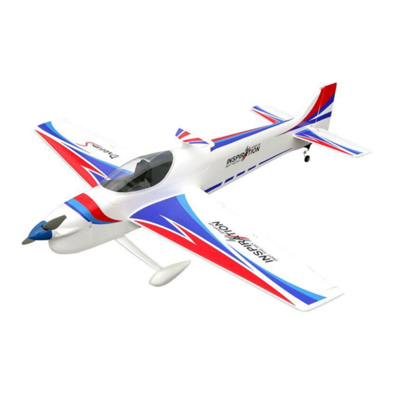
- Page 1 4-Max Inspiration F3A, 50e Assembly Instructions Specifications Class Type Material EPO Foam Wingspan 1380mm / 54.33” Length 1480mm / 58.26” Flying Weight 1950g / 4.3lbs (inc 4S 3700mAh battery) www.4-Max.co.uk...
-
Page 2: Required Items
This model should be built and flown by an experienced builder and R/C Flyer. 4-Max Models guarantees this model to be free of defects at the date of purchase. This warranty does not cover any parts damaged by use, modification or crash damage. - Page 3 4-Max Models Max Models Max Models immediately. immediately. Airframe Parts...
- Page 4 Insert into the pre-cut slot/holes in the rudder. Make sure the tail wheel wire is also inserted in the rudder when gluing the rudder on. Ensure no glue is on the centre part of the pin hinges www.4-Max.co.uk Sales@4-Max.co.uk Tel: 01256 782 512...
- Page 5 Attach the motor to the “X” mount (supplied) Step 12 Install the motor assembly on the motor box using the 10mm spacers (supplied). Step 13 Install the Prop driver on the motor using the 4 screws supplied with the motor. www.4-Max.co.uk Sales@4-Max.co.uk Tel: 01256 782 512...
- Page 6 The wheels should rotate freely, but not be loose, adjust if necessary. Step 18 Install the spats to the undercarriage leg using the two M2.5 by 10mm long screws as per the photo. www.4-Max.co.uk Sales@4-Max.co.uk Tel: 01256 782 512...
- Page 7 Attach the servo extension lead to the servo and either glue or tape in place so they are flush to the bottom surface of the wing. www.4-Max.co.uk Sales@4-Max.co.uk Tel: 01256 782 512...
- Page 8 Tip: Add a bit of tape to one end of the ply plates to allow you to remove them once installed. Step 25 Install the propeller and cooling Spinner to the motor. Make sure the propeller spins freely and doesn’t touch the plastic nose cone www.4-Max.co.uk Sales@4-Max.co.uk Tel: 01256 782 512...
- Page 9 Rudder: +45mm, -45mm, 30% Exponential Don’t forget to range test your model as per the radio manufacturer’s instructions. We hope you have enjoyed assembling this model and may your take off’s equal your landings. www.4-Max.co.uk Sales@4-Max.co.uk Tel: 01256 782 512...
Need help?
Do you have a question about the Inspiration F3A 50E and is the answer not in the manual?
Questions and answers