Advertisement
Quick Links
Advertisement

Summary of Contents for MONSTER FITNESS AF1001
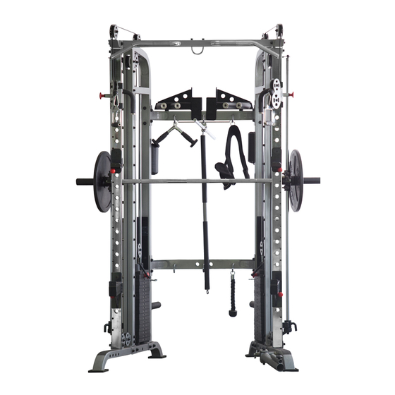
- Page 1 Monster Fitness Commercial Functional System AF1001 ASSEMBLY INSTRUCTIONS...
- Page 2 EXPLODED DIAGRAM 1...
-
Page 3: Exploded Diagram
EXPLODED DIAGRAM 2... - Page 4 PARTS LISTING AND HARDWARE SPEC KEY NO. PART DESCRIPTION MON-G6 Q'TY LEFT MAIN UPRIGHT RIGHT MAIN UPRIGHT LEFT SLIDE FRAME RIGHT SLIDE FRAME GUIDE ROD SIDE SHELL LEFT BASE RIGHT BASE BOTTOM CROSS FRAME MIDDLE CROSS FRAME TOP CROSS FRAME PULL BAR LEFT CHIN UP BAR RIGHT CHIN UP BAR...
- Page 5 SHEATHING ROUND PLUG GUIDE SLEEVE RUBBER PAD WASHER 10MM WASHER 12MM LOCK NUT NYLOCK NUT HEXAGONAL HEAD SCREW M10*20 SOCKET CAP SCREW M10*50 SOCKET CAP SCREW M10*70 SOCKET CAP SCREW M10*90 SOCKET CAP SCREW M10*105 SOCKET CAP SCREW M12*25 SOCKET CAP SCREW M12*75 SOCKET CAP SCREW M12*95...
- Page 6 RIGHT BARBELL SUPPORT BAR SUPPORT HOLDER PLATE BAR NYLON PLATE-1 NYLON PLATE-2 NYLON PLATE-3 NYLON PLATE-4 NYLON PLATE-5 NYLON PLATE-6 FOAM ROLLER M5*10 SOCKET HEAD SCREW HEXAGONAL HEAD SCREW M12*25 CIRCLE HOOK FOAM COVER BAR SUPPORT ROTATION SUPPORT AXIS COPPER BUSHING SMALL COPPER BUSHING LOCK PIN PLUM SHAPED SCREW...
-
Page 9: Assembly Diagram
ASSEMBLY DIAGRAM 1 USE A PARTNER TO HELP WITH THIS STEP REMEMBER: Only hand tighten all nuts and bolts until whole machine is assembled 1. Attach a RUBBER PAD (44) to each foot on the LEFT BASE (7) (Skip this step if pre-assembled) 2.... - Page 10 ASSEMBLY DIAGRAM 2 USE A PARTNER TO HELP WITH THIS STEP REMEMBER: Only hand tighten all nuts and bolts until whole machine is assembled 1. Attach a RUBBER PAD (44) to each foot on the RIGHT BASE (8) (Skip this step if pre-assembled) 2....
- Page 11 M10X105 (54), two WASHER 10MM (45) and LOCK NUT M10 (47) 5. Ensuring correct orientation, slide the assembled RIGHT SLIDER (16) onto the RIGHT SLIDE FRAME (4), secure with SLIDER PIN (32) 6. Position the RIGHT SLIDE FRAME (4) between RIGHT BASE (8) and the RIGHT MAIN UPRIGHT (2). Attach each end using two SCREWS M12X95 (58), four WASHER 12MM (46) and two NYLOCK NUTS M12 (49) 7 ....
- Page 12 ASSEMBLY DIAGRAM 3 USE A PARTNER TO HELP WITH THIS STEP REMEMBER: Only hand tighten all nuts and bolts until whole machine is assembled 1. Attach the BOTTOM CROSS FRAME (9) and the REINFORCEMENT PALTE (63) to the rear of the LEFT &...
- Page 13 ASSEMBLY DIAGRAM 4 USE A PARTNER TO HELP WITH THIS STEP REMEMBER: Only hand tighten all nuts and bolts until whole machine is assembled 1. Insert the ends without an attached nut of two GUIDE RODS (5), into the holes on the LEFT BASE (7) 2.
- Page 14 ASSEMBLY DIAGRAM 5 USE A PARTNER TO HELP WITH THIS STEP REMEMBER: Only hand tighten all nuts and bolts until whole machine is assembled 1. Insert a SCREW M10X90 (53) through a WASHER 10MM (45) into the top hole in the RIGHT MAIN UPRIGHT (2) 2.
- Page 16 ASSEMBLY DIAGRAM 6 USE A PARTNER TO HELP WITH THIS STEP REMEMBER: Only hand tighten all nuts and bolts until whole machine is assembled Bring the threaded end of a CABLE (30) from A→B→C→D→E→F→G→H→15. Repeat the steps to route the cable through the opposite side. Assemble the PULL BAR (12) by attaching two LONG FOAM ROLLERS (40), using two LOCK NUTS M8 (60), two BEARINGS (35), two CIRCLE FOR HOLES (36) and two CIRCLE HOOKS (26) (See the exploded diagram for more detail, skip this step if pre-assembled)
- Page 17 ASSEMBLY DIAGRAM 7 USE A PARTNER TO HELP WITH THIS STEP REMEMBER: Only hand tighten all nuts and bolts until whole machine is assembled Attach the HOLD SUPPORTS (81&82) to the front of the SLIDE FRAMES (3&4) using two PINS (95) Insert a HOLDER (86) through a frontal hole on the LEFT HOLD SUPPORT (81).
Need help?
Do you have a question about the AF1001 and is the answer not in the manual?
Questions and answers