Table of Contents
Advertisement
Quick Links
Advertisement
Table of Contents

Related Manuals for qualiton P200


Summary of Contents for qualiton P200
- Page 1 Qualiton P200 User’ s Manual...
-
Page 3: Table Of Contents
CONTENTS IMPORTANT SAFETY INSTRUCTIONS........ 4 AC MAINS CONNECTION ............34 MARKINGS ................8 DESCRIPTION OF THE P200’s BIAS SYSTEM ....35 PREFACE ................... 9 REPLACEMENT OF FUSE ............36 BASIC INFORMATIONS ............10 WASTE MANAGEMENT ............37 ...11 TECHNICAL ASSISTANCE AND SERVICE INFORMATION STEREO MODE SPECIFICATIONS ........12 BRIDGE MODE SPECIFICATIONS........13... -
Page 4: Important Safety Instructions
QUALITON P200 IMPORTANT SAFETY INSTRUCTIONS PLEASE READ THEM BEFORE OPERATING THIS EQUIPMENT. 1. Read these instructions. 9. Do not install near any heat sources such as radiators, heat registers, stoves, or other apparatus 2. Keep these instructions. (including amplifiers) that produce heat. - Page 5 QUALITON P200 IMPORTANT SAFETY INSTRUCTIONS PLEASE READ THEM BEFORE OPERATING THIS EQUIPMENT. them across sharp surfaces, do not clam them apparatus. When a cart is used, use caution when together and do not leave them in a hanging moving the cart/apparatus combination to avoid position.
- Page 6 QUALITON P200 IMPORTANT SAFETY INSTRUCTIONS PLEASE READ THEM BEFORE OPERATING THIS EQUIPMENT. the apparatus has been exposed to rain or moisture, extinguish the fire, even if the amplifier is switched does not operate normally, or has been dropped. off. 20. You must not start up damaged or faulty 25.
- Page 7 QUALITON P200 IMPORTANT SAFETY INSTRUCTIONS PLEASE READ THEM BEFORE OPERATING THIS EQUIPMENT. 30. The mains plug of the power supply cord shall remain readily operable. 31. Do not expose batteries to excessive heat such as sunshine, fire or the like.
-
Page 8: Markings
QUALITON P200 MARKINGS The exclamation point within an equilateral The product meets the relevant directives triangle is intended to alert the user to the and standards of the European Union. presence of important operating and maintenance (servicing) instructions in the literature accompan‐... -
Page 9: Preface
QUALITON P200 PREFACE Before installing the Qualiton P200 stereo vacuum tube power amplifier, please study this user manual carefully. Operating your power amplifier in a manner it is designed for, ensures you an utmost musical experience and a reliable operation. -
Page 10: Basic Informations
QUALITON P200 BASIC INFORMATIONS For your convenience, please fill out the following lines to facilitate any future technical assistance and repair service: Serial Number: _______________________________ Date of purchase: _______________________________ Dealer Name: _______________________________... -
Page 11: Technical Assistance And Service Information
If at any time you have any questions about your Qualiton product, do not hesitate to contact your local Qualiton dealer, who is at your disposal. If you or your dealer need more help, you can receive technical assistance at: Audio-Hungary Ltd. -
Page 12: Stereo Mode Specifications
QUALITON P200 STEREO MODE SPECIFICATIONS Rated output power 2 x 100 W Input impedance, Balanced Stereo IN 40 kOhm Input impedance, Unbalanced Stereo IN 10 kOhm Input sensitivity, Balanced Stereo IN 480 mV, to rated output Input sensitivity, Unbalanced Stereo IN... -
Page 13: Bridge Mode Specifications
QUALITON P200 BRIDGE MODE SPECIFICATIONS Rated output power 1 x 200 W Input impedance, Bridge IN 20 kOhm Input sensitivity, Bridge IN 1V, to rated output Gain +32 dB (RL = 8 Ohm) Frequency response 20 Hz to 55 kHz (-3 dB, rated output) Total Harmonic Distortion <... -
Page 14: General Specifications
QUALITON P200 GENERAL SPECIFICATIONS Number of input ports / channel 1 unbalanced Stereo IN 1 balanced Stereo IN 1 balanced Bridge IN Number of output ports / channel 1 unbalanced Power OUT Tubes required 4 x KT120 (KT150 or KT170 optionally) -
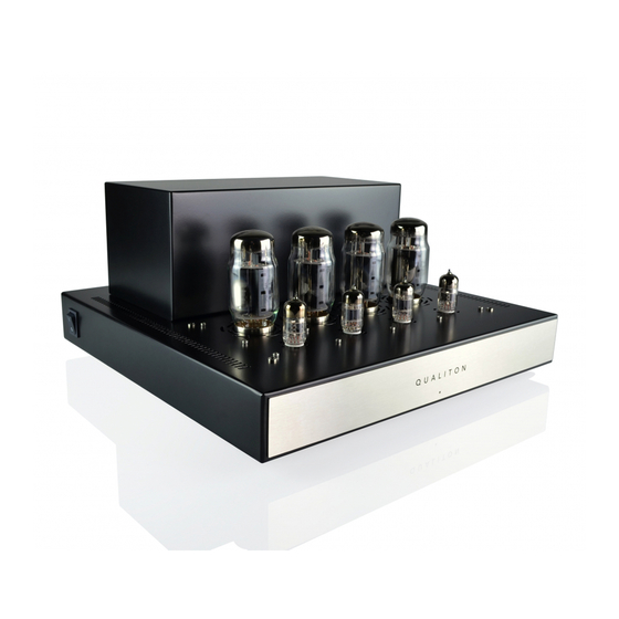
Page 15: Front Panel
QUALITON P200 FRONT PANEL 1. POWER ON indicator LED. -
Page 16: Rear Panel
QUALITON P200 REAR PANEL... - Page 17 2. BALANCED STEREO INPUT accepts high level, stereo program source signal. 8. IEC Appliance AC INLET with built-in main fuse holder to connect the Qualiton P200 to a live AC 3. STEREO INPUT / BRIDGE INPUT selector switch. outlet. 4. BALANCED BRIDGE INPUT accepts high level, 9.
-
Page 18: Unpacking
QUALITON P200 UNPACKING... - Page 19 QUALITON P200 UNPACKING PLASTIC BAG...
- Page 20 QUALITON P200 UNPACKING FABRIC BAG FABRIC BAG PLASTIC BAG...
-
Page 21: Contents Of Package
Once you have unpacked the entire contents of the package, you can now check that you have received all the accessories. • 1 pc Qualiton P200 power amplifier • 1 pc User’s Manual • 4 pcs KT120 / KT150 power tubes •... -
Page 22: Placement
QUALITON P200 PLACEMENT • Please read the following carefully to select a • The aforesaid applies to the very first installation of proper location for your amplifier. the appliance as well. Prior to the first installation, leave the amplifier at its place of operation at least •... -
Page 23: Installation Of Vacuum Tubes
QUALITON P200 INSTALLATION OF VACUUM TUBES • You have to remove the protective cover to prepare 12AX7 and carefully place it in one of the positions for the insertion of the electron tubes. Because the labeled 12AX7 / ECC83 on the amplifier. Make sure... - Page 24 QUALITON P200 INSTALLATION OF VACUUM TUBES V1: KT120 / KT150 V2: KT120 / KT150 V3: KT120 / KT150 V4: KT120 / KT150 6922 / E88CC 12AX7 / ECC83 12AX7 / ECC83 6922 / E88CC...
- Page 25 QUALITON P200 INSTALLATION OF VACUUM TUBES KT120 / KT150 6922 / E88CC...
-
Page 26: Using Third Party Vacuum Tubes
QUALITON P200 USING THIRD PARTY VACUUM TUBES • Audio-Hungary Ltd. does not recommend the use of any other electron tubes in the P200 power amplifier other than those supplied with the device. • Audio-Hungary Ltd. cannot and does not warrant... -
Page 27: Operating Modes Of The P200
DIAGRAMS. You can then use the STEREO INPUT / BRIDGE INPUT selector switch to select the input source for the chosen operation mode. • In order to properly configure the P200 within your sound system according to your needs, please now carefully study this section and the AMPLIFIER... -
Page 28: Stereo Mode Operation
QUALITON P200 STEREO MODE OPERATION • In STEREO mode the P200 can be used as a conventional stereo power amplifier to which you can connect an UNBALANCED or BALANCED stereo input signal. These two STEREO inputs cannot be used at the same time. In case a signal source is... -
Page 29: Bridge Mode Operation
QUALITON P200 BRIDGE MODE OPERATION • In BRIDGE mode the P200 can be used as a monoblock power amplifier with a BALANCED input. In this mode, the two channels of the stereo amplifier are fed from a monaural, symmetrical audio signal (BRIDGE input), and a single 8 Ohm loudspeaker can be connected between the two amplifier outputs, bridging the output terminals. -
Page 30: Amplifier Block Diagram
QUALITON P200 AMPLIFIER BLOCK DIAGRAM... -
Page 31: Connection Diagram - Stereo Mode
QUALITON P200 CONNECTION DIAGRAM - STEREO MODE P200 POWER AMPLIFIER * If a signal source is connected to the BALANCED stereo input, UNBALANCED - OR - BALANCED* the UNBALANCED stereo input is ignored. FROM EXTERNAL FROM EXTERNAL PREAMPLIFIER PREAMPLIFIER (OPTIONAL) -
Page 32: Connection Diagram - Bridge Mode
QUALITON P200 CONNECTION DIAGRAM - BRIDGE MODE P200 POWER AMPLIFIER P200 POWER AMPLIFIER RIGHT OUTPUTS LEFT FROM EXTERNAL PREAMPLIFIER (OPTIONAL) -
Page 33: Loudspeaker Connections
LOUDSPEAKER CONNECTIONS • Depending on the operating mode you wish to use (STEREO or BRIDGE), connect your speakers to the P200's outputs according to the corresponding CONNECTION DIAGRAM. • Do not turn on the amplifier until proper loads are connected to their respective output terminals (4 or 8 Ω, marked on the amplifier). -
Page 34: Ac Mains Connection
~ 115 V/60 Hz at 10.0 Amps ~ 230 V/50 Hz at 6.3 Amps • Make sure you want to operate the P200 at the AC mains voltage and frequency marked on the back. • The standard IEC power inlet with fuse holder are placed on the rear panel. -
Page 35: Description Of The P200'S Bias System
QUALITON P200 DESCRIPTION OF THE P200’� BIAS SYSTEM • P200 features sophisticated, microprocessor-based, fully automatic bias control system for the four power tubes. This circuit continuously monitors the behavior of each tube and regulates the bias voltages accordingly. • The above means that no further adjustment is required once the electron tubes supplied with the unit have been installed. -
Page 36: Replacement Of Fuse
QUALITON P200 REPLACEMENT OF FUSE The IEC power inlet features a built‑in fuse holder. The specification of replacement fuses are: T 6.3 L for 230 V AC mains and T 10.0 L for 115 V AC mains. 1. Open the fuse holder with a screwdriver. -
Page 37: Waste Management
QUALITON P200 WASTE MANAGEMENT • The appliance and its packaging are made of recyclable materials. • The appliance contains repairable or recyclable components and materials. Waste separation makes their recycling possible. • A faulty appliance or an appliance meant to be discarded has to be sent or brought to an adequate waste collection place or to our company site. - Page 40 Audio-Hungary Ltd. Hungary 132 Derkovits Street 4400 Nyíregyháza WWW.AUDIOHUNGARY.COM...
Need help?
Do you have a question about the P200 and is the answer not in the manual?
Questions and answers