Table of Contents
Advertisement
Quick Links
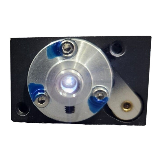
Inline TTL Shutter
INLINE-TTL-S
A
Installation and Operation Manual
Document Number 000-10000-090-02-0505
Ocean Optics, Inc.
Offices:
830 Douglas Ave., Dunedin, FL, USA 34698
Phone 727.733.2447
Fax
727.733.3962
8 a.m.– 8 p.m. (Mon-Thu), 8 a.m.– 6 p.m. (Fri) EST
Ocean Optics B.V. (Europe)
Geograaf 24, 6921 EW DUIVEN, The Netherlands
Phone 31-(0)26-3190500
F ax
31-(0)26-3190505
E-mail:
Info@OceanOptics.com
Info@OceanOpticsBV.com
Orders@OceanOptics.com
TechSupport@OceanOptics.com (Technical support)
Product
(General sales inquiries)
(European sales inquiries)
(Questions about orders)
Advertisement
Table of Contents

Subscribe to Our Youtube Channel
Summary of Contents for Ocean Optics INLINE-TTL-S
- Page 1 Ocean Optics, Inc. Offices: 830 Douglas Ave., Dunedin, FL, USA 34698 Phone 727.733.2447 727.733.3962 8 a.m.– 8 p.m. (Mon-Thu), 8 a.m.– 6 p.m. (Fri) EST Ocean Optics B.V. (Europe) Geograaf 24, 6921 EW DUIVEN, The Netherlands Phone 31-(0)26-3190500 F ax 31-(0)26-3190505 E-mail: Info@OceanOptics.com...
- Page 2 Every effort has been made to make this manual as complete and as accurate as possible, but no warranty or fitness is implied. The information provided is on an “as is” basis. Ocean Optics, Inc. shall have neither liability nor responsibility to any person or entity with respect to any loss or...
-
Page 3: Table Of Contents
Document Summary ........................iii Product-Related Documentation....................iii Upgrades ......................... iii Chapter 1: Setup .................1 Overview.......................... 1 Unpacking ........................2 Contents .......................... 2 Chapter 2: INLINE-TTL-S Specifications ...........3 Operating Environment....................3 Specifications ........................3 Pinout Information ......................4 Pinout Diagram .......................... 4 Index.....................5 000-10000-090-02-0505... - Page 4 Table of Contents 000-10000-090-02-0505...
-
Page 5: About This Manual
Engineering-level documentation is located on our website at Technical → Engineering Docs. Upgrades Occasionally, you may find that you need Ocean Optics to make a change or an upgrade to your system. To facilitate these changes, you must first contact Customer Support and obtain a Return Merchandise Authorization (RMA) number. - Page 6 About This Manual 000-10000-090-02-0505...
-
Page 7: Chapter 1: Setup
UV/VIS-optical components. The shutter is controlled by a small circuit board that is powered by a 12 VDC signal. The circuitry in the INLINE-TTL-S monitors Pin 13 of the 15-pin D-Sub connector for a 5- volt TTL signal and triggers the shutter when the 5-volt signal is received. -
Page 8: Unpacking
Procedure To set up your Inline TTL Shutter, 1. Connect a UV or VIS optic to the SMA 905 Connectors on each end of the INLINE-TTL-S shutter. 2. Connect the 12 VDC power supply to the control box of the INLINE-TTL-S. -
Page 9: Chapter 2: Inline-Ttl-S Specifications
Chapter 2 INLINE-TTL-S Specifications This section provides information on the operating environment and physical specifications of the INLINE-TTL-S. It also provides pinouts for the 15-pin connector. Operating Environment The following table provides information on optimizing the operating environment of your INLINE-TTL- Operating Environment The INLINE-TTL-S Unit . -
Page 10: Pinout Information
2: INLINE-TTL-S Specifications Pinout Information The following table contains pinout information for the INLINE-TTL-S: Description Ground TTL Signal na = not applicable Pinout Diagram 000-10000-090-02-0505... -
Page 11: Index
Index document setup, 1 audience, iii specifications, 3 purpose, iii summary, iii unpacking procedure, 2 upgrades, iii operating environment, 3 what's new, iii package contents, 2 pinouts, 4 product-related documentation, iii 000-10000-090-02-0505... - Page 12 2: INLINE-TTL-S Specifications 000-10000-090-02-0505...
Need help?
Do you have a question about the INLINE-TTL-S and is the answer not in the manual?
Questions and answers