Table of Contents
Advertisement
Quick Links
Advertisement
Table of Contents

Summary of Contents for Eletta D Series
-
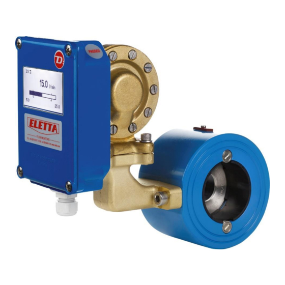
Page 1: D-Series Flow Monitor
D-series Flow Monitor Manual... -
Page 2: Table Of Contents
Contents D-series Flow Monitor ...................... 1 Manual ..........................1 Contents ........................... 2 About this Manual ......................4 Proprietary Rights ......................4 Distributors ........................4 Customer Service ......................4 1 General Information ...................... 5 1.1 Description _________________________________________________________________ 5 1.2 Overview Control Unit ________________________________________________________ 6 1.3 Overview Pipe Section ________________________________________________________ 6 1.4 Pipe Dimensions _____________________________________________________________ 7 1.5 PED Certification _____________________________________________________________ 7... - Page 3 3.1.4 Options __________________________________________________________________ 25 3.1.5 Simulation _______________________________________________________________ 27 3.1.6 Info _____________________________________________________________________ 27 3.1.7 Factory Default ____________________________________________________________ 28 3.1.8 Calibrate _________________________________________________________________ 29 3.2 Change of Flow Direction _____________________________________________________ 31 3.3 Change of Flow Range ________________________________________________________ 31 4 Differential Pressure Measurement ................34 4.1 The Differential Pressure Principle ______________________________________________ 34 4.2 Pressure Drop ______________________________________________________________ 34 5 Trouble Shooting ......................
-
Page 4: About This Manual
Any other use of data and information is strictly prohibited without prior written permission from Eletta Flow AB, Sweden. Distributors Eletta has appointed a number of distributors all over the world. You will find more information about your closest distributor at our web site www.eletta.com, or by contacting our Customer Service Center. -
Page 5: General Information
1 General Information 1.1 Description The D-series Eletta Flow Monitor are used to measure and control flows of liquids and gases in threaded pipes with sizes DN15-DN40 and flange fitted pipe sizes DN15 to DN500. The Eletta Flow Monitor is based on the proven and dependable differential pressure principle, using interchangeable orifice plates for different measuring ranges. -
Page 6: Overview Control Unit
1.2 Overview Control Unit The Control Unit mainly contains the diaphragm housing and two circuit boards (the display circuit board and the power circuit board). The mechanical movement on the diaphragm lever created by the differential pressure in the pipe is acting on the rubber diaphragm in the same way as our other mechanical Flow Monitors. -
Page 7: Pipe Dimensions
A2. Internal manufacturing checks with monitoring of the final assessment, for category 2. Performed by Kiwa Inspecta AB. PED Declaration of conformity will be sent to you upon request and are also available on www.eletta.com. 1.6 EMC... -
Page 8: Type Plate
1.7 Type Plate Each Eletta Flow Monitor wear a Type Plate with technical data and specifications for the specific Flow Monitor. The Type Plate is located on the top of the Control Unit shown as below. Always check that the information on the Type Plate corresponds to what you have ordered. -
Page 9: Specifications
Monitor Flow Range. For example: If you have a flow of 110 l/min maximum and the normal flow is at 90 l/min, choose the Eletta Flow Monitor D2 with a flow range of 60 - 120 l/min. This will give you... -
Page 10: Installation
2.2 Preparations Before installation, we kindly ask you to perform the following steps: 1) Eletta recommends that you choose a correct position for installation of the Flow Monitor in your pipe system. The following table serves as a guideline. Process Media... -
Page 11: Installation Of The Flow Monitor
2.3 Installation of the Flow Monitor Note! Before starting the installation, please make sure that the piping is not pressurized from flow of liquid or gas! The Flow Monitor can be installed vertically, horizontally or angular. We do not recommend to install the Flow Monitor upside down, this is to prevent particles in the fluid to collect in the diaphragm housing. - Page 12 Fittings with an inside diameter that is smaller than the inside diameter of the Eletta Pipe Section may create a media jet stream of the media, this will result in a too low differential pressure and thereby causing a measurement error. See chapter 7 “Dimension Tables”...
- Page 13 Therefore, the recommendation above serves only as a guideline, i.e. a method that has proven to secure the measurement accuracy. If shorter runs are used, Eletta neither can guarantee the specified maximum accuracy, nor predict the flow in your specific application.
-
Page 14: Installation And Changing Of The Control Unit
2.4 Installation and Changing of the Control Unit All Eletta Flow Monitors are designed to achieve a modular and versatile instrument. The modular system allows you to upgrade, rebuild or add other features to your already installed Flow Monitor. For example: if you would like to upgrade a V or S-series with mechanical micro switches to a D- series including user settable relay switches and a mA, pulse or frequency output this is easily done. -
Page 15: Separate Mounting Of The Control Unit And Pipe Section
2.5 Separate Mounting of the Control Unit and Pipe Section Sometimes, the pipe Section and the Control Unit need to be separately located from each other. The reasons could be lack of space, high system media temperature or vibrations. The following section explains our Separate Mounting kit. -
Page 16: Separate Mounting - Installation
2.5.1 Separate Mounting - Installation We recommend installing the Pipe Section and the Control Unit as close to each other as practically possible. This will facilitate future trouble-shooting and on-site calibration. Assemble the Control Unit adapter to the Control Unit (see chapter 2.4 on how to separate Control Unit and Pipe Section). -
Page 17: Electrical Installation
2.6 Electrical Installation Display - : Down/Decrease + : Up/Increase C : Cancel M : Menu/Confirm Connector/Terminal block for alarm relay L1 Connector/Terminal block for alarm relay L2 Connector /Terminal block for power supply Jumper 1 Connector/Terminal block for outputs Note! The jumper fitting only affect the Pulse/freq output. - Page 18 All terminal block connections are to be made through the included cable gland (PG9) and please note that you have two alternate mounting options of the cable gland depending on what side you want to enter with the cables. We recommend the entry of the cables to be placed in a downward or sideway direction, to avoid moisture/water to collect in the enclosure.
-
Page 19: Hart Protocol Specification
0, 1, 2, 3, 6, 7, 8, 11, 12, 13, 14, 15, 16, 17, 18, 19 Supported, use the “HART Multidrop” setting in the settings menu Multidrop to lock the loop current to 4 mA Default Device Tag “ELETTA D” Burst mode Not supported Default Polling Address 2.6.3 HART Identifying Device The D-Series uses “0”... -
Page 20: Zero Based / Non-Zero Based Calibration
2.6.2 Zero based / Non-Zero based Calibration The analogue 4-20 mA output signal is pre-calibrated in our flow rig to give you a zero-based signal. This means that you will get a fixed 4 mA reading when there is no flow and up to the minimum measurable flow reading possible i.e. -
Page 21: Operation
3 Operation 3.1 Display Settings To change any information on the display, press the button “M” and hold for 2 sec. to reach the “Main menu”. Note! No changes you make in the “Main menu” except Alarm and Simulation will have an effect on the flow meter function;... -
Page 22: Language
3.1.2 Language Scroll in the menu up and down with the buttons + or -. When the text is highlighted (black), it means that you can change the parameters. To change “Language”; press once more on the “M” button, to move to the right and change language with the buttons “+”... - Page 23 Output Scroll down to “Output” with the “-“ button and press the “M” button. In this menu you can activate the frequency output. The output is an open collector type, max 24 VDC/100mA. It gives a frequency of 200 to 1000 Hz or pulse.
- Page 24 Hysteresis The hysteresis is necessary to avoid the alarm to ripple (go on and off) when the flow is close to the set point. The hysteresis is changeable separate for each alarm between 2.5, 5 and 10% (of Q max). To change the hysteresis, you scroll to that value you want to change and then press the ”M”...
-
Page 25: Options
Scroll down with the “-“ button to "Polarity" and press the "M" button to set the polarity to positive or negative. Confirm the choice with “M” button. To leave this menu, scroll down to “Return” and press “M”, or hold “C” button during 2 sec. “Return” takes you back one step in the menu, the “C”... - Page 26 Display Depending on the mounting orientation of the Flow meter, the display can be rotated in 4 different angles, 0°, 90°, 180°and 270°. To change the orientation, scroll down to “Display” and press “M” and when “Rotate” is highlighted press “M” to move to the right. Use “+” or “-“...
-
Page 27: Simulation
3.1.5 Simulation This function gives you the possibility to create and simulate a real mA- signal from the unit even if you don’t have any flow. For example, you want to check other instruments or functions in your system. In this case you can simulate a desired flow or mA-signal from the unit. -
Page 28: Factory Default
If you change turn down you need to change both the orifice plate and springs within the diaphragm housing, you also need to do a recalibration. Do not change turn down without consulting with the Eletta factory first. Change flow range for a new orifice Scroll down to “Q unit”... -
Page 29: Calibrate
3.1.8 Calibrate Note! The Flow Meter is already calibrated from factory and it shall normally not be necessary to recalibrate. If you still want to do this, you need a master meter so you can adjust to a correct flow. A new flow calibration will overwrite the old factory calibration and it’s not possible to recall it. - Page 30 After the last calibration point you get a confirmation whether the calibration was “OK” or “Failed”. If the calibration was OK, the new calibration will be saved as default in the E²-memory and the display goes back to the factory default menu. To leave the menu, scroll down to “Return”...
-
Page 31: Change Of Flow Direction
In each case of changing the orifice plate in-field, we kindly ask you to first contact your distributor or Eletta for advice about the correct orifice plate. The properties of each orifice plate are carefully calculated and designed to match the specific conditions of your installation. - Page 32 For threaded model –GL Untighten the bolts that hold the Pipe Section between the flanges in the piping (do not remove the threaded parts from the piping). Remove only the number of bolts necessary to pull the Monitor from the piping, normally it takes only one bolt from the highest position, to get the Monitor out. Take out of the spacer that holds the orifice plate.
- Page 33 For flanged model FA- Follow the procedure above to loosen the pipe section from the counter flanges in the piping system, but note that the spacers are held in place with two screws, which has to be untightened before removal For flanged model FSS- In this model, there is no loose replaceable orifice plate and therefore it is necessary to change the complete Pipe Section to achieve a new flow range.
-
Page 34: Differential Pressure Measurement
Q = √ΔP. 4.2 Pressure Drop Since the Eletta Flow Meter is based on the Differential Pressure Principle, it is inevitable that a small permanent system pressure drop is caused. The reason is that the orifice plate reduces the flow area inside the pipe, and this will affect the pressure. - Page 35 Example: For the Eletta Flow Monitor D2-GL15 with a flow range of 10-20 l/min, the following example can be used for how to calculate the ΔPp (permanent pressure drop) at 15 l/min for the said Monitor: d = 10,2 mm D = 16,0 mm This gives a ß...
-
Page 36: Trouble Shooting
The most likely problem is that the diaphragm inside the diaphragm housing is broken and needs replacement. A new diaphragm is available to buy as a spare part. Contact the Eletta factory if there is any uncertainty on how to change the diaphragm. If there is liquid inside the blue housing, the problem is probably a broken lever that goes from the diaphragm housing into the blue housing. -
Page 37: Spare Parts
6 Spare Parts 6.1 BOM Drawing D-GL/FA 2021-09-06 70C2E22... - Page 38 2021-09-06 70C2E22...
-
Page 39: Bom Drawing D-Gss/Fss
6.2 BOM Drawing D-GSS/FSS 2021-09-06 70C2E22... - Page 40 2021-09-06 70C2E22...
-
Page 41: Weight And Dimensions
7 Weight and dimensions 2021-09-06 70C2E22... -
Page 42: Measuring Ranges
8 Measuring Ranges The tables below are showing the standard measuring ranges for our Flow Monitors. The tables work as a guideline of what range that is achievable for different Pipe Sections and dimensions. It is possible to order different measuring ranges than indicated in the tables. 2021-09-06 70C2E22... -
Page 43: Recycling
Please contact your local authority or your household waste disposal service for further details of your nearest designated collection point. Correct product disposal saves resources and prevents negative effects on human health and the environment. Eletta Flow AB P.O. Box 5084 SE-141 05 Kungens Kurva SWEDEN E-mail info@eletta.com...
Need help?
Do you have a question about the D Series and is the answer not in the manual?
Questions and answers