
Related Manuals for Halytech Illuminator

Summary of Contents for Halytech Illuminator
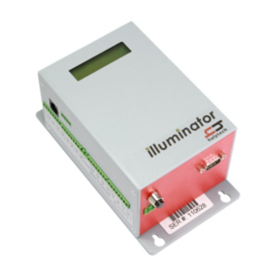
- Page 1 HALYTECH Illuminator User Manual Illuminator Floodlight Control and Facility Monitoring System USER MANUAL Illuminator User Manual Version 3.21 Copyright © Halytech All rights reserved Page 1...
- Page 2 All title and copyrights in and to the software (including but not limited to any text, instructions, code, “applets” incorporated into the software, images, photographs, animations, video, audio and music) are owned by Halytech. You may not reverse engineer, decompile, or disassemble this software for any purpose. No...
-
Page 3: Table Of Contents
Inputs (Advanced Use Only) ............................ 12 Auxiliary Connectors ..............................14 Numeric Keypad ..............................15 Setting up an Illuminator for the first time ....................... 16 Change Location and Lighting Setup ........................17 Setting Date and Time ............................. 19 ... -
Page 4: Introduction
It includes all software, hardware and a cellular phone module. Setting up and interrogating an Illuminator is a simple matter of viewing pages with any standard web browser. An Illuminator can be accessed either locally via a direct cable connection or remotely via internet or by sending and receiving SMS messages. -
Page 5: Overview Of Floodlight Control
This is the most often used mode where the lights are controlled directly by users during allowed periods of time. The Illuminator recognises two different types of users: an administrator and a number of “normal users”. The administrator has complete control over all floodlights. He or she can turn on and turn off any light at any time, without time off delay. - Page 6 Automatic e-mail reports An Illuminator can be set up to send daily e-mail reports. At 3:00 AM, an e-mail will be sent to up to three recipients. Each e-mail has a spreadsheet file attachment containing data logged over the recent day(s).
-
Page 7: Controls
100 ms. Event inputs are suitable for monitoring pulses that occur less frequently than once every 30 seconds. Each time an event occurs, the Illuminator logs the time its occurrence as well as the total number of events. The total will roll-over from 99,999 to 0. -
Page 8: Alarms (Advanced Use Only)
(Please see “Resetting Alarms” section for more details). If an alarm is reset but its trigger source is still in the active state, a new alarm sequence will NOT commence. Rather, the Illuminator will wait for the trigger source to first go inactive. Logger The Illuminator incorporates a high capacity solid-state data logger. -
Page 9: Web Server
Web Server A sophisticated web server is built into every Illuminator. It allows users to communicate with the Illuminator using the familiar “Internet surfing” approach. You can use any computer regardless of type and operating system to connect to an Illuminator. NO SPECIAL SOFTWARE is required. -
Page 10: Physical Connections
Using tools to tighten antenna connectors may damage them, voiding the warranty. Power Illuminator does not have an ON / OFF switch. The unit starts operating as soon as power is applied. The unit is fitted with two power connectors: ... -
Page 11: Controls
DC power supplies. A set of protection diodes is provided with each Illuminator. The circuit diagram below shows how to interface the Illuminator to the isolation relays. (Only a single control is shown for clarity.) -
Page 12: Inputs (Advanced Use Only)
An example of the external isolation relay setup is shown below in the picture. This particular setup is configured for driving 4 contactors – hence there are 4 isolation relays. Your electrician will be able supply the isolation relays as a part of the Illuminator installation. Inputs (Advanced Use Only) Inputs are connected to terminals marked IN1 to IN8. - Page 13 HALYTECH Illuminator User Manual 2. “ANALOGUE” type accepts an analogue voltage from 0 – 2.5V. The following diagrams show wiring details for most common sensor types. (i) 2-WIRE 0 - 20 mA and 4 – 20 mA current loop sensors require an external 120 Ohm, ¼...
-
Page 14: Auxiliary Connectors
ILLUMINATOR AUXILIARY CONNECTORS Local Area Network (LAN) connector is used for connections to a PC or to a LAN. AUX1 connector is not used in a standard Illuminator. It is reserved for future enhancements and special applications. The optional keypad plugs into AUX2 connector. -
Page 15: Numeric Keypad
An optional numeric keypad can be used to control floodlights. It is provided for users who do not have access to mobile phones. The keypad can be added at any time. The Illuminator will automatically recognise the keypad and start acting on its commands. -
Page 16: Setting Up An Illuminator For The First Time
A new Illuminator must be connected to a mobile telephone network by inserting a valid SIM card. Please refer to Appendix C for details. A new Illuminator is shipped from the factory with a default, generic setup. You will need to change this setup to customise the Illuminator for your application. -
Page 17: Change Location And Lighting Setup
'Turn off delay (minutes)' is useful for classic (non-LED) lights. If a user commands the Illuminator to turn the lights off, the command is accepted but the lights are kept on for the number of minutes entered here. This gives a chance to a new user to turn the lights back on without having to wait for the warm-up period. - Page 18 Only two out of eight Illuminator controls are needed in this example. Let’s assume that Illuminator Control 1 is driving the contactor that turns on the first half of the lights, and that Illuminator Control 2 is driving the contactor that turns on the second half of the lights.
-
Page 19: Setting Date And Time
Setting Date and Time If not already displayed, access the “Change Setup” page as described in “Setting up an Illuminator for the first time”. Click “Time & Date”. Confirm that the displayed date and time are correct. If you wish to change the date and/or time simply enter the new values or click “Set from computer”... -
Page 20: Change User And Password
Failing to enter them, disables all access to the Illuminator. Similarly, if a valid sequence is entered, but no activity takes place for 10 minutes, the access is revoked and the user must again log in. -
Page 21: Setting Up Network Parameters
Network settings Please refer to Appendix A for more information about initial connection of an Illuminator to a Local Area Network (LAN). To set up Network parameters, access the “Change Setup” page as described in “Setting up an Illuminator for the first time”... - Page 22 Select the GPRS connection method. GPRS connection will only work if you have a valid SIM card installed in the Illuminator and if the antenna is connected. Please refer to Appendix C for information on how to source and install a SIM card.
-
Page 23: Setting Up Email Parameters
Test email address: Test e-mails are sent to this address. This is a special feature of the Illuminator allowing a rapid and user friendly way of setting up and verifying Illuminator e-mail connectivity. Please refer to Appendix D for details. -
Page 24: Network Glossary
However, here is a brief explanation of each parameter noting any special relevance to the Illuminator implementation: My IP Address (*): current IP address of Illuminator. This is the same as the value shown on the LCD display. Network Mask (*): Network mask. This is the same as the value shown on the LCD display. -
Page 25: Save Setup To Disk
Illuminator User Manual Save Setup to Disk Once you have configured an Illuminator for your application you can save all the settings on your computer. This is useful as a backup or if you have multiple Illuminators and you wish to save a “template”... -
Page 26: Normal Operation
Communicating with the Illuminator is identical to “Surfing the Internet”. Information is displayed by clicking links and buttons. You can connect to an Illuminator either locally via a cable or remotely via internet or a dial-up modem. Once connected, operation is identical regardless of connection. The only difference you may notice with a remote connection is a slightly slower response. - Page 27 HALYTECH Illuminator User Manual The column labelled ”Today's Operation” shows how the scenario is set up to work today. Possible values are: “Closed” – the scenario has been closed by the administrator “None” – the scenario is open but no access is allowed today ...
-
Page 28: Clubs
HALYTECH Illuminator User Manual Clubs The terms “Users” and “Clubs” are interchangeable in this manual. This “Clubs” screen displays all clubs, their PINs and light scenario access rights. To change any of the details for a Club, click on the corresponding “Change” on the same row. -
Page 29: Report
You can request a light usage report at any time. To obtain the report click “Report” on the blue pane on the left. The following screen will be displayed: The Illuminator stores the most recent 1000 events in its memory Data is downloaded “backwards” in time. In other words, the most recent records are downloaded first. - Page 30 Please refer to Advanced Operation - Automatic Daily E-mail Reports for details. It is possible to connect an Illuminator to electricity meters to measure exactly how much electricity is used by lights at each field. Once this is set up, the report will have an additional column showing electricity use.
-
Page 31: Advanced Operation
Advanced Operation Automatic Daily E-mail Reports Illuminator can be set up to automatically send daily e-mail reports. Each e-mail has a spreadsheet file attached to it. The file contains all data logged over the previous day(s). Reports can be sent to up to three different recipients. Up to three attempts will be made to send a daily e-mail report. -
Page 32: Inputs
Illuminator User Manual Inputs Decide how your inputs will connect to the Illuminator. As described earlier in “Inputs” every Illuminator input can be configured in one of the following five modes: switch closure (digital), counter(digital), event (digital), analogue and disabled. -
Page 33: Calibrating Counter Inputs (If Present)
0 to 9,999.9. It is often desirable to pre-set the counter to a particular value. Following our previous example, you may want to make the Illuminator counter value the same as the reading on the meter. Page 33... -
Page 34: Scaling Event Inputs (If Present)
If not already displayed, access the “Change Setup” page as described in “Setting up an Illuminator for the first time” earlier in this section. Select ”Calibrate <name of input>” from “Select Input to Calibrate”. A page giving calibration choices will be displayed. -
Page 35: Viewing Current Inputs
If not already displayed, access the “Change Setup” page as described in “Setting up an Illuminator for the first time” earlier in this section. Select ”Calibrate Light Level” from “Select Input to Calibrate or Scale”. A page giving calibration choices will be displayed. Select “2- point calibration”... -
Page 36: Monitoring Electricity Use
HALYTECH Illuminator User Manual Monitoring Electricity Use You can connect electricity meters with pulse outputs to an Illuminator. This will allow you to monitor exactly how much electricity is being used by each control and optionally include it in reports. -
Page 37: Setting Up Alarms
SMS Sending: enabled If not already displayed, access the “Change Setup” page as described in “Setting up an Illuminator or the first time” earlier in this document. Click on “Change Alarm 1 Settings”. Fill in the form with the details above. -
Page 38: Viewing Current Alarms
ALL active alarms may be reset at once by clicking on the link at the bottom of the main pane. If there are no active alarms, the command will be ignored. Alarms may also be reset by sending an SMS the Illuminator. Please refer to the section “SMS Commands” for details. -
Page 39: History
HALYTECH Illuminator User Manual History In addition to Usage Reports described previously, the Illuminator also logs “raw data”. This data includes all activity including: 1. Input changes 2. Control output changes 3. Alarm activation and resets 4. SMS transmissions and their outcomes 5. -
Page 40: Front Panel Display
Illuminator User Manual Front Panel Display The Illuminator is equipped with a two-line display and a one-key keypad. They are used for quick operational checks and basic setup. Their convenience lies in the fact that using them requires no external equipment such as laptop computers or mobile phones. -
Page 41: Sms Commands
123402# The format of Floodlight Control Commands is described in “Overview of Floodlight Control”. After an Illuminator receives an SMS command it will interpret it and act on it. Valid commands will be acknowledged with a return SMS: <Location>: OK SMS command Invalid commands will be ignored. - Page 42 HALYTECH Illuminator User Manual NOTES: 1. Commands may be in lower or upper case or a combination of both 2. There must be only one space between the words of a command 3. SMS commands will be ignored while in the Remote Access mode. Therefore if an SMS command is not acknowledged by a return SMS within approximately 1 minute, send the command again after a short period of time.
-
Page 43: Sms Alarms
The alarm sequence may be reset simply by replying with the received message (no typing required !!), or by replying with RST AL1 or by connecting to the Illuminator with a PC and resetting the alarm as described in “Resetting Alarms”... -
Page 44: Software Upgrade
‘*’ is the CLEAR key. Pressing it clears the keypad and turns the red light off. The keypad command is sent to the Illuminator immediately following the pressing of the ‘#’ key. A successful command is acknowledged with three short beeps. An invalid command is indicated by a single long beep. -
Page 45: Appendix A: Connecting To An Illuminator Locally
1. Turn your computer on but do not connect it to the Illuminator yet. 2. Turn on the Illuminator by pressing and holding the button on the front panel for two seconds. (The unit must be turned on, i.e. the display must be showing something before you can establish a local connection.) - Page 46 6. Select “Obtain DNS server address automatically” 7. Click OK 8. Click OK 9. Close the Network Connections window In the unlikely event that you want to connect the Illuminator to a local area network (LAN), proceed as described next. Page 46...
-
Page 47: Connecting To An Existing Network (Lan)
Cancel ? A long press now will cancel all changes and return the display to normal operation. 11. You must power down and then power up the Illuminator for the new values to take effect. You can connect the Illuminator to your network with a standard RJ-45 network cable. Cables of various lengths are available from Halytech and most electronics and computer retailers. -
Page 48: Appendix B: Connecting To An Illuminator Remotely
1. You must use a Telstra post-paid SIM card enabled for dynamic public IP address (Please refer to Appendix C for details on how to do this.) 2. Illuminator WAN method must be set to "GPRS" and APN needs to be set to "telstra.extranet"... -
Page 49: Appendix C: Connection To Mobile Network
Appendix C: Connection to Mobile Network Illuminator units are fitted with a 3G or a 4G modem. You will need to source a SIM card from a mobile telephone network provider in order to allow light control by SMS, to send automatic reports by email and to let you connect to the Illuminator remotely. - Page 50 HALYTECH Illuminator User Manual 2. By looking through the slot, you will see the SIM card slot with a black locking lever to the left of it. Holding the SIM card level with the locking lever, gently push the SIM card into the exposed slot until it clicks in.
-
Page 51: Appendix D: Testing E-Mail Connectivity
“Test e-mail address” as configured in the E-mail Settings browser screen. Sending Test e-mails Once you set up a new Illuminator and enter all required Network / E-mail parameters ensure that it is connected to the appropriate network as selected by the E-mail sending method. -
Page 52: Appendix E: Logged Data Format
Illuminator User Manual Appendix E: Logged Data Format The Illuminator logs data internally in an efficient binary format. The internal binary format is converted into a standard “CSV” (Comma separated values) file before each download. A CSV file is readable by most spreadsheet and database programs. - Page 53 HALYTECH Illuminator User Manual 2999 2999 123411# Floodlight keypad command text Table decode: input number ( 0 – 7 ) STATE digital status state ( 0 = OFF, 1 = ON) CNT# control number ( 0 – 3 ) alarm number ( 0 – 7 ) alarm number ( 1 –...
Need help?
Do you have a question about the Illuminator and is the answer not in the manual?
Questions and answers