Table of Contents
Advertisement
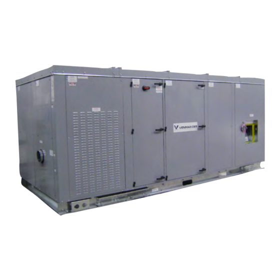
VHC
Energy Recovery Ventilators with Enthalpy Wheels and
Integrated Heating and Cooling
Installation, Operation and Maintenance Instructions Manual
Capacity: 800 to 5,500 cfm
Model: VHC-36, VHC-42, VHC-50
WARNING
Improper installation, adjustment, alteration, service or
maintenance can cause injury or death. Read the instal-
lation, operation and maintenance instructions thor-
oughly before installing or servicing this equipment.
IMPORTANT
The use of this appendix is specifically intended for a
qualified installation and service agency. A qualified in-
stallation and service agency must perform all installation
and service of these appliances.
FOR YOUR SAFETY
What to do if you smell gas:
1. Open windows if appliance is indoors.
2. Do not touch electrical switches or use any phone
in the building.
3. Extinguish any open flame.
4. Leave the building immediately.
5. Immediately call Gas Supplier.
Advertisement
Table of Contents

Summary of Contents for Nortek VENMARCES VHC-36
- Page 1 Energy Recovery Ventilators with Enthalpy Wheels and Integrated Heating and Cooling Installation, Operation and Maintenance Instructions Manual Capacity: 800 to 5,500 cfm Model: VHC-36, VHC-42, VHC-50 FOR YOUR SAFETY WARNING What to do if you smell gas: Improper installation, adjustment, alteration, service or maintenance can cause injury or death.
-
Page 2: Table Of Contents
Table of Contents Nomenclature ..................................3 Safety Considerations ................................4 General Information ................................4 Recommended Spare Parts ............................4 Inspection on Arrival ...............................5 Unit Application Limitations ............................5 Installation ....................................5 Unit Location Requirements ............................5 Roofcurbs Supplied by Venmar CES (External Applications Only) ................6 Roofcurbs Supplied by Others ............................6 Rigging and Lifting the Unit ............................7 Exhaust Dampers ................................7 Field Fabricated Ductwork .............................8... -
Page 3: Nomenclature
Solutions, Variable Refrigerant Control (VRC) from Nortek Air Solutions and Tefzel from DuPont. Nortek Air Solutions, LLC d/b/a Venmar CES furnishes equipment pursuant to its then-current Terms and Conditions of Sale and Limited Warranty, copies of which can be found under the Terms & Conditions of Sale and Warranty link at www.nortekair.com. -
Page 4: Safety Considerations
Safety Considerations Warning, Caution and Important notes appear through- Hazards may exist within this equipment because it con- out this manual in specific and appropriate locations to tains electrical and numerous moving components. Only alert Installing Contractors and maintenance or service qualified service personnel should install or service this personnel of potential safety hazards, possible equipment equipment. -
Page 5: Inspection On Arrival
Inspection on Arrival Inspect the equipment exterior and interior for any dam- ceived Less Item #___”. Contact the factory immediately age on arrival that may have occurred during unit ship- if damage is found. No return shipment will be accepted ment and for shipped loose parts. -
Page 6: Roofcurbs Supplied By Venmar Ces (External Applications Only)
Roofcurbs Supplied by Venmar CES (External Applications Only) Roofcurbs supplied by Venmar CES should be mounted IMPORTANT as follows: The following items must be completed prior to setting • The roofcurb is shipped knocked-down with assem- the unit on the roofcurb: bly hardware and instructions provided. -
Page 7: Rigging And Lifting The Unit
Rigging and Lifting the Unit CES will not be responsible for any damage caused to IMPORTANT the unit casing during the lifting process. The lifting point The hoods for these units are not installed from the must be at the center of gravity to ensure that the unit is factory and must be installed on site. -
Page 8: Field Fabricated Ductwork
Field Fabricated Ductwork On bottom vertical duct connections, secure all ducts to square root of (4ab/Pi) where ‘a’ and ‘b’ are the rectangu- the roofcurb and building structure prior to unit installation. lar dimensions of the fan discharge opening. Roofcurbs Supplied by Venmar CES (External Applica- Refer to to determine the effect of undersized Appendix E... -
Page 9: Hood Installation
Hood Installation Intake and exhaust hoods for these models are shipped separately from the unit. To install hoods see Appendix B. A quick connect for the damper motors is provided to connect to the main body of the unit. Make sure that all screws are secured to maintain proper support and keep seals water-tight. -
Page 10: Electrical Connections
Electrical Connections panel of the unit eliminating any water penetration into the WARNING control box. When installed, the unit must be electrically grounded in A low voltage field wiring (FW) interface is provided near accordance with local codes or, in the absence of local the control panel (PNL) terminals for shipped loose or field codes, with the National Electrical Code, ANSI/NFPA 70, and/or the Canadian Electrical Code CSA C22.1. - Page 11 Unoccupied (Un) connect using two twisted pair cables, the first for power connection. The LinkNet cable needs to be balanced 100 If the contact opens or jumper removed on any of the ter- to 120 ohm nominal impedance twisted shielded pair minals 304, 305, 306, 307 or 308 the unit will turn off.
-
Page 12: Coil Or Water Source Heat Pump (Wshp) Piping Connections
Coil or Water Source Heat Pump (WSHP) Piping Connections for WSHP water line piping requirements Appendix I IMPORTANT and field mounted options and accessories. If the unit includes heating coil external connections and A water flow switch is recommended to be installed in line split system direct expansion (DX) cooling coil connec- to prevent possible freeze-up due to loss of water flow. -
Page 13: Condensate Drain Trap
Condensate Drain Trap Cooling coil drain pan is provided with a 1¼” MPT drain The trap height allows for the maximum suction pressure connection. A drain trap and condensate line of equal size after the cooling coil with intake damper, dirty pre and final must be field provided on the drain connection to prevent high efficiency filters, high efficiency heat wheel plus 1”... -
Page 14: Start-Up
Start-up Pre Start-up Procedure Before requesting start-up, check that the installation is 11. Check that ductwork is connected and complete. complete and unit is ready. Complete the pre start-up 12. Check that condensate drain connections have been check list below and in the for each unit as Appendix J trapped, installed correctly and filled. -
Page 15: Start-Up Procedure
Start-up Procedure To ensure proper operation of each unit, qualified per- air damper (if equipped) opens. After outside air sonnel should perform the start-up and complete the damper opens supply blower starts, exhaust air checklist below and the start-up form in damper (if equipped) opens;... -
Page 16: Optional Controls And Accessory Sequence And Interlocks
Optional Controls and Accessory Sequence and Interlocks Free Cooling Ventilation Control Power connected, unit ventilating, free cooling call. Wheel VHC units’ air volume with the VFD motor control option stops rotating. can be directly controlled by a CO ventilation control (ac- cessory or field supplied) by connecting normally open Variable Speed Setpoint Free Cooling high speed contacts to the supply and exhaust fan high... -
Page 17: Frost Control
Frost Control Variable Speed Drive Frost Prevention During cold temperatures, defrost and frost prevention are controlled by the unit’s integrated controls as follows. This variable speed frost control option is an exhaust air temperature controlled function that allows for continu- Recirculation and exhaust only defrost remove the frost ous ventilation by reducing the enthalpy wheel rotational from the enthalpy wheel to maintain proper operation but... -
Page 18: Airflow Balancing
Airflow Balancing Refer to for optional gas-fired furnace module Appendix K IMPORTANT air balancing information. The installation is to be adjusted On initial power up, the unit will perform a system check to achieve the air throughput within the range specified on and operate at high speed for five seconds. -
Page 19: Maintenance
Maintenance Please refer to for a recommended list of rou- Appendix O WARNING tine maintenance items and time intervals. A more detailed Disconnect the main power switch to the unit before per- description of major maintenance items follows. forming service and maintenance procedures. Refer to for more gas-fired furnace and Appendix K... -
Page 20: Fans
Fans To remove the motor and blower on units with a gas-fired WARNING furnace option or with top supply or exhaust discharge, Disconnect the main power switch to the unit before per- disconnect the four-wire service connector from the motor forming service and maintenance procedures. - Page 21 Both motor shaft and fan bore must be completely free of WARNING paint, grease, oil and dirt. If necessary, clean the surfaces Disconnect the main power switch to the unit before per- with non-petroleum based solvent, such as isopropyl forming service and maintenance procedures. alcohol.
-
Page 22: Enthalpy Wheel
Enthalpy Wheel a socket or wrench. Remove the beam and bearing as- WARNING sembly from the end of the wheel shaft. Loosen the four Disconnect the main power switch to the unit before per- Nyloc nuts (#1, Figure 10) holding the drive motor using forming service and maintenance procedures. -
Page 23: Testing And Replacement Of The Damper Actuator
Enthalpy Wheel Drive Belt Replacement WARNING and Tensioning Adjustment Disconnect the main power switch to the unit before per- forming service and maintenance procedures. CAUTION Face Seal Replacement and Adjustment When handling the enthalpy wheel, ensure not to dam- age the face of the wheel. CAUTION When handling the enthalpy wheel, ensure not to dam- The enthalpy wheel drive belt can be tightened by sliding... -
Page 24: Coils
Coils Coil fins can be cleaned by using steam with detergent, WARNING hot water spray or a commercial chemical coil cleaner. Disconnect the main power switch to the unit before per- After cleaning the coil, be sure to rinse thoroughly. forming service and maintenance procedures. -
Page 25: System Operation Check
Components of a Direct Expansion System WARNING The evaporator is that part of the low pressure side of the Disconnect the main power switch to the unit before per- refrigerant system in which the liquid refrigerant boils or forming service and maintenance procedures. evaporates, absorbing heat as it changes into a vapor. -
Page 26: Appendix A: Service Clearance Dimensions
Appendix A: Service Clearance Dimensions Figure A1: Base VHC 34.0” *56.0” Power line input [864] [1,422] control wiring 36.0” Control [914] Exhaust blower Electric post-heat Defrost or unoccupied recirc damper Cooling/ Supply heating blower coil 34.0” Electric [864] pre-heat **46.0” 34.0”... - Page 27 Figure A2: VHC with hoods *56.0” 34.0” Power line input [1,422] [864] control wiring 34.0” 36.0” Control [864] [914] Exhaust blower Electric post-heat Defrost or unoccupied recirc damper Cooling/ Supply heating blower coil Electric pre-heat **46.0” *56.0” 34.0” [1,168] [1,422] [864] Note: All dimensions in [ ] are millimeters.
- Page 28 Figure A3: VHC with integrated cooling ***48.0” *56.0” 34.0” Power line input [1,219] [1,422] [864] control wiring 12.0” 36.0” Control [305] [914] Compressor Exhaust blower Electric post-heat Defrost or unoccupied recirc damper Cooling/ Supply heating blower coil **46.0” 34.0” *56.0” [1,168] [864] [1,422]...
- Page 29 Figure A4: VHC with gas heat Power line input gas line input 34.0” *56.0” control wiring [864] [1,422] ***36.0” Control [914] Exhaust blower Electric post-heat Vent Defrost or termination unoccupied recirc Gas heater damper Cooling/ Supply heating blower Electric coil pre-heat 34.0”...
- Page 30 Figure A5: VHC with gas heat and integrated DX cooling Power line input gas line input ***48.0” *56.0” 34.0” control wiring [1,219] [1,422] [864] 12.0” ****36.0” [305] [914] Vent Compressor termination Control Exhaust blower Defrost or unoccupied heater recirc damper Cooling/ Supply heating...
- Page 31 Figure A6: VHC with water source heat pump Power line input control wiring 34.0” *56.0” [864] [1,422] 36.0” Control [914] Exhaust Coaxial coil blower Compressor Water inlet and outlet WSHP module connections Defrost or unoccupied recirc damper Cooling/ Supply heating blower coil 34.0”...
- Page 32 Figure A7: VHC with extended cabinet Power line input control wiring 34.0” *56.0” [864] [1,422] 36.0” [914] Control box Exhaust blower Defrost or unoccupied recirc damper Cooling/ Supply heating coil blower 34.0” Electric Electric post-heat pre-heat [864] **46.0” 34.0” *56.0” [1,168] [864] [1,422]...
- Page 33 Figure A8: VHC with extended cabinet and integrated DX cooling Power line input ***48.0” *56.0” 34.0” control wiring [1,219] [1,422] [864] 12.0” [305] Control Compressor 36.0” Exhaust [914] blower Defrost or unoccupied recirc damper Cooling/ Supply heating blower coil Electric post-heat **46.0”...
-
Page 34: Appendix B: Hood Installation
Appendix B: Hood Installation Figure B1: Outdoor VHC hood installation IMPORTANT Complete wire connections between the unit and the hood by matching the correct wire colors on the actuator with the wire colors on the schematic. VCES-VHC-IOM-1F – VHC-36, -42 & -50... -
Page 35: Appendix C: Rigging Drawing
Appendix C: Rigging Drawing Figure C1: VHC rigging Spreader bars CAUTION 1. Use spreader bars and cables to apply an even vertical lifting force only at all the lifting points to prevent damage to the unit casing. 2. Provide additional blocking and coverings (as required) to prevent damage to the unit finish and/or components. VCES-VHC-IOM-1F –... -
Page 36: Appendix D: Equipment Data
Appendix D: Equipment Data Table D1: VHC-36, -42 and -50 Equipment Data VHC-36 VHC-42 VHC-50 Fans Supply type – Belt drive, ODP Wheel type Forward curved Forward curved Forward curved Bearing Pillow block Pillow block Pillow block Motor (HP) 0.5 to 5 0.5 to 5 1 to 10 Supply type –... -
Page 37: Appendix E: Effect Of Undersized Straight Duct And Elbows On Forward Curved Fans
Appendix E: Effect of Undersized Straight Duct and Elbows on Forward Curved Fans Figure E1: Fan inlet and outlet duct elbow positions Figure E2: System effect factor – pressure drop curves for SWSI fans F G H I J K L 5.00 Position C 4.00... -
Page 38: Appendix F: Electrical Data
Appendix F: Electrical Data Table F1: Full Load Amperage (FLA) Voltage 208/1/60 230/1/60 208/3/60 230/3/60 460/3/60 575/3/60 Blower Motor 0.50 4.50 4.00 1.80 2.20 1.10 0.90 0.75 5.40 6.00 2.70 2.70 1.40 1.10 1.00 6.80 7.00 3.40 3.40 1.70 1.40 1.50 10.20 10.20... - Page 39 Table F3: Compressor Run Load Amperage (RLA) Voltage Compressor Cooling Type Tonnage 208/230/1/60 208/230/3/60 460/3/60 575/3/60 Air Cooled Single Circuit On/off 12.8 Two-stage 15.3 11.6 On/off 17.9 13.5 Two-stage 17.9 14.2 On/off 25.0 15.9 Two-stage 28.8 16.2 On/Off 28.3 19.0 20.4 On/off 23.2...
- Page 40 Table F3: Compressor Run Load Amperage (RLA) Voltage Compressor Cooling Type Tonnage 208/230/1/60 208/230/3/60 460/3/60 575/3/60 Water Cooled Single Circuit Two-stage 15.3 11.6 Two-stage 17.9 14.2 Two-stage 28.8 16.2 20.4 23.2 11.2 24.0 12.6 33.3 17.9 12.8 48.1 18.6 14.7 51.3 23.1 19.9...
- Page 41 Finding the Actual MOP Value Table F5: Dual Circuit Compressors From the calculated MOP value, select the next smallest For Dual Circuit On/Off Units value of protection from the Standard Overcurrent Protec- 6 tons Two 3 ton on/off compressors tion chart below to get the actual MOP value (maximum 8 tons Two 4 ton on/off compressors value of overcurrent device).
-
Page 42: Appendix G: Standard Field Wiring Terminals
Appendix G: Standard Field Wiring Terminals Control Field Wiring Figure G1: Electro-mechanical controls Low voltage terminal control consists of the following: 24 VAC+ 24 VAC− Electro-mechanical Controls Unit 304A OCCUPANCY Inputs CONTACT • Occupied ventilation timer/sensor UNOCCUPIED RECIRCULATION CONTACT (OPTIONAL) Dry contact –... - Page 43 DDC Controls Unit Figure G2: DDC controls Inputs 24 VAC+ • Occupied ventilation 24 VAC− Dry contact – OCCUPANCY CONTACT • Unoccupied recirculation (if equipped) UNOCCUPIED RECIRCULATION CONTACT (OPTIONAL) Dry contact – • Occupied recirculation (if equipped) OCCUPIED RECIRCULATION CONTACT (OPTIONAL) Dry contact –...
-
Page 44: Appendix H: Terminal Control Diagrams
Appendix H: Terminal Control Diagrams Occupied Ventilation Occupied Timer Sensor Occupied ventilation is achieved by closing the occupancy Occupied ventilation is achieved by connection to the contact to the terminal interface shown in Figure H1. terminal interface shown in Figure H2. These terminals re- These terminals require a dry contact which could be pro- quire a dry contact which could be provided by a number vided by a number of types of controls such as a timer,... - Page 45 Unoccupied Recirculation VFD High Speed Control Supply fan recirculation for heating and cooling can be High speed fan control can be achieved by connecting dry achieved by connecting dry contact controls to the termi- contact controls to the field wired (FW) terminals 374 and nal interface provided in the control panel area.
- Page 46 Ventilation Control Smoke Detector VHC units’ air volume with the VFD motor control option Locate in a normally occupied area of premises. Recom- can be directly controlled by a CO ventilation control (ac- mended for compliance to NFPA 90A and IMC Code 606. cessory or field supplied) by connecting normally open VHCs can be equipped with a duct mount smoke de- high speed contacts to the supply and exhaust fan high...
- Page 47 Dirty Filter Sensor The VHCs can be equipped with dirty filter sensors which monitor the pressure across the filters and close the con- tacts when the filters become restricted with dirt. Field wired connections can be made to the terminal interface for both the supply and exhaust filter sensors.
-
Page 48: Appendix I: Water Source Heat Pump Water Line Piping Requirements And Field Mounted Options And Accessories
Appendix I: Water Source Heat Pump Water Line Piping Requirements and Field Mounted Options and Accessories IMPORTANT • Water source heat pump external water supply and return piping shall be in accordance with national and local codes. Line sizing, pressure limiting devices, backflow preventers, strainers, valves, flow temperature and pressure measuring, freeze protection and all other safety or control piping requirements for system operation are the sole responsibility of the Installing Contractor and/or Design Engineer. - Page 49 Freeze Protection The two-way motorized water shut-off valve is an ac- cessory item and consists of a 24 VAC NEMA 1 or 2 on/ A water flow switch and a temperature sensor as an op- off actuator with a temperature rating of −22°F to 122°F tion and mounted on the water return or leaving side of [−30°C to 50°C], nickel plated forged brass valve and the condenser are used to monitor the presence or ab-...
- Page 50 Table I3: Two-way Water Shut-off Valve Sizing and Technical Data Two-way Water Shut-off Valve* Condenser Circuit Minimum Condenser Pressure Tons Maximum Maximum Size Number US GPM Drop (PSI) Indoor PN Outdoor PN Cv1 Pressure (PSI) Pressure (PSI)* 500016467S 500027835 ¾ 500016467S 500027835 ¾...
- Page 51 Table I5: Indoor Three-way Valve Actuator Table I4: Three-way Technical Data Technical and Dimensional Data (2 to 5 tons) Service Chilled or hot water, 60% glycol Control On/off, floating point A-port B-port Nominal voltage 24 VAC 50/60 Hz Flow characteristic Modified for constant Equal percentage common port flow...
- Page 52 Table I7: Outdoor Three-way Valve Actuator Table I9: Indoor Three-way Valve Actuator Technical and Dimensional Data (2 to 5 tons) Technical and Dimensional Data (6 to 8 tons) Control 2–10 VDC, 4–20 mA 24 VAC ± 20% 50/60 Hz Power supply 24 VAC ±...
- Page 53 Table I11: Outdoor Three-way Valve Actuator Table I13: Indoor Three-way Valve Actuator Technical and Dimensional Data (6 to 8 tons) Technical and Dimensional Data (10 to 21 tons) 24 VAC ± 20% 50/60 Hz 24 VAC ± 20% 50/60 Hz Power supply Power supply 24 VDC ±...
- Page 54 Table I15: Outdoor Three-way Valve Actuator Table I16: Outdoor Three-way Valve Dimensions Technical and Dimensional Data (10 to 21 tons) (10 to 21 tons) 24 VAC ± 20% 50/60 Hz Value Nominal Size Dimensions (Inches [mm]) Power supply 24 VDC ± 10% Inches DN [mm] Running...
- Page 55 Water Valve Piping Arrangement Correct Piping It is important to follow the proper piping arrangement for Figure I11: Correct three-way diverting valve piping both two-way and three-way water valves. Incorrect pip- 1 input, 2 outputs ing arrangements will damage the unit. The field piping schematic is illustrated in Figure I8.
- Page 56 Figure I14: Valve and actuator assembly and WARNING installation Mechanical shock or vibration can cause permanent damage to the switch. Avoid dropping the unit on hard One screw attaches surfaces. actuator to valve 4 x 90° Four actuator mounting 2. Apply thread tape or sealant to the ½” male NPT positions mounting threads and install the flow switch in the Two-way flow pattern...
-
Page 57: Appendix J: Vhc-36, -42 And -50 Start-Up Form And Checklist
The BacStat II interface module (if equipped with DDC controls package and mounted remotely) may be temporarily connected at the unit for checkout. Ensure it is connected to the Net 2 contacts otherwise it will not give readings. Unit Identification Information Nortek Air Solutions 1502 D Quebec Avenue Project: __________________________________________... - Page 58 Serial Number: _____________________________________ Table J1: Pre Start-up Checklist Checklist Item Is the electrical disconnect set to the ‘Off’ position? Have obstructive packaging, objects, tie downs on fans and heat wheel been removed? Are fans and enthalpy wheel rotating freely? Are fan wheels and drive set screws tight? Are belt alignment and tension correct? Are air filters installed, clean or replaced? If filters are equipped with optional differential pressure switch, check desired setpoint does not exceed factory setting of 0.8”...
- Page 59 Serial Number: _____________________________________ Table J2: Start-up Checklist Checklist Item Before proceeding, complete the pre start-up checklist. Close all access panels or doors. Turn the main disconnect to the ‘On’ position. Set the timer, selector switch or BMS to close the contact for the scheduling mode desired and check operation and sequence.
- Page 60 Start-up Readings Serial Number: _____________________________________ • Allow unit to reach steady state before taking readings. • Complete based on options included with the unit. Table J3: Start-up Readings Mode of Operation Heating Cooling Nameplate voltage L1–L2 Power supply Voltage at disconnect L2–L3 no motors L1–L3...
- Page 61 Serial Number: _____________________________________ Table J3: Start-up Readings Mode of Operation Heating Cooling Discharge pressure – PSI Suction pressure – PSI Discharge temperature – °F Suction temperature – °F Superheat – °F Circuit #1 Sub-cooling – °F __ ½ __ ¾ __ Site glass oil level ___ Yes ___ Site glass clear...
- Page 62 This page intentionally left blank. VCES-VHC-IOM-1F – VHC-36, -42 & -50...
-
Page 63: Appendix K: Gas-Fired Furnace Module Installation And Maintenance
Appendix K: Gas-fired Furnace Module Installation and Maintenance servicing of the heating section. See Appendix A WARNING the required service clearance dimensions. Fire or Explosion Hazard 2. Do not install the appliance where it may be exposed to potentially explosive or hazardous atmospheres 1. - Page 64 away from any combustion air intakes according to Vent pipe must terminate at least 1 foot above the cabi- the installation. net. The vent must be located on the same side of the ap- pliance as the combustion air inlet opening. Condensation Outdoor Installation in the vent pipe is likely during heater start-up cycle and Air for Combustion...
- Page 65 nections, vent pipe diameter required and submittal for Table K1: VHC-36, -42, -50 Number of Furnace Vents, location. Vent Connection Size and Vent Pipe Diameter Number of Vent Indoor Installation Input Rating Vent Pipe Furnace Connection BTUH [Watts] Diameter Air for Combustion Vents Diameter 100,000–125,000...
- Page 66 Figure K4: Indoor vertical venting radation of building material by flue gases. The vent terminal must be located at least 1 foot [305 mm] Exhaust vent above grade, or in snow areas, at least 3 feet [1 m] terminal Roof line above snow line to prevent blockage.
- Page 67 Separated Combustion Air Intake Systems Figure K7: Separated combustion – horizontal venting On indoor units for operation with separated combustion 5 ft. [1.5 m] min. 25 ft. [15.2 m] Building overhang max. equivalent length air intake systems, the burner section is in a reasonably Pitch pipes down ¼...
- Page 68 Figure K8: Union installation WARNING Gas supply line 1. When pressure testing at ½ psi or less, close the manual shut-off valve on the appliance before testing. Ground joint union 2. When pressure testing gas supply line at ½ psi or with brass seat Manual gas higher, close manual gas valve and disconnect...
- Page 69 3. The heat capacity of the furnace is controlled by WARNING the burner orifices and the gas manifold pressure. Operation of the furnace module at vent temperatures The manifold pressure is factory set but should be below that specified for a Category III could result in checked at the time of start-up as described below.
- Page 70 Fenwal 35-61 Series Direct Ignition Control based on WARNING – FOR YOUR SAFETY the burner firing rate control (on/off, two-stage or full The use and storage of gasoline or other flammable va- modulation) and Troubleshooting Guide provided on pors and liquids in open containers in the vicinity of this the furnace at the end of this appendix.
- Page 71 13. Prior to completing the start-up, check the appear- Figure K13: Burner flame at high fire 3.5” w.c. ance of the main burner flame. See Figure K12 and manifold pressure draft inducer – high speed Figure K13 for flame characteristics of properly ad- justed natural gas systems.
- Page 72 Fenwal Series 35-6 Ignition Control the setpoint. Determine the cause of the reduced airflow and correct. Fault Conditions and LED Key LED steady on Internal control fault WARNING 1 Flash Combustion airflow fault A secure and effective functioning gas burner requires 2 Flashes Flame with no call for heat sufficient combustion gas exhaust discharge.
- Page 73 Parts and Service Department at: tion trials. If no flame is present at the flame sensor Nortek Air Solutions within 10 seconds, the spark and gas valve will be 1502 D Quebec Avenue de-energized.
- Page 74 2. The ignition control may also be manually reset, by 2. 24 VAC to is supplied to IC terminal TH, provided turning the thermostat down and back up to previ- limit switch is in closed position. ous temperature setting or removing power (24V) to 3.
- Page 75 MH Sequence of Operation – 20–100% tion trials. If no flame is present at the flame sensor Modulation with Two-speed Controller within 10 seconds, the spark and gas valve will be de-energized. A 15 second inter-purge period begins Fenwal 35-61 Series Direct Ignition Control, TR1 and the combustion blower continues to run.
- Page 76 12. If the signal increases above 5.3 VDC, the SC30 2. If the burners fail to light or carryover during a trial for relay closes powering terminal 6 on the TR1 and ignition, the control will attempt two additional igni- starts a second time delay of 15 seconds.
- Page 77 Table K3: LED Code Troubleshooting System Description Actions Code Check for open fuse or circuit breaker. Check for poor wiring connection. No power None On call for heat, nothing happens. Check for failed 24V transformer. to T1 Check if the manual reset high limit switch has tripped and determine cause and correct before resetting.
- Page 78 Table K3: LED Code Troubleshooting System Description Actions Code Verify gas supply available and operation of gas valve – manifold pressure at start of ignition cycle. Check for power to valve terminals Low and Com while spark is energized. Is spark present? If no, check igniter for debris between electrodes, cracked ceramic and check ignition wire for short to ground.
-
Page 79: Appendix L: Electric Heating Coil And Controls Information
Appendix L: Electric Heating Coil and Controls Information 2 – Electrical Installation of Electric Coil This electric heating coil module covered by this appen- Heaters dix is a component of a “Listed” product, subject to the guidelines of application as designated by the Certifying 2.1 Disconnect Power Source Agency and outlined in the Appliance Manufacturer’s in- Disconnect all power sources before opening the control... - Page 80 3 – Operating Electric Coil Heaters 4.2 Electrical Inspection Two weeks after start-up, all electric connections to con- 3.1 Minimum Airflow tactors should be checked and tightened up. Before each Ensure that sufficient airflow as marked on the nameplate heating season, check the resistance between the heating is passing through the heater.
-
Page 81: Appendix M: Enthalpy Wheel Pressure Drop Vs. Flow Formulae And Curves
Appendix M: Enthalpy Wheel Pressure Drop vs. Flow Formulae and Curves Figure M2: Pressure drop – 42” enthalpy wheel diameter Enthalpy Wheel Pressure Drop vs. Flow Formula 42” x 4” (Supply) Flow in cfm = pressure drop measured in inches w.c. / pressure drop coefficient based on enthalpy wheel size 42”... -
Page 82: Appendix N: Troubleshooting
Appendix N: Troubleshooting Table N1: VHC-36, -42 and -50 Troubleshooting Problem Cause Solutions Occupancy contact open. Check external wiring. Unit will not turn on. Unoccupied recirc contact open. Check the wiring in the control panel. Occupancy contact closed. Check the external wiring. Unit will not turn off. - Page 83 Table N1: VHC-36, -42 and -50 Troubleshooting Problem Cause Solutions Check if voltage is too low, wiring is incorrect, wire gauge Overload, fuse burnout. is sized correctly; replace blown fuse. Compressor runs but stops quickly. See solution for high pressure switch open and low Low or high pressure switch activated.
-
Page 84: Appendix O: Vhc-36, -42 And -50 Maintenance Summary Chart
Appendix O: VHC-36, -42 and -50 Maintenance Summary Chart Table O1: VHC-36, -42 and -50 Maintenance Summary Chart Semi- Item No. Description Note Monthly Quarterly Annually annually Inspect the general condition of the unit. Remove any dirt or debris. Check interior liners and partition for dirt buildup and General clean. - Page 85 Table O1: VHC-36, -42 and -50 Maintenance Summary Chart Semi- Item No. Description Note Monthly Quarterly Annually annually Clean the coils. Clean the drain pan. Coils Winterize water coils. Clean the drain trap. Check fluid level in drain trap. Check for refrigerant leak, look for oil on components. Verify proper superheat.
-
Page 86: Appendix P: Forward Curved Fan Bearing Relubrication Schedule
Appendix P: Forward Curved Fan Bearing Relubrication Schedule Fan Model ATL1 9-4 & ATL1 9-7 ATL1 10-7 & ATL1 10-9 ATL1 12-9 Class Bearing Size ¾ ¾ Bearing Model P2B-SCAH-012-FF P2B-SCAH-012-FF P2B-SCAH-100-FF 0.09 0.09 0.11 Relubrication Grease Qty. (oz.) Frequency of Frequency of Frequency of Relubrication... -
Page 87: Appendix Q: How To Measure, Assemble And Install Link Belt
Appendix Q: How to Measure, Assemble and Install Link Belt How to Measure Assembly Figure Q1: Multi- 1. Hold belt with tabs pointing outward. Pull belt tight around sheaves to link drive belt 2. Place end tab through two links at once. check hand tight length, overlapping 3. - Page 88 Retensioning IMPORTANT Like all high performance V-belts, PowerTwist Plus V- With drive ratios around 1:1, it may be necessary to add belts require the maintenance of correct drive tension to back one link to allow belts to be rolled on. This does not operate efficiently.
-
Page 89: Appendix R: Adjusting Refrigerant Charge
Appendix R: Adjusting Refrigerant Charge Checking Liquid Sub-cooling CAUTION 1. Measure the temperature of the liquid line as it leaves The Clean Air Act of 1990 bans the intentional vent- the condenser coil. ing of refrigerant (CFCs and HCFCs) as of July 1, 1992. 2. - Page 90 Adjusting Sub-cooling and Superheat Table R2: R410a Refrigerant Temperature vs. Pressure Temperatures °F PSIG °F PSIG °F PSIG °F PSIG °F PSIG 1. The system is overcharged if the sub-cooling tem- 78.3 47 134.7 74 213.7 101 321.0 128 463.2 perature is too high and the evaporator is fully loaded 80.0 48 137.2 75 217.1 102 325.6 129 469.3 (low loads on the evaporator result in increased sub-...
-
Page 91: Appendix S: Temperature Rise Over Gas-Fired Furnace
Appendix S: Temperature Rise Over Gas-fired Furnace Table S1: VHC-36 Temperature Rise Over Gas-fired Furnace (°F) – 5:1, 2:1 and On/Off Models Air Volume (CFM) 100 MBH 125 MBH 200 MBH 94.1 83.6 1,000 75.2 94.1 1,100 68.4 85.5 1,200 62.7 78.4 1,300... - Page 92 Table S3: VHC-50 Temperature Rise Over Gas-fired Furnace (°F) – 5:1, 2:1 and On/Off Models Air Volume (CFM) 250 MBH 300 MBH 350 MBH 400 MBH 2,500 75.2 90.3 2,600 72.3 86.8 2,700 69.7 83.6 2,800 67.2 80.6 94.1 2,900 64.9 77.8 90.8...
- Page 93 Nortek Air Solutions has a policy of continuous improvement and ©2004 Nortek Air Solutions Canada Inc. reserves the right to change design and specifications without notice. VCES-VHC-IOM-1F (PN 216013) March 2015...
Need help?
Do you have a question about the VENMARCES VHC-36 and is the answer not in the manual?
Questions and answers