Table of Contents
Advertisement
Advertisement
Table of Contents

Subscribe to Our Youtube Channel
Summary of Contents for Carrier TRANSICOLD 05G
- Page 1 Compressor MODEL 05G and 05G BUS 62-02756 $6.00...
- Page 2 MODEL 05G and 05G BUS COMPRESSOR Carrier Transicold Division, Carrier Corporation, P .O. Box 4805, Syracuse, N.Y. 13221 U. S. A. Carrier Transicold E.T.O. Boite Postale Nr. 16 Franqueville --- Saint---Pierre 76520 Boos, FRANCE Replaces: 62-03432-01 and T-199-02 ! Carrier Corporation 1995 D Printed in U. S. A. 0395...
-
Page 3: Table Of Contents
TABLE OF CONTENTS Section Page DESCRIPTION ............Introduction . - Page 4 LIST OF ILLUSTRATIONS Figure Page Model 05G Compressor ..........Suction &...
-
Page 5: Description
SECTION 1 DESCRIPTION 1.1 INTRODUCTION WARNING This operation and service manual covers the Carrier Do not operate compressor unless suction and discharge service valves are open. Transicold Model 05G compressors. These compressors are designed for refrigeration (trailer) or air conditioning... -
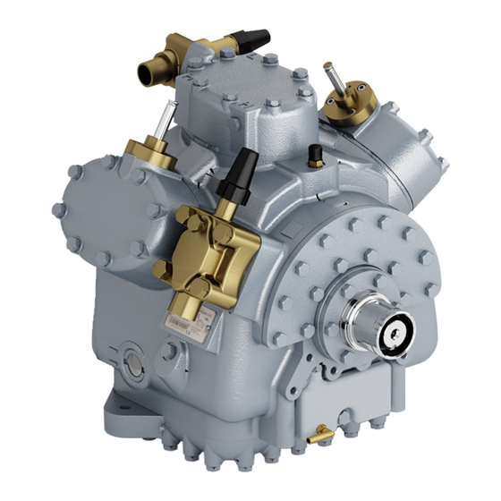
Page 6: Model 05G Compressor
REFRIGERATION COMPRESSOR (TRAILER) AIR CONDITIONING COMPRESSOR (BUS & RAIL) 1. Discharge Service Valve 6. Oil Level Sight Glass 2. High Pressure Connection 7. Bottom Plate 3. Low Pressure Connection 8. Oil Drain Plug 4. Suction Service Valve 9. Oil Pump (See Figure 1-3) 5. -
Page 7: Detailed Description
located in the bearing head assembly. The crankshaft is 1.4 DETAILED DESCRIPTION drilled to enable the pump to supply oil to the main 1.4.1 SUCTION AND DISCHARGE VALVES bearings, connecting rod bearings, and the shaft seal. The compressor uses reed type suction and discharge valves made of highest quality steel for long life. -
Page 8: Compressor Unloader
port is greater than the rate of bleed through the bleed 1.5 COMPRESSOR UNLOADER orifice (8). The 6 cylinder 05G compressor can be applied with 2 bank of unloading. When the pressure behind the piston has been reduced sufficiently, the valve spring will force the piston There are two types of compressor unloader systems;... -
Page 9: Compressor Cylinder Head Loaded
The loaded cylinder bank will continue to operate cylinders. No refrigerant is allowed into the cylinders and fully loaded until the solenoid valve control device is no compression takes place. energized and the gas bypass port is opened. SUCTION PRESSURE 1. -
Page 10: Compressor Cylinder Head (Loaded)
1. Sealing Cap SUCTION PRESSURE 2. Pressure Differential Adjustment Screw 3. Control Set Point Adjustment Nut DISCHARGE PRESSURE 4. Poppet Valve 1. Solenoid Valve 9. Suction Manifold 2. Coil 10. Suction Valve Figure 1-9. Pressure-Operated Unloader 3. Capacity Control 11. Piston Loaded Operation Valve (Closed) 12. -
Page 11: Compressor Replacement
SECTION 2 COMPRESSOR REPLACEMENT 2.1 COMPRESSOR REMOVAL 2.2.1 INSTALLING COMPRESSOR UNLOADERS Remove the three socket head capscrews Refer to the operation and service manual covering holding piston plug to cylinder head of the replacement the equipment in which the compressor is installed for compressor. -
Page 12: Oil Level In Sight Glass
Check oil level in sight glass (See Figure 2-2). If 2.2.2 INSTALLING COMPRESSOR necessary, add or remove oil. WARNING Leak test, evacuate, and dehydrate Midseat service valves or by other means relieve compressor. pressure in replacement compressor before removing plugs. Fully backseat suction and discharge service valves. -
Page 13: Compressor Maintenance
SECTION 3 COMPRESSOR MAINTENANCE 3.1 INTRODUCTION CYLINDER HEAD AND VALVE PLATE Prior to disassembly of the compressor, oil must first a. Disassembly be drained from the crankcase. Place the compressor in a WARNING position where it will be convenient to drain the oil. Do not unscrew capscrews all the way before Remove the oil fill plug to vent the crankcase. -
Page 14: Oil Pump And Bearing Head
Install suction valve positioning spring on dowel 3.4.1 LOW PROFILE GEAR PUMP pins. Assemble positioning spring springs with spring a. Removal ends bearing against cylinder deck. The spring will bow Remove eight capscrews and remove oil pump outward in the middle. (See Figure 3-2) bearing head assembly, gasket and thrust washer. -
Page 15: Gear Pump
c. Reassembly CAUTION Set screw on crankshaft must be removed for Low Profile Gear Pump (See Figure 3-4). Set screw on crankshaft must be removed for Low Profile Gear Pump. Install the pump end thrust washer on the two dowel pins located on the bearing head. (See Figure 3-4.) CAUTION Ensure that thrust washer does not fall off dowel pins while installing oil pump. -
Page 16: Vane Pump
c. Reassembly and spring guide. Insert retaining ring with ring pliers. Force the spring guide down to compress the plunger Install the pump end thrust washer on the two spring and to allow the retaining ring to fit into its locking dowel pins located on the bearing head. -
Page 17: Shaft Seal
Insert the oil feed guide with the large diameter b. Reassembly in. Insert the guide retaining spring so that it fits over the Install new shaft seal assembly, cover gasket, and smaller diameter of the feed guide. The pump cover can cover plate only. -
Page 18: Bottom Plate And Oil Strainer Removed
Push the piston rods down so that the piston loaded device which can be checked by using a small piece rings extend below the cylinders. Remove and discard of stiff wire to ensure that the spring can be depressed. piston rings. Use only new rings when reassembling the Remove piston rod assemblies. -
Page 19: Compressor Running Gear Reassembly
3.7 COMPRESSOR RUNNING GEAR CHAMFERED EDGE REASSEMBLY a. Seal End Main Bearings When installing new seal end main bearings the oil groove is on top of the compressor with V grooves pointing to each other. When installed, there must be a 5/16 inch (7.93 mm) gap between the two bearings (See Figure 3-14). -
Page 20: Suction Strainer
c. Crankshaft and Seal End Thrust Washer Check operation and reinstall check valves and relief valve. (See Figure 3-11). The check valves are Two brass thrust washers are used. The pump free-floating devices and can easily be checked visually. end thrust washer is positioned on two dowel pins located The relief valve is a spring-loaded device which can be on the bearing head and is installed with the oil pump and checked by using a small piece of stiff wire to ensure that... - Page 21 Table 3-1. Torque Values TORQUE RANGE TORQUE RANGE SIZE USAGE USAGE DIAMETER THREADS FT LB FT-LB (INCHES) PER INCH 1/16 27 (pipe) 8 to 12 1.11 to 1.66 Pipe Plug --- Crankshaft 27 (pipe) 15 to 20 2.07 to 2.77 Oil Return Check Valve --- Crankcase 20 (pipe) 20 to 25...
-
Page 22: Piston Dimension (Wear Limits)
Table 3-2. Wear Limits MAXIMUM WEAR MAXIMUM WEAR FACTORY MAXIMUM FACTORY MAXIMUM FACTORY MINIMUM FACTORY MINIMUM BEFORE REPAIR PART NAME PART NAME INCHES INCHES INCHES SEAL END End Play (Seal Removed) 0.035 0.8890 .030 0.7620 Main Bearing Diameter 1.8760 47.6504 .002 0.051 Main Bearing Journal Diameter... - Page 23 3-11...
Need help?
Do you have a question about the TRANSICOLD 05G and is the answer not in the manual?
Questions and answers