Advertisement
Quick Links
Advertisement

Summary of Contents for K&M KR200
- Page 1 KR200 SURFACE ROUGHNESS TESTER INSTRUCTION MANUAL K&M Instruments Ltd.
- Page 3 BRIEF INTRODUCTION ................. 13 1.1 M ................16 EASUREMENT RINCIPLE ..............18 TANDARD ONFIGURATION ..........20 AMES OF ART OF THE NSTRUMENT 1.4 B ................24 ASIC ONNECTION ETHOD 1.4.2 Installation and Removing of Pickup ........24 1.4.3 Power Adapter and Charging of Battery ........ 27 MEASURING OPERATION ................
- Page 4 ............30 REPARATION FOR EASUREMENT ..............34 ASIC EASUREMENT TATUS ........... 46 ODIFYING ONDITIONS OF EASUREMENT 2.3.1 Sampling Length ................47 2.3.2 Evaluation Length ................ 48 2.3.3 Standard ..................51 2.3.4 Range ....................53 2.3.5 Filter....................54...
- Page 5 2.3.6 Parameter ..................55 2.4 F ....................57 UNCTION ETUP 2.4.1. Switch to Print Mode/ to Data Mode ........59 2.4.2. Setting the Pair (PIN) Code ............60 2.4.3.Print Parameters ................... 62 2.4.4. Print Parameter and Profile ............64 2.4.5. Print Primary File .................
- Page 6 2.4.7. Calibration..................68 2.4.8. Time Setting .................. 71 2.4.9. Delete all data ..................73 2.4.10. Restore Factory Settings ..............73 2.5 System Setup .................... 73 2.5.1 Language ..................74 2.5.2 Unit....................75 2.5.3. LCD Back-light ................77...
- Page 7 2.5.4. LCD Contrast ................. 78 2.5.5. Bluetooth Power ................80 2.5.6. Printing Paper Width ..............81 2.6. PC ................83 ONNECTION WITH OPTIONS AND USAGE .................. 84 3.1A .......... 84 DJUSTABLE UPPORTER AND HEATH OF ICKUP 3.2. M ..................86 EASUREMENT TAND 3.3.
- Page 8 3.4.C ..........91 ONNECTION OD OF AGNETIC AUGE 3.5................. 93 URVED URFACE TECHNICAL PARAMETER AND FEATURES ..........95 4.1......................95 ICKUP 4.2.D ..................96 RIVING ARAMETER :L 4.3.D ±10% ........98 ISPLAY CCURACY ESS THAN OR EQUAL TO :L 4.4.D 6% ......
- Page 9 4.7 S L ..........101 AMPLING ENGTH AND OFF LENGTH 4.8 E ................101 VALUATION ENGTH LN 4.9 R .......... 102 OUGHNESS ARAMETER AND ISPLAY ANGE ~ 100% ......................104 4.10 M ............104 EASURING ANGE AND ESOLUTION 4.11 P ...................
- Page 10 4.14 C PC ..................108 ONNECT WITH 4.15 C ................108 ONNECT WITH RINTER GENERAL MAINTENANCE ................. 109 5.1.T ..................110 ROUBLE HOOTING 5.2.F ..................111 AULT NFORMATION BATTERY SWITCH ..................114 REFERENCE ....................117 7.1 P ..................117 ROFILE AND ILTER...
- Page 11 7.2. T ..................119 RAVELING ENGTH 7.2.1. RC filter ..................119 7.2.2. PC-RC filter .................. 120 7.2.3. .Gauss Filter ................121 7.2.4. D-P Direct Profile ................ 122 7.3 D PRSR200 R ......... 122 EFINITIONS OF OUGHNESS ARAMETERS 7.3.1. Arithmetical Mean Deviation of Profile ......... 123 7.3.2.
- Page 12 7.3.3. Rz Ten Point Height of Irregularities ........126 ( ) 7.3.4. Maximum Height of Profile ........128 7.3.5. Ry (DIN) Maximum Height of Profile........130 7.3.6. Rt Total Peak-to-valley Height..........130 7.3.7. Rp Maximum Depth of Profile Peak ........131 7.3.8.
- Page 13 7.3.11. Profile Bearing Length Ratio ........... 136 7.3.12. Skewness of the profile ............138 R3z Third Maximum Peak-to-valley Height ....... 139 7.3.13. ATTACHED TABLE:DISPLAY MAGNIFYING TIMES ......139...
-
Page 14: Brief Introduction
1 Brief Introduction KR-200 hand-held roughness tester is a new product developed by Time Group Inc. This tester applies to production site and can be used to measure surface roughness of various machinery-processed parts, calculate parameters according to selected measuring conditions and clearly display all measurement parameters and profile graphs on LCD. - Page 15 Features: Multi-parameter measuring:Ra, Rz, Ry, Rq, Rp, Rm, Rt, R3z, Rmax, Sk, S, Sm, tp; High accuracy inductance pickup; Four filtering methods of RC, PC-RC, GAUSS and D-P; Compatible with four standards of ISO, DIN, ANSI and JIS; 128×64 dot matrix LCD displays all parameters and graphs; DSP chip is used to control and process data with high speed...
- Page 16 and low power consumption; Built-in lithium ion chargeable battery and control circuit have high capacity, without memory effect. Consecutive work time is longer than 20 hours; Design of mechanical and electrical integration is adopted to achieve small bulk, light weight and easy usage;...
- Page 17 Can be connected to Bluetooth printer to print all parameters and graphs; Built-in standard USB interface enables communication with PC; Automatic switch off, memory and various prompt instructions; Accessories of curved surface pickup, measurement stand, sheath of pickup, adjustable supporter and extending rod are available. 1.1 Measurement Principle When measuring surface roughness of workpiece, the pickup is placed on the surface of the part and then tracing the surface at...
- Page 18 constant rate. The pickup acquires the surface roughness by the sharp stylus in pickup. The roughness causes displacement of pickup which results in change of inductive value of induction coils thus generate analogue signal which is in proportion to surface roughness at output end of phase-sensitive rectifier.
- Page 19 Standard Configuration Table 1-1Standard Configuration List Item Quantity...
- Page 20 Main Unit Standard Sensor Standard Sample plate Organic Glass Test Support Power Adapter Communication Cable Sheath of Pickup Height Adjustable Supporter...
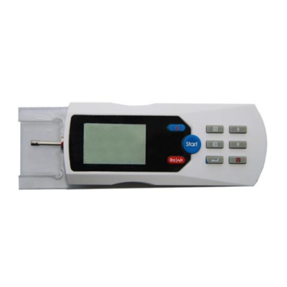
- Page 21 1.3 Names of Each Part of the Instrument...
- Page 22 Figure 1-1-1 Pickup...
- Page 24 Figure1-1-2 Front View ure 1-1-3 Side View...
- Page 25 Figure 1-1Names of Each Part of Instruments 1.4 Basic Connection Method 1.4.2 Installation and Removing of Pickup For installation, hold the main part of pickup with hand, push it into connection sheath at the bottom of the instrument as shown in Figure 1-2 and then slightly pushed it to the end of the sheath.
- Page 26 main part of pickup or the root of protective sheath with hand and slowly pull it out.
- Page 27 Figure 1-2 Installation of Pickup Tip: 1.The stylus of pickup is key part of this tester and great attention should be paid to it. 2.During installation and unloading, the stylus should not be touched in order to avoid damage and affecting measurement. 3.Connection of pickup should be reliable during installation.
- Page 28 1.4.3 Power Adapter and Charging of Battery When battery voltage is too low (that is, battery voltage symbol flashs on screen to prompt low voltage), the instrument should be charged as soon as possible. As shown in Figure 1-3, the plug of power adapter should be plugged into power socket of the instrument.
- Page 29 fulfilled at any time without affecting normal operation of the instrument Tip: 1. Layout of connection lines shall not affect measuring part under charging state. 2. Meanings of battery voltage prompts are: indicates normal voltage and measurement can be carried out; the black part inside prompt shows capacity of battery;...
- Page 30 The instrument will turn on automatically even it's turned off. 4. When the KR200 is delivered the battery switch is off, User should set the switch on firstly before use it. 5. When the instrument does not work properly, restart KR200 after...
-
Page 31: Measuring Operation
switching off the battery for 10 seconds 2 Measuring Operation Preparation for Measurement a.Switch-on to check if battery voltage is normal; b. Clear the surface of part to be measured; c. Refer to Figure 2-1 and Figure 2-2 to place the instrument correctly, stably and reliably on the surface to be measured;... -
Page 32: Front View
Figure 2-1 FRONT VIEW... -
Page 33: Side View
2-2 SIDE VIEW d. Refer to Figure 2-3, trace of the pickup must be vertical to the direction of process line of the measured surface. - Page 34 Figure 2-3 <Measuring Direction...
- Page 35 Instruction:Correct and standard operation is the premise for accurate measurement result, please make sure to follow it. Basic Measurement Status Press and release Power key to switch on. The instrument automatically displays model, nameand information manufacturer, and then enters basic measurement status, as shown in Figure 2-4.
- Page 38 Figure 2-4 Boot Process Instruction: 1. Contents of basic measurement status entered in the first switch-on are factory settings of this instrument. Settings and data of last switch-off will be displayed in the next switch-on. Basic measurement status will be entered automatically for each switch-on (as shown in Figure 2-4).
- Page 39 In basic measurement status, the follows can be performed: ◆ Measurement Sta rt Press Start key to start measurement,as shown in Figure 2-5.
- Page 40 Figure 2-5 Measuring Process ◆ Enter menu operation status...
- Page 41 Press Menu key to enter menu operation status. For detailed operation, see descriptions in corresponding chapters and sections later. ◆ Display measurement parameters Press Parameter key first to shows all parameter values of this measurement. Press Scroll key to scroll pages; secondly, press Parameter key to displays profile graphs of...
- Page 42 this measurement. Press Scroll key to roll profile graphs with other sampling lengths; thirdly, press Parameter key to displays tp curve and tp value of this measurement; Press the keys again will repeat above descriptions. Press Esc key in each status to return basic measurement status (as shown in figure below).
- Page 43 0.031 0.035 0.027 0.072 0.120 0.064 LTH: 0.25*5mm STD:ISO 0.008 + - 20um FIL:RC RAN: 0.0089 l:1 Vv:5 0.2083 1.207 l:2 Vv:5 l:3 Vv:5 l:4 Vv:5 l:5 Vv:5 c(%Ry) tp(%) (%Ry) c(%Ry) tp(%) 78.7 78.7 99.6 99.6 99.6 FIGURE 2-6 Display of Parameters...
- Page 44 ◆ Display position of stylus Press Enter key to show the position of stylus in shortcut mode, which is easy to use in practical measurement. Figure 2-7 Postion of Stylus...
- Page 45 Instruction: 1. Tester automatically stores results and conditions of last measurement beforeit is turned off, and will automatically enter this status while it is turned on again. Sta rt 2 After entering basic measurement status, press Start key measure, if measuring conditions are not needed to be changed.
- Page 46 instructions Preparation Measurement (adjustment is not needed generally). key to display profile , press 4. When press can change , magnifying times which 1× 2× 5× 10× 20× 50× and display circularly.
- Page 47 Modifying Conditions of Measurement Under basic measurement status, press Menu key to enter menu operation status. Press Scroll key to select setting function of measured conditions, and then press Enter key to enter Set Measurement Conditions status. In this status, all measurement conditions can be modified (as shown in Figure 2-8).
- Page 48 Figure 2-8 2.3.1 Sampling Length After entered setting status, press Scroll key select Set Sampling Length. Press Enter key to cycle with 0.8 mm →2.5mm →auto→0.25mm (as shown in Figure 2-8). Stop at the value you want and press Scroll key...
- Page 49 modify others. 2.3.2 Evaluation Length Press Menu key to enter menu operation status and press Scroll key to select Set Measurement Conditions. Press Enter key to enter Set Measurement and press Scroll key...
- Page 50 to select Set n*cutoff. Press Enter key cycle with 1L→2L→3L→4L→5L (as shown in Figure 2-9) Stop at the value you want and press Scroll key to modify others. Figure 2-9...
- Page 51 Instruction: When sampling length is set to be automatic, evaluation length will automatically display value 5 to match. This value can not be modified.
- Page 52 2.3.3 Standard Press Menu key to enter menu operation status and press Scroll key to select Set Measurement Condition. Press Enter key for measurement setting and press Scroll to select Set Standard. Press Enter key ISO DIN JIS ANSI. to cycle with...
- Page 53 Table 2 Standard Code and Name Code Standard Name ISO 4287 International Standard DIN 4768 Germany Standard JIS B601 Japan Industrial Standard ASME B46.1 USA Standard...
- Page 54 2.3.4 Range Press Menu key to enter menu operation status and press Scroll key to select Set Measurement Conditions. Press Enter key for measurement setting and press Scroll to select Set Range. Press Enter key ±20µm ±40µm ±80µm → → →...
- Page 55 2.3.5 Filter Press Menu key to enter menu operation status and press Scroll key to select Set Measurement Conditions. Press Enter key for measurement setting and press Scroll...
- Page 56 to select Set Filter. Press Enter key cycle with RCPC-RCGaussD-P. 2.3.6 Parameter Press Menu key to enter menu operation status and press...
- Page 57 Scroll key to select Set Measurement Conditions. Press Enter key for measurement setting and press Scroll to select Parameter. Press Enter key cycle with Ra → Rz → Ry → Rq (of which: five parameters of RaRzRyRmax Rq are available for ANSI[American Standard] and DIN[German Standard]).
- Page 58 Function Setup Press Menu key to enter menu operation status and press Scroll key to select Function Setup. Press Enter for function setting.In function Setup (as shown in...
- Page 59 Figure 2-14), modify contents of system settings. Figure 2-14...
- Page 60 2.4.1. Switch to Print Mode/ to Data Mode Via built-in bluetooth module, KR200 can realize wireless printing and data transferring with PC, mobile etc. These two functions are realized in different modes by bluetooth module, hence function switch off is needed. If the current mode is digital mode, the menu display “to PRT (PRINT)
- Page 61 2.4.2. Setting the Pair (PIN) Code Setting the pair code is to enhance the applicability of roughness tester for Bluetooth printer, and to avoid the limitation of Bluetooth printer manufacture.
- Page 62 Press the menu key to enter menu operation and press the scroll key to choose function setup. Press the enter key to enter function setup and press the scroll key enter set print pin function. Press the enter key to the interface of set print pin.Press the enter key to choose the different No.
- Page 63 2.4.3.Print Parameters Press Menu key to enter menu operation status and press Scroll key to choose Function Selection. Press Enter...
- Page 64 to enter Function Selection status and press Scroll key to select Print Parameter. Press Enter key print all measurement parameters (as shown in Figure 2-19).
- Page 65 2.4.4. Print Parameter and Profile Press Menu key to enter menu operation status and press Scroll key to choose Function Selection. Press Enter to enter Function Selection status and press Scroll key to select Print Parameter and Profile. Press Enter to start printing.
- Page 66 figure. 2.4.5. Print Primary File Press Menu key to enter menu operation status and...
- Page 67 press Scroll key to choose Function Selection. Press Enter key to enter Function Selection status and press Scroll key to select Primary Profile. Press Enter key to display Primary Profile (i.e. Direct Profile or Original Profile) in this measurement on LCD.
- Page 68 2.4.6. Stylus Position Press Menu key to enter menu operation status and press Scroll key to choose Function Selection. Press Enter to enter Function Selection status and press Scroll key to select Stylus Position. Press Enter key display the Stylus position.
- Page 69 2.4.7. Calibration Press Menu key to enter menu operation status and press Scroll key to choose Function Selection. Press Enter to enter Function Selection status and press Scroll key...
- Page 70 to select Display Value Calibration function. Press Enter key to enter Calibration status and press Scroll key to change calibration coefficients. Press Enter key to move cursor.
- Page 71 Instruction: 1. While using correct measuring method to test random sampling plate, if measured value exceeds ±10% of the value of sampling plate, use Display Value Calibration function to calibrate according to the percentage of real deviation with calibration range within ±20%.
- Page 72 2. Generally, instrument has been strictly tested before delivery so as to ensure display value error to be much less than ±10%. In this case, user is suggested not to frequently use Display Value Calibration function. 2.4.8. Time Setting Press enter key to enter into menu operation,...
- Page 73 to choose RTC Setup,press the enter key to enter into TIME SETTING Press the scroll key to change the No. under the cursor ,press the enter key to Move cursor circularly.
- Page 74 2.4.9. Delete all data 2.4.10. Restore Factory Settings 2.5 System Setup Press Menu key to enter menu operation status and press Scroll key to select System Setup. Press Enter key for system setting.In System Setup (as shown in Figure...
- Page 75 2-14), modify contents of system settings. 2.5.1 Language Press Menu key to enter menu operation status and press Scroll key to select System Setup. Press Enter key for system setting and press Scroll key select Language. Press Enter key for language selection...
- Page 76 and press to select the language you want. Press Enter key to confirm. 2.5.2 Unit Press Menu key to enter menu operation status and press...
- Page 77 Scroll key to select System Setup. Press Enter key for system setting andpress Scroll key choose Unit. Press Enter key to switch between metric system and British system.
- Page 78 2.5.3. LCD Back-light Press Menu key to enter menu operation status and press Scroll key to select System Setup. Press Enter for system setting and press Scroll key select LCD Back-light On/Off. Press Enter key to switch between On and Off.
- Page 79 Tip:Press after turn on the TR200 for back-light. 2.5.4. LCD Contrast Press Menu key to enter menu operation status and press Scroll key to select System Setup. Press Enter key...
- Page 80 for system setting and press Scroll key LCD Brightness Adjustment. Press Enter key to enter LCD Brightness Adjustment and press Scroll key adjust the brightness to satisfactory degree.
- Page 81 2.5.5. Bluetooth Power to enter menu operation , then Press menu key press to choose System Setup, press to enter, press to choose Bluetooth,press to display ON and OFF circularly. This menu is mainly on occasion to some does not require the...
- Page 82 use of Bluetooth module , which can reduce the power consumption. 2.5.6. Printing Paper Width The Bluetooth module of the roughness tester can drive a Bluetooth printer to print testing report, in order to enhance the adaptability of the...
- Page 83 Two kinds of printing paper can be choosed : 57mm and 80m. These 2 types of printers can be worked with KR200 perfectly! Press menu key to enter menu operation status and press scroll key to choose System Setup . Press enter...
-
Page 84: Connection With Pc
show 57mm、80mm circularly. 2.6. Connection with PC Before communicating with PC, connect the instrument to serial interface of PC with communication cable attached to the instrument as shown in Figure, and enter private operation software Data View on PC. -
Page 85: Options And Usage
3.1Adjustable Supporter and Sheath of Pickup When measured surface of part is smaller than the bottom surface of the instrument, sheath of pickup and adjustable supporter of KR200 options can be used for auxiliary support to complete the measurement (as shown... - Page 86 Figure 3-1Usage of Adjustable supporter and Sheath of Pickup...
- Page 87 Tip:1.L above shall not be shorter than driving stroke of this measurement to prevent pickupfrom dropping out of part during measurement. 2. Locking of adjustable supporter shall be reliable. 3.2. Measurement Stand PT series measurement Stand can adjust the positions between tester and measured part conveniently with flexible and stable operation and wider application range.
- Page 88 If Ra value of measured surface is relatively low, Using measurement platform is recommended.
- Page 89 Figure 3-2 Testing Platform...
- Page 90 3.3. Extending Rod Extending rod increases the depth for pickup to enter the workpiece. Length of extending rod is 50mm.
- Page 91 Figure 3-3 Extension Rod...
- Page 92 3.4.Connection Rod of Magnetic Gauge Base Connection rod connects the tester with magnetic gauge base so as to measure various surfaces of parts flexibly and easily as shown in figure 3-5. It's particularly suitable for production sites.
- Page 93 Figure 3-5 Test Stand connect with Magnetic Base...
- Page 94 3.5. Curved Surface Pick Up Curved surface pickup can measure convex or concave surfaces of parts, as shown in the figure below.
- Page 95 Figure 3-7 Curved Surface Pick up...
-
Page 96: Technical Parameter And Features
4. Technical Parameter and Features 4.1. Pickup Test Principle:Inductance type MeasurementRange: 160μm Stylus tip Radius:5μm Stylus tip Material:Diamond Measuring force : 4mN(0.4gf) - Page 97 Stylus tip Angle: 90° Radius of Skid curvature:45mm 4.2.Driving Parameter Maximum drive range: 17.5mm/0.7inch Traversing speed: measuring...
- Page 98 sampling length = 0.25mm Vt=0.135mm/s sampling length = 0.8mm Vt=0.5mm/s sampling length = 2.5mm Vt=1mm/s returning V=1mm/s...
- Page 99 4.3.Display Accuracy:Less than or equal to ±10% : 4.4.Display Repeatability Less than or equal to 6% 4.5. Display Content 4.5.1 Menu: modify measurement conditions, calibration display value and select communication with PC or printing. 4.5.2 Parameter: parameters of roughness compatible with four standards of ISO, DIN, ANSI and JIS.
- Page 100 4.5.3 Graph: Primary profile, filtered profile and tp curve. 4.5.4 Prompt information: measurement, menu prompt, errors, battery capacity and switch-off prompt information. 4.6. Profile and Filter Table 3 Profile Filter...
- Page 101 PC-RC Gauss Filtered Profile Non-Filtered Profile...
- Page 102 4.7 Sampling Length and Cut-off length L Automatic,0.25mm,0.8mm,2.5mm are selectable 4.8 Evaluation Length ln (1~ 5)l*Sampling Length is selectable...
- Page 103 4.9 Roughness Parameter and Display Range Table 4 Parameter Display Range 0.005μm ~ 16μm...
- Page 104 0.02μm ~ 160μm 0 ~ 100%...
- Page 105 ~ 100% 4.10 Measuring Range and Resolution Table 5 Measuring Range Resolution 0.01μm ~0.04μm Automatic...
- Page 106 ±20μm 0.01μm ±40μm 0.02μm ±80μm 0.04μm 4.11 Power Supply AC adapter: Rating: 6V, 500mA Supply voltage: 220V...
- Page 107 Built-in battery(Lithium ion battery): Charging time: 2.5 hours Consecutive work time per charge: more than 20 hours Auto-sleep function: display turns off if not operated for 5 minutes 4.12 Temperature/Humidity Range Working environment: Temperature: 0 ~ 40℃...
- Page 108 Humidity:< 90% RH Store and transportation: Temperature:-40℃~ 60℃ Humidity: < 90% RH 4.13Dimension and Weight L×W×H: 140×52×48mm, Mass: approximately 440g...
- Page 109 4.14 Connect with PC MINI USB cable 4.15 Connect with Printer Connect with PT210-BT bluetooth series printers, . TA210 printer only prints parameters. TA220s can print parameters as well as profile figures.
-
Page 110: General Maintenance
5. General Maintenance Avoid crash, intensive vibration, heavy dust, humidity, grease stain and strong magnetic field; Pickup is a precise part and should be protected carefully. Put it back in the package box after operation of each time; ... - Page 111 5.1.Trouble Shooting When the tester breaks down, handle the troubles according to measures described in next section Fault Information. If troubles still exist, please return the instrument to factory for repair. Users should not dismantle and repair the device by themselves. Returned instrument should be accompanied with warranty card and sample plate attached.
- Page 112 5.2.Fault Information Table 6 Display Cause Solutions Content 1. Press Esc key to return; Maximum value of 2. Enter menu setting status, measured signal Out of Range increase measuring range, exceeds press Esc key to return; measuring range; 3. Measure again.
- Page 113 1. Press Esc key to return; Wrong operation 2. Check preparation results in failed No data measuring is correct; measuring; 3. Switch measure again. Scheme 1: Switch off and switch on again; Hardware circuit Scheme 2: Press Reset key; fault; A/D failure Scheme 3: Return to factory to repair.
- Page 114 Scheme 1: Switch off and switch on again; : Mechanical fault; Scheme 2: Press Reset key; Motor failure Scheme 3: Return to factory to repair. Pickup 1. Press Esc key to return and automatic return wait till pickup returns to the Pickup failure process start position;...
-
Page 115: Battery Switch
Working Turnoff and then restart abnormally switch the battery off, then switch the battery on 10 seconds later. 6. Battery Switch The battery switch is at the bottom of the instrument as shown in Figure 6-1. - Page 116 Figure 6-1 Power ON and OFF 1. When charging, the battery switch must be in the ON position, or can not be charged.
- Page 117 Suggesting make a backup before switching off the battery. 3. When the instrument is delivered from manufacture, the switch off is in the OFF position, press the POWER key to turn on if KR200 dose not work after switching on.
- Page 118 7. Reference 7.1 Profile and Filter 7.1.1 Profile a. primary profile: non-filtered profile signal obtained by pickup from measured surface. b. Filtered profile: profile signal after primary profile is filtered to remove waviness...
- Page 119 7.1.2 Filter a. RC filter: analogue 2RC filter with phase difference; b. PC-RC filter: RC filter with phase-correction; c. Gauss filter: DIN4777 d. D-P (direct-profile): adopt central line of Least Square Algorithm.
- Page 120 7.2. Traveling Length 7.2.1. RC filter Traversing Length...
- Page 121 7.2.2. PC-RC filter Traversing Length...
- Page 122 7.2.3. .Gauss Filter l /2 l /2 Traversing Length...
- Page 123 7.2.4. D-P Direct Profile Traversing Length 7.3 Definitions of KR200 Roughness Parameters This section gives definitions of KR200 measurement parameters.
- Page 124 7.3.1. Arithmetical Mean Deviation of Profile Ra is arithmetic mean of the absolute values of profile deviation (Yi) from mean within sampling length. ...
- Page 126 7.3.2. Rq Root-mean-square Deviation of Profile Rq is the square root of the arithmetic mean of the squares of profile deviation (Yi) from mean within sampling length. ...
- Page 127 7.3.3. Rz Ten Point Height of Irregularities The sum of the mean height of the five highest profile peaks and the mean depth of the five deepest profile valley from mean within the sampling length. ...
- Page 129 7.3.4. Ry(ISO)Maximum Height of Profile Ry is The sum of height Rp of the highest profile peak from the mean line and depth Rv of the deepest profile valley from the mean line within sampling length.
- Page 131 7.3.5. Ry (DIN) Maximum Height of Profile To get Ry (DIN) value: firstly calculate Ryi in each sampling length, the maximum of which is the Ry (DIN) for the evaluation length. 7.3.6. Rt Total Peak-to-valley Height Rt is the sum of the height of the highest peak and the depth of the deepest valley over the evaluation length.
- Page 132 7.3.7. Rp Maximum Depth of Profile Peak Rp is the height from the highest profile peak line to mean line within sampling length. 7.3.8. Rm Maximum Depth of Profile Valley Rm is the depth from the deepest profile valley line to mean line within sampling length.
- Page 133 7.3.9. Sm Mean Spacing of Profile elements Sm is the mean spacing between profile peaks at the mean line within sampling length. ...
- Page 135 7.3.10. S Mean Spacing of Local Peaks of Profile S is the mean spacing of adjacent local peaks of the profile within sampling length. ...
- Page 137 7.3.11. Profile Bearing Length Ratio The bearing ratio tp is the length of bearing profile ,at a depth c below the highest peak. Tp(%) is the ratio at the depth c. ...
- Page 138 ...
- Page 139 7.3.12. Skewness of the profile Sk is the quotient of the mean cube value of the profile deviation (Yi) and the cube of Rq within sampling length.
- Page 140 7.3.13. R3zThird Maximum Peak-to-valley Height is the mean of the sum of the third profile peak height and the third profile valley depth of each sampling length over evaluation length. 8. AttachedTable:DISPLAY MAGNIFYING TIMES Following is the table of comparison between Display Magnification...
- Page 141 Times and Screen Display Full Range. Double magnification, showed that the range is narrowed down one times. Adjustment by pressing Magnification times ×1 ×2 ×5 10× 20× 50×...
- Page 142 Range Displaying /range ±20µm ±20µm ±10µm ±4µm ±2µm ±1µm ±0.4µm ±40µm ±40µm ±20µm ±8µm ±4µm ±2µm ±0.8µm ±80µm ±80µm ±40µm ±16µm ±8µm ±4µm ±1.6µm...
Need help?
Do you have a question about the KR200 and is the answer not in the manual?
Questions and answers