Table of Contents
Advertisement
Quick Links
Advertisement
Table of Contents

Related Manuals for FRITERM FDH

Summary of Contents for FRITERM FDH
- Page 1 Adiabatic Cooling Systems INSTALLATION, OPERATION AND INSTALLATION, OPERATION AND INSTALLATION, OPERATION AND INSTALLATION, OPERATION AND MAINTENANCE INSTRUCTIONS MAINTENANCE INSTRUCTIONS MAINTENANCE INSTRUCTIONS MAINTENANCE INSTRUCTIONS www.friterm.com...
-
Page 2: Table Of Contents
İÇİNDEKİLER 1. ABOUT THIS MANUAL/ GENERAL ....................3 1.1 Examining the operating manual ......................3 1.2 Responsibilities ............................3 1.2.1 Manufacturer’s Responsibilities ..................... 3 1.2.2 Contractor’s Responsibilities (Installation, Commissioning) ............4 1.2.3 Operator’s or Owner’s Responsibilities (Operation and Maintenance) ......... 4 1.3 Warranty .............................. - Page 3 5.2.5Horizontal types set up next to wall ....................21 6. COMPONENTS OF ADIABATIC COOLING SYSTEM ..............22 6.1 Water Spraying System ........................22 6.1.1 Fitting group ..........................23 6.1.2 Nozzles ............................23 6.1.3 Water spraying pipes ........................25 6.2 Meshes ..............................25 6.3 Cooling Pad ............................
-
Page 4: About This Manual/ General
1. ABOUT THIS MANUAL/ GENERAL This document specifies the instructions for installation, operating and maintenance of the products which have water spry system (FDH, FDV, FDW, FCH, FCV, FCW, NCH and NCV models) manufactured by FRITERM A.Ş., Turkey. The instructions below must be followed strictly for the labor health and safety reasons during installation and maintenance of products. -
Page 5: Contractor's Responsibilities (Installation, Commissioning)
The national regulations regarding the protection of environment and labor safety should be • strictly followed besides the instructions for safe and correct operation. In case of any problem encountered during the installation, FRITERM A.Ş. should be • informed and asked for technical assistance if necessary. -
Page 6: Warranty
Any defect/damage/malfunction caused by the misuse of the product is the responsibility of • the operator. The product should not be put in operation without the completion of the installation and • commissioning. The personnel who is responsible for the operation/servicing/maintenance of the product •... -
Page 7: Safety Regulations
product should installed commissioned accordance with • national/international regulations and rules. For the fans having thermal protection, the related wiring should be definitely done and it is • considered as contractor’s and/or owners’ responsibility. Any defect caused by misconnection of the thermal protection wiring in accordance to the circuit diagrams given in this manual would be out of manufacturer’s warranty. -
Page 8: Personal Protection
IN CASE OF DANGER IN CASE OF DANGER! Switch off the power • Switch off the main • Please ask assistance from an authorized Please ask assistance from an authorized technician or expert. • Please do not try to resolve any problem by trial and error. Please do not try to resolve any problem by trial and error. -
Page 9: Warning Signs
Protective Clothing Protective Clothing Hand Protection Respiratory Protection Respiratory Protection 2.2.2 Warning signs No SmokingFlammable No SmokingFlammable High Voltage High Voltage Hot Surfaces Hot Surfaces Hand Injuries Hand Injuries Poisoning Danger Poisoning Danger Fire Risk Fire Risk Frostbite Hazard Frostbite Hazard 2.3 Warnings In an unexpected situation use the emergency stop button which is set up on an easily unexpected situation use the emergency stop button which is set up on an easily... -
Page 10: Improper Use
FRITERM A.Ş. 2.4 Improper Use Danger of injuries in improper using;... -
Page 11: Hazardous Thermal
AY SYSTEM DEFINITION 3 types of adiabatic cooling systems 3 types of adiabatic cooling systems can be applied to dry coolers and condenser of dry coolers and condenser of Friterm A.Ş; direct,ecomesh and cool pad adiabatic cooling systems adiabatic cooling systems. - Page 12 Water spray provides an adiabatic cooling effect of till 25 ° C for the incoming air stream and it can be initiated via an ambient sensor or alternatively by external control override. As soon as settings exceed, a pre-set level controller initiates water spray in order to make air temperature lower during high ambient periods.
- Page 13 Picture 1- Ecomesh water spray system at vertical type condensers Picture 2- Ecomesh water spray system at V type Picture 3-Ecomesh water spray system at horizontal type condensers condensers Picture 5-Ecomesh water spray system at horizontal type Picture 4- Ecomesh water spray system at V type dry coolers dry coolers Rev.
-
Page 14: Direct Adiabatic Water Spray System
3.2 Direct Adiabatic Water Spray System Directadiabatic water spray system comprises a series of specialized water nozzles fitted intermittently. The nozzles are designed to pulverize the water and provide a very fine mist of atomized water droplets which are readily absorbed by the high temperature ambient air approaching the coil. -
Page 15: Adiabatic Cooling Pad System
Picture 7-V type dry cooler with direct spraying system 3.3Adiabatic Cooling Pad System In adiabatic cooling pad systems, coolpads are placed in special sheet metal assemblies which are mounted in front of fin block. With the aid of the pump, water wets the pads from the upper part of the pad system. -
Page 16: Recirculated Adiabatic Cooling Pad System
System can be built in two ways as recirculated and uncirculated. 3.3.1. Recirculated Adiabatic Cooling Pad System In recirculated adiabatic systems, water that flow over the pads, collected at the drain pan. When it reaches a certain level, it is pumped back to the upper part water spraying line by the circulation pump. -
Page 17: Transport And Storage
Picture 8- V Type dry cooler with adiabatic cool pad system 4. TRANSPORT AND STORAGE 4.1 Check for completeness and transport damage Attention! May cause severe injuries or unrecoverable damages in case of uncontrolled • fall down. Instructions on lift and transportation should be strictly followed. •... -
Page 18: Installation
Suitable transport equipment must be used. 5. INSTALLATION The system installer is responsible for the proper installation according to standards and guidelines (DIN EN 292 / 294) which contains installation and security guidelines. Before installing, it must be ensured that the technical specifications of the product are in accordance with the desired working conditions. -
Page 19: Requirements At The Set Up Point
5.2 Requirements at the set up point 5.2.1 Horizontal types set up side by side 5.2.2 Vertical types set up next to wall Smin ≥ H Rev. Tarihi:20.09.2017 Rev.No:1 Dok. No: KLV.008.ENG... -
Page 20: Vertical Types Set Up In Pit-Hallow
5.2.3 Vertical types set up in pit-hallow Rev. Tarihi:20.09.2017 Rev.No:1 Dok. No: KLV.008.ENG... -
Page 21: 4Horizontal Types Set Up In Pit-Hallow
5.2.4Horizontal types set up in pit-hallow ≥ 0,5 ∗ = 450 − 600 mm Rev. Tarihi:20.09.2017 Rev.No:1 Dok. No: KLV.008.ENG... -
Page 22: 5Horizontal Types Set Up Next To Wall
5.2.5Horizontal types set up next to wall To avoid bypassing of the blowing air due to the side wall, a blocking accessory should be used. Also a dry-cooler half-width lifting case or higher feet should be used to facilitate the suction from down side. -
Page 23: Components Of Adiabatic Cooling System
6. COMPONENTS OF ADIABATIC COOLING SYSTEM Adiabatic cooling systems comprises of the following equipment; Water spraying system 2) Meshes (for ecomesh systems) 3)Cool pads (for cool pad systems) Fittings, tighten elements and system installation Controller and electric connection Quick change type plastic nozzles connected in series and parallel arrangement in order to provide uniform coverage area for an effective evaporation process. -
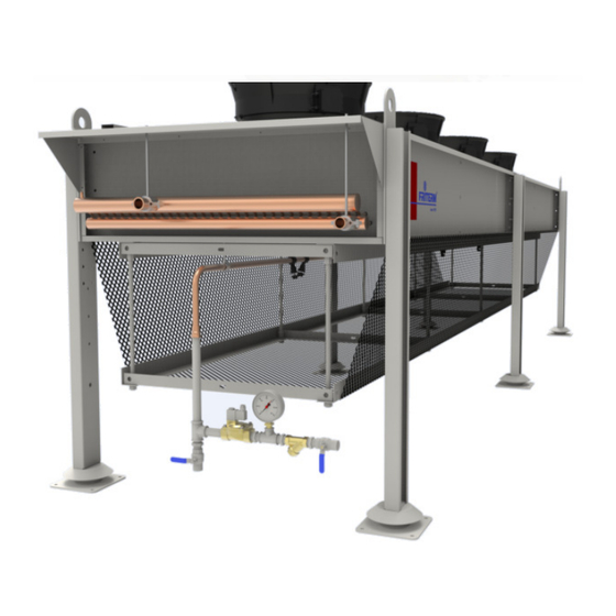
Page 24: Fitting Group
6.1.1 Fitting group The fitting group is provided to the customer as a whole fitted together. It comprises nipple, solenoid valve, hydrometer, water strainer and globe valve. Selenoid Valve Hydrometer Spraying line Globe valve Water inlet line Water Filter At the entrance of the installation there is a water filter. There is also a wire filter inside the nozzle to avoid dirt. - Page 25 Nozzles should be mounted approximately the angle of 45° as shown above. The nozzles should be placed in a way that the water will be sprayed widely and equally to the meshes. For direct spraying systems the distance between nozzles and fins should be 400- 600 mm. Picture 10- Nozzles mounting angle Rev.
-
Page 26: Water Spraying Pipes
6.1.3 Water spraying pipes Water spraying pipes are sent to the customer with the unit. It is mounted to the mounting holes on the product with the help of the clamps. Extra loading on the piping system may cause leakage on the piping. 6.2Meshes Nonmetallic mesh provides an effective coverage area for an efficient evaporation surface with minimal air pressure drop. -
Page 27: Cooling Pad
The dust on the meshes should be cleaned with pressurized air or water at least once in a week. 6.3 Cooling Pad Cellulosic Media Pad It is a cellulosic paper impregnated with chemicals that provide easy wettability and durability. The wavy and cross-channel structure expands the surface area, facilitating air to water contact and minimizing air resistance. -
Page 28: Installation For Vertical And Horizontal Type Units
6.4.1Installation for vertical and horizontal type units The installation pipes on which the nozzles are mounted, are mounted with the clamps to the plate. Once the installation pipes have been installed in place, the clamping assembly is fastened with M8 bolts to the nut rivets previously punched. - Page 29 Then the fitting group is installed at the end of the installation pipe. The mesh is attached to the special rails on the product with the clips sent alongside the product. (For ecomesh installation) Rev. Tarihi:20.09.2017 Rev.No:1 Dok. No: KLV.008.ENG...
-
Page 30: Installation For V Type Units
After all the meshes are mounted, the tensioning devices are set and fixed. (For network connection) 6.4.2Installation for V type units 6.4.2.1 Installation of ecomesh system First, the mesh tensioning assembly is connected to the mounting holes on the unit with M16 studs. - Page 31 The straight pipe on which the spraying nozzles are located arefitted with the clamps connected to the net tensioning device. After the straight pipe installation is completed on both sides, the U pipe connecting both pipes is installed. Rev.
- Page 32 The fitting group installed to the end of the U pipe. The mesh is attached to the special rails on the product with the clips sent alongside the product. Rev. Tarihi:20.09.2017 Rev.No:1 Dok. No: KLV.008.ENG...
- Page 33 After all the meshes are mounted, the tensioning devices are set and fixed. (For network connection) 6.4.2.2 Installation of direct spraying system First of all, the installation support sheet is mounted on the mirrors shown in the technical drawing.
- Page 34 Then the flat installation pipes are attached to the clamps and mounted on the product. After the installation of the flat pipes, the installation of the U pipe connecting these pipes is carried out. Rev. Tarihi:20.09.2017 Rev.No:1 Dok. No: KLV.008.ENG...
- Page 35 Finally, fitting group is installed at the end of the U pipe. Rev. Tarihi:20.09.2017 Rev.No:1 Dok. No: KLV.008.ENG...
- Page 36 6.4.2.3 Adiabatic cooling pad system installation cooling pad system installation In the standard assembly of the unit, firstly, the side cover plates which are prepared with In the standard assembly of the unit, firstly, the side cover plates which are prepared with In the standard assembly of the unit, firstly, the side cover plates which are prepared with the necessary fasteners fasteners are mounted.
- Page 37 Then the bottom cover plates are mounted. Then the bottom cover plates are mounted. Pre-assembled cooling pad modules are mounted on the nuts on the side cover plates. assembled cooling pad modules are mounted on the nuts on the side cover plates. assembled cooling pad modules are mounted on the nuts on the side cover plates.
- Page 38 After the assembly of the sheet metals the assembly of the sheet metals is completed, the cooling pads can be placed. The is completed, the cooling pads can be placed. The pads are pushed in from the outside as shown below, until they reach the upright position. pushed in from the outside as shown below, until they reach the upright position.
- Page 39 After the assembly of the pad modules is completed, After the assembly of the pad modules is completed, is the system is recirculated system, is the system is recirculated system, the pump system is assembled. The coarse partic the pump system is assembled. The coarse particle filter must be installed before the le filter must be installed before the pump is installed.
- Page 40 After the pump installation is done , the After the pump installation is done , the PVC pipe which connects the two cooling pad the two cooling pad modules, is mounted between two drainage outlets. is mounted between two drainage outlets. ...
- Page 41 The system feed is made from the nipple input shown below. The system feed is made from the nipple input shown below. Rev. Tarihi:20.09.2017 Rev.No:1 Rev.No:1 Dok. No: KLV.008.ENG Dok. No: KLV.008.ENG...
-
Page 42: Controller And Electric Connection
6.4Controller and Electric connection 6.4.1Direct adiabatic water spray system controller The system is controlled by a thermostat. The stepped thermostat on the product controls the cut- in and cut-out of the fans and it commands in an integrated manner to the turn on/off of the solenoid valve. -
Page 43: Controller Working Principle And Definition
Picture 11- Ecomesh Controller 6.4.3 Controller Working Principle and Definition Rev. Tarihi:20.09.2017 Rev.No:1 Dok. No: KLV.008.ENG... -
Page 44: Electric Connection System
Picture 12- Ecomesh Controller Working Principle and Definition 6.4.4Electric connection system Ecomesh Temperature AND Time Controller Block Diagram The operator panel consists of two Printed Circuit Boards (PCB) which house the power supply, sensor input conditioning circuitry, microcontroller, 7-segment Light Emitting diode (LED) display for temperature and timer indication, status indicating LED, control and setting push buttons, and output circuitry. - Page 45 Power supply The control panel requires 110 or 240Vac 5VA max. 50/60Hz supply. Please specify the supply voltage when order. Sensor input A platinum resistance thermometer PT100 temperature sensor is supplied as standard. External override input An optional volt-free contact can be connected to the external override input to force the controller output to maximum when the contact is closed.
-
Page 46: Adiabatic Cooling Pad System Controller
Picture 13- Electric connection diagram 6.5.5 Adiabatic cooling pad system controller The control device (thermostat) adjusted according to the applied system goes into operation with the operation of the domestic line pump if the ambient conditions rise above the set values. Water is conveyed from the top through the cooling pads, with the aid of the pump. -
Page 47: Operation
7. OPERATION All the parameters in the Ecomesh controller can be accessed by pressing the scroll button. Apart from the measured temperature, all the parameters can be set within their limits using the UP and DOWN button.The following are the list of parameters: ECOMESH CONTROLLER SETTING DESCRIPTION Initial factory setup Controller... -
Page 48: Spraying System Water Characteristics
Ecomesh water spray system controller can be operated in 3 different conditions. 1) "t" Ambient temperature is between L (Minimum temperature) and H (Maximum temperature) 2) "t" Ambient temperature is above H (Maximum temperature) and 3) Independent of temperature The detailed information are given below table. ECOMESH KONTROLLER WORKING CONDITIONS 1.Condition: 2.Condition:... -
Page 49: Initial Commissioning
7.1 Initial commissioning Initial commissioning Before running the unit for the first time, the following facts should be checked. Before running the unit for the first time, the following facts should be checked. Before running the unit for the first time, the following facts should be checked. 1. -
Page 50: Shutting Down
Electrical <100 µS/ cm conductivity 2< x< 5° fH (50 ppm Total hardness CaCO3) 6.5<pH<8.5 Chloride content < 20 mg/l Silica content < 5 mg/ l Demineralized or osmos water is not required. 7.3 Shutting down To close the water sprinkler system completely, the electrical connection must be cut off and the fluid circulation pump in the system must be switched off. -
Page 51: Periodical Controls (Once A Year)
8.3 Periodical Controls (Once a year) Check the fins and pipes for corrosion that will occur in case of water coming into • contact with the coil block in the spraying systems. If the pipes are worn, they can cause leakage. In adiabatic cooling pad systems pads can clogged due to external contaminants and •... -
Page 52: Troubleshooting
9.TROUBLESHOOTING Faults Possible Causes Remedy Fans are not running properly Repair or change fans Polluted coils Clean Unit capacity not achieved Different brine working Adjust brine pressurising values to pressure reference values Heat exchanger is very dirty, frosted, iced on the air side Clean, defrost heat exchanger Fan blade stuck Enable fan to rotate freely...
Need help?
Do you have a question about the FDH and is the answer not in the manual?
Questions and answers