
Summary of Contents for B&R Industries AP1000
- Page 1 Automation Panel 1000 - Hygienic design User's manual Version: 2.00 (April 2021) Order no.: MAAP1000.HY-ENG...
- Page 2 Publishing information B&R Industrial Automation GmbH B&R Strasse 1 5142 Eggelsberg Austria Telephone: +43 7748 6586-0 Fax: +43 7748 6586-26 office@br-automation.com Disclaimer All information in this manual is current as of its creation. The contents of this manual are subject to change without notice.
-
Page 3: Table Of Contents
4.1.4.4 Degree of protection.......................... 28 4.1.5 Device interfaces............................. 29 4.1.5.1 SDL/DVI receiver (5DLSDL.1001-00)....................29 4.1.5.2 SDL3 receiver (5DLSD3.1001-00)..................... 34 4.1.5.3 SDL4 receiver (5DLSD4.1001-00)..................... 38 4.1.6 Features of AP1000 panels........................41 4.1.6.1 RFID read/write unit...........................41 4.2 Individual components..........................42 4.2.1 Panels..............................42 4.2.1.1 5AP1120.0702-I00..........................42... - Page 4 Table of contents 4.2.1.2 5AP1125.1043-I00..........................44 4.2.1.3 5AP1125.1044-I00..........................46 4.2.1.4 5AP1125.1505-I00..........................48 4.2.2 Link modules............................50 4.2.2.1 5DLSDL.1001-00..........................50 4.2.2.2 5DLSD3.1001-00..........................52 4.2.2.3 5DLSD4.1001-00..........................54 5 Installation and wiring.................... 56 5.1 Basic information............................56 5.2 Installation cutout requirements........................58 5.3 Mounting an Automation Panel 1000 with retaining clips................58 5.4 Switch the link module..........................60 5.5 Connecting to the power grid........................
- Page 5 Table of contents 8.2 User tips for increasing the service life of the display..................75 8.2.1 Backlight..............................75 8.2.1.1 Measures to maintain backlight service life..................75 8.2.1.2 How can the service life of backlights be extended?................ 75 8.2.2 Image persistence........................... 75 8.2.2.1 What causes image persistence?......................75 8.2.2.2 How can image persistence be reduced?..................
-
Page 6: Introduction
Introduction 1 Introduction Information: B&R makes every effort to keep documents as current as possible. The latest versions are available for download on the B&R website (www.br-automation.com). 1.1 Manual history Version Date Change 2.00 April 2021 • Editorial revisions. 1.60 July 2018 •... -
Page 7: General Safety Guidelines
General safety guidelines 2 General safety guidelines 2.1 Intended use Programmable logic controllers, operating and monitoring devices (e.g. industrial PCs, Power Panels, Mobile Pan- els) as well as uninterruptible power supplies from B&R have been designed, developed and manufactured for normal use in industry. -
Page 8: Transport And Storage
General safety guidelines When using programmable logic controllers as well as when using operating and monitoring devices as control systems in conjunction with a Soft PLC (e.g. B&R Automation Runtime or similar product) or Slot PLC (e.g. B&R LS251 or similar product), the safety measures that apply to industrial controllers (protection by protective equip- ment such as emergency stops) must be observed in accordance with applicable national and international regu- lations. -
Page 9: Programs, Viruses And Malicious Programs
General safety guidelines 2.6.3 Programs, viruses and malicious programs Any data exchange or installation of software using data storage media (e.g. floppy disk, CD-ROM, USB flash drive) or via networks or the Internet poses a potential threat to the system. It is the direct responsibility of the user to avert these dangers and to take appropriate measures such as virus protection programs and firewalls to protect against them and to use only software from trustworthy sources. -
Page 10: System Overview
All specifications in dimension diagrams and associated tables are in millimeters [mm]. 3.2 Description of individual modules 3.2.1 AP1000 panels AP1000 panels form the basis for the Automation Panel 1000, Panel PC 900, Panel PC 2100, Panel PC 2200 and Panel PC 3100 system families. A wide selection of different display diagonals as well as panels with touch screen and RFID are available. -
Page 11: System Components / Configuration
System overview 3.3 System components / Configuration Automation Panel 1000, Panel PC 900, Panel PC 2100 and Panel PC 3100 systems can be assembled to meet individual requirements and operating conditions. Automation Panel 1000, Panel PC 900, Panel PC 2100 and Panel PC 3100 systems are flexible so that an Automation Panel can be converted to a Panel PC or vice versa. -
Page 12: Overview
System overview 3.4 Overview Order number Short description Page Accessories 0TB103.9 Connector 24 VDC - 3-pin, female - Screw clamp terminal block 3.31 mm² 0TB103.91 Connector 24 VDC - 3-pin, female - Cage clamp terminal block 3.31 mm² 5ACCRAP1.0000-000 Replacement gasket 5AP1120.0702-I00 1 pc. 5ACCRAP1.0001-000 Replacement gasket 5AP1125.104x-I00 1 pc. -
Page 13: Technical Data
Technical data 4 Technical data 4.1 Complete system 4.1.1 Connection options The Automation Panel can be connected to a B&R industrial PC via SDL, DVI SDL3 or SDL4 operations. The connection options described below provide an overview of the operating modes and possible limitations. 4.1.1.1 SDL operation 4.1.1.1.1 SDL operation without USB cable (mode 1) With this connection option, all communication between the Automation Panel and B&R industrial PC takes place... - Page 14 Technical data 4.1.1.1.2 SDL operation with USB cable (mode 2) With this connection option, communication between the Automation Panel and B&R industrial PC takes place via an SDL cable that is connected to interface "Panel In" and a USB type A/B cable that is connected to interface "USB In".
-
Page 15: Dvi Operation
Technical data 4.1.1.2 DVI operation In DVI operation, all signals needed to operate the Automation Panel are transferred via a separate cable. The brightness of the display can be set using the brightness buttons. 4.1.1.2.1 DVI operation with single-touch Automation Panel If an Automation Panel with resistive touch screen (single-touch) is operated with DVI, a DVI, USB type A/B and RS232 cable must be connected. - Page 16 Technical data 4.1.1.2.3 General limitations/characteristics • Key and LED data is not transferred. • Data from operating elements is not transferred. • Service and diagnostic data is not transferred. • The maximum cable length is limited to 5 m. • Upgrading the firmware of Automation Panels is not possible. Automation Panel 1000 - Hygienic design user's manual V2.00...
-
Page 17: Sdl3 Operation
Technical data 4.1.1.3 SDL3 operation Smart Display Link 3 (SDL3) technology transfers all communication channels between a B&R industrial PC and panel up to 100 m over a standard Ethernet cable (min. Cat 6a). An RJ45 connector is used for the device con- nection, which is ideal for confined spaces in feed-throughs and swing arm systems. -
Page 18: Sdl4 Operation
Technical data 4.1.1.4 SDL4 operation Smart Display Link 4 (SDL4) technology transfers all communication channels between a B&R industrial PC and panel up to 100 m over a standard Ethernet cable (min. Cat 6a). An RJ45 connector is used for the device con- nection, which is ideal for confined spaces in feed-throughs and swing arm systems. -
Page 19: Electrical Properties
Technical data 4.1.2 Electrical properties 4.1.2.1 Block diagrams The following block diagram shows the simplified structure of the 5DLSDL.1001-00 SDL/DVI receiver link module. Power Panel DDC SDL FPGA Serial front IF LVDS Buffering LVDS converter RS232 USB hub Power Drivers Type A Type A Type B... -
Page 20: Power Calculation
Technical data 4.1.2.2 Power calculation In order to calculate the total power of the Automation Panel, the power rating of the display being used must be added to the power rating of the link module being used. Link modules Type Order number Total power consumption of link module SDL/DVI receiver... -
Page 21: Mechanical Properties
15" single-touch 5AP1125.1505-I00 Table 1: AP1000 panels with retaining clips - Installation diagrams Dimension "Z" describes the thickness of the wall or control cabinet panel. A 2.5 mm hex screwdriver is needed to tighten and remove the screw on the retaining clips. The maximum tightening torque of the retaining clips is 1 Nm. -
Page 22: Spacing For Air Circulation
Technical data 4.1.3.2 Spacing for air circulation To ensure sufficient air circulation, a specified clearance must be provided above, below, to the side and behind the device. For the minimum specified clearance, see the following diagrams. This is valid for all variants. Information: The following figure and table exclusively show the thermal view of the complete system. -
Page 23: Mounting Orientations
Technical data 4.1.3.3 Mounting orientations The following diagrams show the approved mounting orientations for the Automation Panel 1000. The AP1000 must be mounted as illustrated and described below. 0° 0° Figure 2: Automation Panel 1000 - Mounting orientation If the panel has a "✓" (check mark), it can be operated at the maximum ambient temperature (see... -
Page 24: Weight Specifications
Technical data 4.1.3.4 Weight specifications Panels Type Model number Weight [g] 7.0" single-touch 5AP1120.0702-I00 1900 10.4" single-touch 5AP1125.1043-I00 4100 10.4" single-touch 5AP1125.1044-I00 4300 15.0" single-touch 5AP1125.1505-I00 6900 Link modules Type Model number Weight [g] SDL/DVI receiver 5DLSDL.1001-00 SDL3 receiver 5DLSD3.1001-00 SDL4 receiver 5DLSD4.1001-00 Automation Panel 1000 - Hygienic design user's manual V2.00... -
Page 25: Environmental Properties
Technical data 4.1.4 Environmental properties 4.1.4.1 Temperature specifications Because it is possible to combine different panels and link modules, the following table provides a component-de- pendent overview of the maximum ambient temperatures resulting from these combinations. Information: The maximum specified ambient temperatures for operation were determined under worst-case con- ditions. - Page 26 Table 2: Link modules - Ambient temperature during storage and transport 4.1.4.1.5 Temperature monitoring A sensor in the display monitors the temperature of the AP1000 panel. For the position of the temperature sensor, 4.1.4.1.6 "Temperature sensor positions" on page 27. The specified values in 4.1.4.1.6 "Temperature sensor...
- Page 27 Technical data 4.1.4.1.6 Temperature sensor positions These temperatures can be read out in BIOS or Microsoft Windows operating systems using the B&R Control Center Figure 3: Automation Panel 1000 - Temperature sensor position ADI sensors Position Measurement Measurement Max. specified point for Panel Display...
-
Page 28: Relative Humidity
Technical data 4.1.4.2 Relative humidity The following tables show the minimum and maximum relative humidity (at 30°C, non-condensing) of the individual components that are relevant for limiting the humidity of the complete system. The smallest or largest value must always be used for this determination. For more detailed information, see technical data or temperature/humidity diagrams of the individual components. -
Page 29: Device Interfaces
Technical data 4.1.5 Device interfaces 4.1.5.1 SDL/DVI receiver (5DLSDL.1001-00) 4.1.5.1.1 Overview Information: For information about SDL/DVI operation, see section "SDL operation" on page 13 "DVI operation" on page The interfaces available on the device or module are numbered for the purpose of clear differentiation. The numbering used by the operating system may deviate, however. - Page 30 Technical data 4.1.5.1.3 Grounding Caution! The functional ground (power supply pin 2 and ground connec- tion) must be connected to the central grounding point (e.g. con- trol cabinet or system) via the shortest possible path with the low- est possible resistance and with the largest possible wire cross section.
- Page 31 Technical data 4.1.5.1.4 Panel In interface The interface is designed as a DVI-I connector (female) and can be operated with DVI-D or SDL transmission technology. Pin Pinout Description Pin Pinout Description TMDS data 2- DVI lane 2 (negative) 16 HPD Hot plug detection TMDS data 2+ DVI lane 2 (positive)
- Page 32 Technical data 4.1.5.1.5 Serial interface The serial interface is only available for use with a single-touch display in DVI operation. It is used to transfer data from the resistive touch screen and must be connected to a serial interface on the output device. COM interface RS232 Type...
- Page 33 Technical data Description Figure Standard USB 2.0 Variant Type B, female Transfer rate Low speed (1.5 Mbit/s) Full speed (12 Mbit/s) High speed (480 Mbit/s) Current-carrying capacity Max. 500 mA Cable length Max. 5 m (without hub) The USB interface is protected by a maintenance-free "USB current-limiting switch" (max. 500 mA). 4.1.5.1.8 Brightness controls The brightness controls can be used to set the brightness of the backlight on the Automation Panel in DVI operation.
-
Page 34: Sdl3 Receiver (5Dlsd3.1001-00)
Technical data 4.1.5.2 SDL3 receiver (5DLSD3.1001-00) 4.1.5.2.1 Overview The interfaces available on the device or module are numbered for the purpose of clear differentiation. The numbering used by the operating system may deviate, however. The receiver interfaces are located on the back of the complete system. Figure 5: Overview of interfaces - SDL3 receiver link module Interface name Chapter... - Page 35 Technical data 4.1.5.2.3 Grounding Caution! The functional ground (power supply pin 2 and ground connec- tion) must be connected to the central grounding point (e.g. con- trol cabinet or system) via the shortest possible path with the low- est possible resistance and with the largest possible wire cross section.
- Page 36 Technical data 4.1.5.2.4 SDL3 In interfaces Information: For additional information, see section "SDL3 operation" on page The SDL3 In interface is a female RJ45 connector and operated with SDL3 transmission technology. Description Figure The following shows an overview of the video signals possible on the panel input. For details, see the technical data for the link module or panel used.
- Page 37 Technical data USB1 - 2 Standard USB 2.0 Variant Type A, female Low speed (1.5 Mbit/s) Transfer rate Full speed (12 Mbit/s) High speed (30 Mbit/s) Current-carrying capacity Total max. 1 A USB1 (1) USB2 (2) Cable length Max. 5 m (without hub) USB 2.0 The USB interfaces are protected by a shared maintenance-free "USB current-limiting switch"...
-
Page 38: Sdl4 Receiver (5Dlsd4.1001-00)
Technical data 4.1.5.3 SDL4 receiver (5DLSD4.1001-00) 4.1.5.3.1 Overview The interfaces available on the device or module are numbered for the purpose of clear differentiation. The numbering used by the operating system may deviate, however. The receiver interfaces are located on the back of the complete system. Figure 6: Overview of interfaces - SDL3 receiver link module Interface name Chapter... - Page 39 Technical data 4.1.5.3.3 Grounding Caution! The functional ground (power supply pin 2 and ground connec- tion) must be connected to the central grounding point (e.g. con- trol cabinet or system) via the shortest possible path with the low- est possible resistance and with the largest possible wire cross section.
- Page 40 Technical data 4.1.5.3.4 SDL4 In interface Information: For additional information, see section "SDL4 operation" on page The SDL4 In interface is a female RJ45 connector and operated with SDL4 transmission technology. Description Figure The following shows an overview of the video signals possible on the panel input. For details, see the technical data for the link module or panel used.
-
Page 41: Features Of Ap1000 Panels
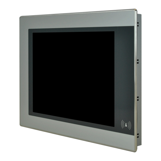
USB 2.0 The USB interfaces are protected by a shared maintenance-free "USB current-limiting switch" (total max. 1 A). 4.1.6 Features of AP1000 panels A wide selection of different display sizes and panels with touch screen and RFID read/write unit are available. -
Page 42: Individual Components
Technical data Information: The tag must be help ca. 0.5 cm from the front of the device for the RFID read/write unit to function properly (ISO 15693 and ISO 14443). Placing flush may cause a temporary loss of communication. Information: For additional information about the RFID read/write unit, see the technical description for the 5E9020.29. - Page 43 Technical data Order number 5AP1120.0702-I00 Operating conditions Pollution degree per EN 61131-2 Pollution degree 2 Suitable for hygienic applications Degree of protection per EN 60529 Front: IP69K Back: IP20 (only with installed link module or installed system unit) Degree of protection per UL 50 Front: Type 4X indoor use only Mechanical properties Front...
-
Page 44: 5Ap1125.1043-I00
Technical data 4.2.1.2 5AP1125.1043-I00 4.2.1.2.1 General information • 10.4" color TFT display, VGA • Single-touch (analog, resistive), with fully laminated panel overlay (shatter protection) • IP69K protection (front) • Front and housing made of stainless steel (hygienic design, no dirt-collecting edge) •... - Page 45 Technical data Order number 5AP1125.1043-I00 Mechanical properties Front Frame Stainless steel 1.4301 Panel overlay Material Polyester Light background color RAL 9006 Dark border color around display RAL 7024 Gasket Silicone rubber Dimensions Width 321 mm Height 261 mm Weight 4,100 g Table 7: 5AP1125.1043-I00 - Technical data At an ambient temperature of 25°C.
-
Page 46: 5Ap1125.1044-I00
Technical data 4.2.1.3 5AP1125.1044-I00 4.2.1.3.1 General information • 10.4" color TFT display, SVGA • Single-touch (analog, resistive), with fully laminated panel overlay (shatter protection) • IP69K protection (front) • Front and housing made of stainless steel (hygienic design, no dirt-collecting edge) •... - Page 47 Technical data Order number 5AP1125.1044-I00 Mechanical properties Front Frame Stainless steel 1.4301 Panel overlay Material Polyester Light background color RAL 9006 Dark border color around display RAL 7024 Gasket Silicone rubber Dimensions Width 321 mm Height 261 mm Weight 4,300 g Table 9: 5AP1125.1044-I00 - Technical data At an ambient temperature of 25°C.
-
Page 48: 5Ap1125.1505-I00
Technical data 4.2.1.4 5AP1125.1505-I00 4.2.1.4.1 General information • 15.5" color TFT display, XGA • Single-touch (analog, resistive), with fully laminated panel overlay (shatter protection) • IP69K protection (front) • Front and housing made of stainless steel (hygienic design, no dirt-collecting edge) •... - Page 49 Technical data Order number 5AP1125.1505-I00 Mechanical properties Front Frame Stainless steel 1.4301 Panel overlay Material Polyester Light background color RAL 9006 Dark border color around display RAL 7024 Gasket Silicone rubber Dimensions Width 433 mm Height 331 mm Weight 6,900 g Table 11: 5AP1125.1505-I00 - Technical data At an ambient temperature of 25°C.
-
Page 50: Link Modules
Technical data 4.2.2 Link modules 4.2.2.1 5DLSDL.1001-00 4.2.2.1.1 General information • Link module for Automation Panel 9x3/1000/5000 • 1x SDL/DVI Panel In interface • 2x USB 2.0 type A • 1x USB In (USB type B) • 1x RS232 interface •... - Page 51 Technical data Order number 5DLSDL.1001-00 Operating conditions Pollution degree per EN 61131-2 Pollution degree 2 Mechanical properties Dimensions Width 190 mm Height 110 mm Depth 23.6 mm Weight 538 g The brightness controls can be used to set the brightness of the backlight on the Automation Panel in DVI operation. Yes, but applies only if all components installed in the complete system have this certification and the complete system bears the corresponding mark.
-
Page 52: 5Dlsd3.1001-00
Technical data 4.2.2.2 5DLSD3.1001-00 4.2.2.2.1 General information • Link module for Automation Panel 9x3/1000/5000 • 1x SDL3 Panel In interface • 2x USB 2.0 type A 4.2.2.2.2 Order data Order number Short description Figure Link modules 5DLSD3.1001-00 Automation Panel link module - SDL3 receiver - For Automation Panel 923/933/1000 - For Automation Panel 5000 Required accessories Accessories... - Page 53 Technical data Order number 5DLSD3.1001-00 Electrical properties Nominal voltage 24 VDC ±25%, SELV Nominal current Max. 3 A Overvoltage category per EN 61131-2 Galvanic isolation Operating conditions Pollution degree per EN 61131-2 Pollution degree 2 Mechanical properties Dimensions Width 190 mm Height 110 mm Depth...
-
Page 54: 5Dlsd4.1001-00
Technical data 4.2.2.3 5DLSD4.1001-00 4.2.2.3.1 General information • Link module for Automation Panel 9x3/1000/5000 • 1x SDL4 Panel In interface • 2x USB 2.0 type A 4.2.2.3.2 Order data Order number Short description Figure Link modules 5DLSD4.1001-00 Automation Panel link module - SDL4 receiver - For Automation Panel 923/933/1000 - For Automation Panel 5000 Required accessories Accessories... - Page 55 Technical data Order number 5DLSD4.1001-00 Operating conditions Pollution degree per EN 61131-2 Pollution degree 2 Mechanical properties Dimensions Width 190 mm Height 110 mm Depth 23.6 mm Weight 525 g EN 60950 requirements must be observed; see section "+24 VDC power supply" of the data sheet. Automation Panel 1000 - Hygienic design user's manual V2.00...
-
Page 56: Installation And Wiring
Installation and wiring 5 Installation and wiring 5.1 Basic information A damaged device has unpredictable properties and states. The unintentional installation or startup of a damaged device must be prevented. The damaged device must be marked as such and made inaccessible, or it must be returned for repairs immediately. - Page 57 Installation and wiring • The device is only permitted to be operated in closed rooms and not permitted to be exposed to direct sunlight. • The climatic and ambient conditions must be taken into account – see "Environmental properties" on page General installation instructions •...
-
Page 58: Installation Cutout Requirements
Installation and wiring 5.2 Installation cutout requirements When installing the panel, it is important to ensure that the surface and wall thickness meet the following conditions: Properties of the installation cutout Value Permissible deviation from the evenness ≤0.5 mm Note: This condition must also be met with the device installed. Permitted surface roughness in the area of the seal ≤120 µm (R z 120) Min. - Page 59 Installation and wiring 3. Install the retaining clips on the device. To do this, insert all retaining clips into the recesses (marked with orange circles) on the device. The number of retaining clips can vary depending on the panel; for the exact number, see the individual panels.
-
Page 60: Switch The Link Module
Installation and wiring 5.4 Switch the link module 1. Disconnect the power supply cable to the Automation Panel (disconnect the power cable). Disconnect from all sources and poles! 2. Carry out electrostatic discharge at the ground connection. 3. Remove the Automation Panel from the control cabinet by following the installation steps in reverse order. 4. -
Page 61: Installing The Dc Power Cable
Installation and wiring 5.5.1 Installing the DC power cable Danger! The entire power supply to the B&R industrial PC or B&R Automation Panel must be interrupted. Before connecting the DC power cable, it must be checked whether it has been disconnected from the voltage source (e.g. -
Page 62: Connecting The Power Supply To A B&R Device
Installation and wiring 5.5.2 Connecting the power supply to a B&R device Danger! The entire power supply to the B&R device must be interrupted. Before connecting the power cable, it must be checked whether it has been disconnected from the voltage source (e.g. power supply unit). 1. -
Page 63: Grounding Concept - Functional Ground
Installation and wiring 5.5.3 Grounding concept - Functional ground Functional ground is a current path of low impedance between circuits and ground. It is used to improve immunity to interference, for example, and not as a protective measure. It serves only to divert interference, not to protect against contact with persons. -
Page 64: Connecting Cables
Installation and wiring 5.6 Connecting cables When connecting or installing cables, the bend radius specification must be observed. For this specification, see the technical data of the respective cable. The maximum tightening torque of the locating screws is 0.5 Nm. Bend radius Locating screws Automation Panel 1000 - Hygienic design user's manual V2.00... -
Page 65: Commissioning
Commissioning 6 Commissioning 6.1 Basic information Before the device is started up, it must be gradually adapted to room temperature! 6.2 Switching on the device for the first time 6.2.1 General information before switching on the device Checklist Before the device is started up for the first time, the following points must be checked: •... -
Page 66: Touch Screen Calibration
Commissioning 6.3 Touch screen calibration B&R touch screen devices are equipped with a B&R touch controller that supports hardware calibration. These devices come already pre-calibrated from the factory. This feature offers great advantages especially for replace- ment parts since recalibration is usually no longer required when replacing a device (identical model/type). B&R still recommends recalibration for best results and to optimally adapt the touch screen to the needs of the user. -
Page 67: Display Brightness Control
Commissioning On all other devices, the touch screen driver must be subsequently installed to operate the touch screen. The appropriate driver is available for download in the Downloads section of the B&R website (www.br-automation.com). 6.4 Display brightness control In SDL, SDL3 or SDL4 operation, the brightness of the display can be configured using the B&R Control Center on the connected B&R industrial PC, for example. -
Page 68: Software
Software 7 Software 7.1 Upgrade information Warning! The BIOS and firmware on B&R devices must always be kept up to date. New versions can be down- loaded from the B&R website (www.br-automation.com). 7.1.1 Automation Panel firmware upgrade With Firmware upgrade (Automation Panel, SDL3 Converter, SLD4 converter), it is possible to update the firmware of several controllers (SDLR, SDL3R, SDL4R, SDL3 Converter, SDL4 Converter) depending on the variant of the system. -
Page 69: Automation Runtime
Software 7.2 Automation Runtime 7.2.1 General information The Automation Runtime real-time operating system is an integral part of Automation Studio. This real-time oper- ating system makes up the software kernel that allows applications to run on a target system. • Guarantees the highest possible performance of the hardware being used •... -
Page 70: Adi Control Center
Software 7.3 ADI Control Center The settings of B&R devices can be read out and changed in Windows using the ADI Control Center in the Control Panel. The figure shown is a symbolic image; the representation may vary depending on the device. Information: The displayed temperature and voltage values (e.g. -
Page 71: Adi Development Kit
Software 7.4 ADI Development Kit This software allows ADI functions to be accessed from Windows applications created with Microsoft Visual Studio, for example: Figure 15: ADI Development Kit screenshots Features: • Header files and import libraries • Help files • Example projects •... -
Page 72: Adi .Net Sdk
Software 7.5 ADI .NET SDK This software allows ADI functions to be accessed from .NET applications created with Microsoft Visual Studio. Figure 16: ADI .NET SDK screenshots Features: • ADI .NET class library • Help files (in English) • Sample projects and code snippets •... -
Page 73: Hmi Service Center
Software 7.6 HMI Service Center 7.6.1 5SWUTI.0001-000 7.6.1.1 General information The HMI Service Center is software for testing B&R industrial PCs and Automation Panels. Testing covers different categories such as COM, network and SRAM. The test system consists of a USB flash drive with installed Windows PE operating system and the HMI Service Center. -
Page 74: Maintenance
Maintenance 8 Maintenance The following chapter describes the maintenance work that can be carried out by a qualified and trained end user. Information: Only components approved by B&R are permitted to be used for maintenance work. 8.1 Cleaning Danger! In order to prevent unintentional operation (by touching the touch screen or keys), the device is only permitted to be cleaned when the power is switched off. -
Page 75: User Tips For Increasing The Service Life Of The Display
Maintenance 8.2 User tips for increasing the service life of the display 8.2.1 Backlight The service life of the backlight is specified by its "half-brightness time". An operating time of 50,000 hours would mean that the display brightness would still be 50% after this time. 8.2.1.1 Measures to maintain backlight service life •... - Page 76 Maintenance To process a repair/complaint, a repair order or complaint must be created via the B&R Material Return Portal on the B&R website (www.br-automation.com). Automation Panel 1000 - Hygienic design user's manual V2.00...
-
Page 77: Accessories
Accessories 9 Accessories The following accessories have undergone functional testing by B&R in connection with the device used and can be operated with this device. Possible limitations regarding operation with individual components other than the complete system must be taken into account, however. All individual specifications of the components must be observed when operating the complete system. - Page 78 Accessories Order number 0TB103.9 0TB103.91 Terminal block Note Protected against vibration by the screw flange Protected against vibration by the screw flange Nominal values according to UL Nominal data per UL Number of pins 3 (female) Type of terminal block Screw clamp terminal block Cage clamp terminal block variant Cable type...
-
Page 79: Usb Flash Drives
Accessories 9.3 USB flash drives 9.3.1 5MMUSB.xxxx-01 9.3.1.1 General information USB flash drives are easily replaceable storage media. Due to the fast data transfer (USB 2.0), USB flash drives offer optimal values for use as portable storage media. Without additional drivers, the USB flash drive immediately reports itself as another drive from which data can be read or to which data can be written (hot plugging). -
Page 80: Temperature/Humidity Diagram
Accessories Order number 5MMUSB.2048-01 5MMUSB.4096-01 Support Operating systems Windows 10 IoT Enterprise LTSB 64-bit Windows Embedded 8.1 Industry Pro 32-bit Windows Embedded 8.1 Industry Pro 64-bit Windows 7 32-bit Windows 7 64-bit Windows Embedded Standard 7 32-bit Windows Embedded Standard 7 64-bit Windows XP Professional Windows XP Embedded Windows 2000... -
Page 81: 5Mmusb.032G-02
Accessories 9.3.2 5MMUSB.032G-02 9.3.2.1 General information USB flash drives are easily replaceable storage media. Due to the fast data transfer (USB 3.0), USB flash drives offer optimal values for use as portable storage media. Without additional drivers, the USB flash drive immediately reports itself as another drive from which data can be read or to which data can be written (hot plugging). -
Page 82: Temperature/Humidity Diagram
Accessories Order number 5MMUSB.032G-02 Vibration Operation 7 to 2000 Hz: 20 g Storage 7 to 2000 Hz: 20 g Transport 7 to 2000 Hz: 20 g Shock Operation 1500 g, 0.5 ms Storage 1500 g, 0.5 ms Transport 1500 g, 0.5 ms Elevation Operation Max. -
Page 83: Cables
Accessories 9.4 Cables For additional information about compatible cables, see the B&R website (HMI cable manual). Automation Panel 1000 - Hygienic design user's manual V2.00... -
Page 84: Replacement Gaskets
Accessories 9.5 Replacement gaskets 9.5.1 5ACCRAP1.0000-000, 5ACCRAP1.0001-000, 5ACCRAP1.0002-000 9.5.1.1 General information Replacement gaskets are available as optional accessories. 9.5.1.2 Order data Order number Short description Figure Accessories 5ACCRAP1.0000-000 Replacement gasket 5AP1120.0702-I00 1 pc. 5ACCRAP1.0001-000 Replacement gasket 5AP1125.104x-I00 1 pc. 5ACCRAP1.0002-000 Replacement gasket 5AP1125.1505-I00 1 pc. -
Page 85: International And National Certifications
International and national certifications 10 International and national certifications 10.1 Directives and declarations 10.1.1 CE marking All directives applicable to the respective product and their harmonized EN standards are met. 10.1.2 EMC Directive The products meet the requirements of EU directive "Electromagnetic compatibility 2014/30/EU" and are designed for industrial applications: EN 61131-2:2007 Programmable controllers - Part 2: Equipment requirements and tests... -
Page 86: Certifications
International and national certifications 10.2 Certifications Danger! A complete system can only receive certification if all individual components installed and connected in it have the corresponding certifications. If an individual component is used that does not have the corresponding certification, the complete system will also not be certified. B&R products and services comply with applicable standards. -
Page 87: Environmentally Friendly Disposal
Environmentally friendly disposal 11 Environmentally friendly disposal All programmable logic controllers, operating and monitoring devices and uninterruptible power supplies from B&R are designed to have as little impact on the environment as possible. 11.1 Separation of materials To ensure that devices can be recycled in an environmentally friendly manner, it is necessary to separate out the different materials. -
Page 88: Abbreviations
Appendix A Appendix A A.A Abbreviations Abbreviations used in the document are explained here. Abbreviation Stands for Description Normally closed Stands for a normally closed relay contact. Not connected Used in pinout descriptions if a terminal or pin is not connected on the module side. -
Page 89: Chemical Resistance
Appendix A A.3 Chemical resistance Panels are manufactured with the Autotex panel overlay: Stainless steel front (frame) Keypad overlay A.3.1 Autotex panel overlay (polyester) Unless otherwise specified, the panel overlay is resistant to the following chemicals per DIN 42115 Part 2 when exposed for up to 24 hours without visible changes: •...
Need help?
Do you have a question about the AP1000 and is the answer not in the manual?
Questions and answers