Table of Contents
Advertisement
1. INTRODUCTION
This manual provides information on the installation, configuration and use of the main instrument
functions.
The manual is not intended for general use, but for qualified technicians.
This term indicates a professional and skilled technician, authorised to act in accordance with the safety
standards relating to the dangers posed by electric current.
This person must also have basic first aid training and be in possession of suitable Personal Protective
Equipment.
WARNING!
It is strictly forbidden for anyone who does not fulfill the above-mentioned requirements
to install or use the instrument.
The instrument complies with the European Union directives in force, as well as with the technical standards
implementing these requirements, as certified by the CE mark on the device and on this Manual.
Using the meter for purposes other than intended ones, understood by the manual content, is strictly
forbidden. The information herein contained shall not be shared with third parties. Any duplication of this
manual, either partial or total, not authorised in writing by the Manufacturer and obtained by photocopying,
duplicating or using any other electronic means, violates the terms of copyright and is punishable by law.
Any brands quoted in the publication belong to the legitimate registered owners.
WARNING!
In case of 25A instrument version, pay attention as it is designed for direct connection
with 25A nominal current, without external CTs. CT ratio usually programmable in the
device is factory preset to 5 and FSA to 5A. Do not change these values.
NOTE. This manual describes the use of the main instrument functions.
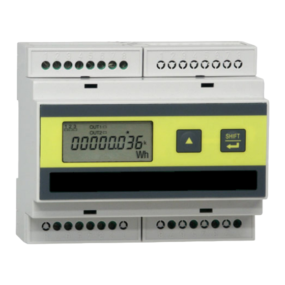
UPT210
UNIVERSAL POWER TRANSDUCER
USER MANUAL
Advertisement
Table of Contents

Summary of Contents for Algodue ELETTRONICA UPT210
- Page 1 UPT210 UNIVERSAL POWER TRANSDUCER USER MANUAL 1. INTRODUCTION This manual provides information on the installation, configuration and use of the main instrument functions. The manual is not intended for general use, but for qualified technicians. This term indicates a professional and skilled technician, authorised to act in accordance with the safety standards relating to the dangers posed by electric current.
-
Page 2: Graphic Symbols
LCD display provides the three-phase quantities. The working parameters can be easily set up by instrument keypad. UPT210 is a compact, cost effective meter operating both as a stand-alone device or as an integral part of a more extensive energy monitoring and management network. -
Page 3: Installation
5. INSTALLATION NOTE. The equipment complies with the 89/366/EEC, 73/23/EEC standards and following amendments. However, if not properly installed, it may generate a magnetic field and radio interference. This is why compliance with EMC standards on electromagnetic compatibility is essential. 5.1 ENVIRONMENTAL REqUIREMENTS The environment in which the instrument is installed must satisfy the following features: •... - Page 4 7. ELECTRICAL CONNECTIONS The instrument must be installed according to the following order: A B C + - WARNING! Before making any connection, check that the control panel main switch is OFF. Digital outputs. See section 7.2 19÷60V power supply (option on request). See section 7.4 Serial port (option on request).
-
Page 5: Digital Outputs
7.2 DIGITAL OUTPUTS The instrument is equipped with two digital outputs. The digital outputs can be used for pulse emission. WARNING! Before connecting or disconnecting the digital outputs, be sure that the instrument is not powered. The power supply line, the measurement inputs and any other voltage source must be A) PNP wiring (10-50V) disconnected. - Page 6 WIRING DIAGRAM: 3 phAses - 4 WIRes / 3 cuRReNt tRANsfoRMeRs (3.4.3) connection Pict. A: direct connection (3.4.3) Pict. B: direct connection (3.4.3) * with serial communication port WIRING DIAGRAM: 1 phAse (1ph) connection Pict. C: direct connection (1ph) Pict. D: direct connection (1ph) * with serial communication port WIRING DIAGRAM: 3 phAses - 3 WIRes / 3 cuRReNt tRANsfoRMeRs (3.3.3) connection (on request) Pict.
-
Page 7: Instrument Version
25A INSTRUMENT VERSION WARNING! Every wiring diagram must be provided with fuses (F1, F2, F3, FN) or another similar protection as indicated in the picture. The F1/F2/F3 value will depend on the load. The FN value is 100mA and it is required only when the instrument is provided with serial port. WIRING DIAGRAM: 3 phAses - 4 WIRes / 3 cuRReNt tRANsfoRMeRs (3.4.3) connection WIRING DIAGRAM: 1 phAse (1ph) connection WIRING DIAGRAM: 3 phAses - 3 WIRes / 3 cuRReNt tRANsfoRMeRs (3.3.3) connection (on request) -
Page 8: Power Supply
7.3.1 Voltage specifications The standard meter is designed for measurements on 230/400 V 3-phase systems with neutral wire. Other voltages and configurations are available on request. Input impedance ›1,3 MOhm Burden max 0,15 VA per phase 7.3.2 Current specifications The phase and polarity of the current input is an essential parameter for proper parameters indication. The standard current specifications are listed below: Rated current (Ib) 1 / 5 A... -
Page 9: Control Panel Description
8. USE AND CONFIGURATION NOTE. The pages described in this manual refer to the instrument for 3PHASES, 4WIRES, 3CTs connection. Some pages may differ or disappear if the wiring mode is different. 8.1 DISPLAYED PAGES All displayed pages are structured in four loops: •... -
Page 10: Preliminary Inspections
8.4 PRELIMINARY INSPECTIONS At the end of the installation check that the setting corresponds to the wiring: enter the instrument setup according to the content of next chapter and set the wiring diagram, the CT ratio and the PT ratio. 8.5 SETUP 8.5.1 Access to SETUP It allows to configure the device to fit the application. - Page 11 Integration time [DMD] NOTE: The Integration time page availability depends on the instrument model. This page allows to set the integration time for demand values calculation. The demand values are calculated only on positive values and in a programmed period (e.g.
- Page 12 In case of bidirectional values, option on request, exported energy variables can be selected for digital output pulse weight setup. The multiplying factor ([ ] none, [k] kilo, [M] mega) and the decimal point depend on the selected CT and PT value.
-
Page 13: Diagnostic Functions
9. DIAGNOSTIC FUNCTIONS The diagnostic functions allow to check if there is any error in the instrument connections or one of the measured voltage and/or current is out of range; the instrument can display some symbols with a specific meaning. Hereafter the description of the available diagnosis: Function Condition Display... -
Page 14: Maintenance
10. MAINTENANCE The instrument is maintenance-free. Clean the display and keyboard, if required, using a clean cloth and non-aggressive cleaning liquid. Do not use solvents or detergents which may damage plastic parts. 11. TECHNICAL FEATURES AUXILIARY POWER SUPPLY Rated voltage powered from measuring inputs external power supply 19÷60V (on request) -
Page 15: Environmental Conditions
ENVIRONMENTAL CONDITIONS Operating temperature between -15°C and +60°C (+5°F and +140°F) Storage temperature between -25°C and +75°C (-13°F and +167°F) Relative humidity 80% max without condensation MECHANICAL CHARACTERISTICS Material plastic enclosure - noryl UL94-V0 Protection degree IP51 (front panel); IP20 (terminals) Terminals conductors 2.5mm Size / Weight... - Page 16 DISPLAYED PAGES ENERGY COUNTERS PAGES [1° loop] Imported active energy [Wh] Exported lagging reactive energy [varh ind] (optional) Exported active energy[Wh] Imported lagging reactive energy (optional) [varh ind] Imported apparent energy [VAh] Exported leading reactive energy [varh cap] (optional) Exported apparent energy [VAh] Imported leading reactive energy (optional) [varh cap]...
- Page 17 INSTANTANEOUS VALUES PAGES [2° loop] L-N phase 1 voltage [V] L-N phase 2 voltage [V] L-N phase 3 voltage [V] L-L line 12 voltage [V] Frequency [Hz] L-L line 23 voltage [V] L-L line 31 voltage [V] System voltage [V] System powerfactor Phase 1 powerfactor Phase 1 current [A]...
- Page 18 DMD & PEAK VALUES PAGES [3° loop] (optional) Peak of L-N phase 1 voltage [V] Peak of L-N phase 2 voltage [V] Peak of system apparent power DMD [VA] Peak of L-N phase 3 voltage [V] Peak of L-L line 12 voltage [V] Peak of L-L line 23 voltage [V] Peak of system active power DMD [W] Peak of L-L line 31 voltage [V]...
Need help?
Do you have a question about the UPT210 and is the answer not in the manual?
Questions and answers