
Related Manuals for FRIENDCOM PULSE915-LRW

Summary of Contents for FRIENDCOM PULSE915-LRW
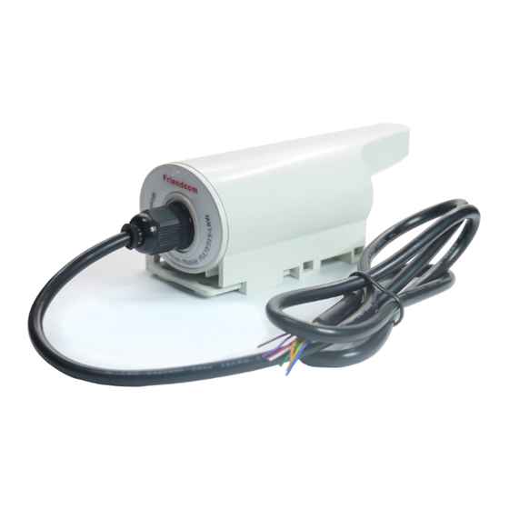
- Page 1 PULSE915-LRW Terminal User Manual LoRaWAN Terminal Series Version 2.1 Date: 2020-09-11 www.friendcom.com...
- Page 2 To comply with RF exposure requirements, a minimum separation distance of 20cm must be maintained between the user’s body and the device, including the antenna. Friendcom has always been committed to technological innovation. Our aim is to provide customers with timely and comprehensive service. For any assistance, please contact our Shenzhen headquarters: FRIENDCOM TECHNOLOGY CO., LTD.
-
Page 3: About This Document
However, Friendcom assumes no liability resulting from any inaccuracies or omissions in this document, or from use of the information obtained herein. Friendcom reserves the right to make changes to any products described herein and reserves the right to revise this document and to make changes from time to time in content hereof with no obligation to notify any person of revisions or changes. - Page 4 PULSE915-LRW_User_Manual Related Documents Friendcom_PULSE915-LRW_Terminal_Datasheet Friendcom_PULSE915-LRW_Configuration_User_Manual Conventions Symbol Indication This warning symbol means danger. You are in a situation that could cause fatal device damage or even bodily damage. Means reader be careful. In this situation, you might perform an action that could result in module or product damages.
- Page 5 PULSE915-LRW_User_Manual History Issue Date Change 2018-05 Initial draft Update Interface definition Added pulse wiring method of Hall sensor type 2019-06 Update the format of proactive data reporting Added data short frame format Update magnet active time and corresponding functions ...
-
Page 6: Table Of Contents
PULSE915-LRW_User_Manual Content About This Document............................2 Table Index................................6 Figure Index................................7 1 Introduction............................... 8 2 Product Concept..............................8 2.1 General Description..........................8 2.2 Key Features............................8 2.3 Specifications............................9 2.4 Communication Interface........................9 2.5 Safety Recommendations........................10 3 Wiring Definition..............................10 3.1 Wiring definition........................... 10 3.2 Pulse Acquisition...........................11 3.2.1 Active Pulse..........................12 3.2.2 Passive Pulse.......................... - Page 7 PULSE915-LRW_User_Manual Table Index Table 2- 1 Specifications of PULSE915-LRW....................9 Table 3- 1 Wiring definition of PULSE915-LRW..................11 Table 3- 2 Active pulse wiring........................12 Table 3- 3 Passive Pulse wiring....................... 12 Table 4- 1 Format of commands......................14 Table 5- 1 Device to USB wiring......................18...
- Page 8 PULSE915-LRW_User_Manual Figure Index Figure 3- 1 PCB wiring diagram......................11 Figure 5- 1 Magnet activation position....................19 Figure 6- 1 Dimensions of PULSE915-LRW..................... 21 Figure 6- 2 Installation of PULSE915-LRW....................22 Page 7 / 23...
-
Page 9: Introduction
LoRaWAN technology to implement active data reporting. PULSE915-LRW supports two kinds of pulse signal output sensors of Hall and reed switch. That enables it to operate with any pulse emitting device (water, gas, electricity, etc.). -
Page 10: Specifications
“*” Means for features and certifications in planning Communication Interface PULSE915-LRW has a UART communication port and a set of pulse signal input ports. UART interface can be used for parameters configuration and firmware upgrades, and the Page 9 / 23... -
Page 11: Safety Recommendations
Do not use this product at any places with a risk of fire or potentially explosive atmospheres such as gasoline stations, oil refineries, etc. Wiring Definition Wiring definition PULSE915-LRW uses wiring terminal for connection. The name of each terminal is marked on the PCB. Page 10 / 23... -
Page 12: Pulse Acquisition
Wire break detection Pulse Acquisition PULSE915-LRW collects pulses and counts them, and the current accumulated index is sent to the gateway through the LoRaWAN module according to the preset reporting period, and finally uploaded to LoRaWAN server. The connection between active pulse (Hall) and passive pulse (reed switch) is as follows. -
Page 13: Active Pulse
Data Format And Setting Command Data Format Of Reporting PULSE915-LRW actively reports data according to the set period. The format of reported data frame can be set to two types: short format and long format. The information reported in the two formats is different, as follows:... - Page 14 PULSE915-LRW_User_Manual Short data frame format: Name Byte Note Frame header Fixed 0x56 Bit 4- Bit 7: Frame number Bit 3: NC Frame number Bit 2: Magnetic interference flag, 0 means normal, 1 means abnormal. and status Bit 1: Broken line sign, 0 means normal, 1 means abnormal Bit 0: Low voltage alarm flag, 0 means normal, 1 means abnormal The device address, the factory default is the last 4 bytes of LoRaWAN Address field...
-
Page 15: Setting Command
FD is the checksum, cumulative sum from the frame header to the previous byte End character, fixed to 0x16 Setting Command Parameters of PULSE915-LRW can be set and read by AT command, the format of commands is shown in the following table. Table 4- 1 Format of commands Command... - Page 16 PULSE915-LRW_User_Manual Query the current InitValue = xxx.xx AT+I electronic index, the unit Error is m³ Set the initial index, such as the current value of meter. Max. value is 5 integers and 3 decimal, the unit is m³. AT+I=xxxxx.xxx Set InitValue = xxxxx.xxx Error For example, to set the initial index is 55.123,...
- Page 17 PULSE915-LRW_User_Manual hexadecimal digits. Example: AT+DA =ABCDEF01 Read pull-up resistor configuration of external Vcc = **(ON), Pull Up = AT+VP Vcc and two pulse **(OFF) sampling ports Set pull-up resistor of external Vcc and two pulse sampling ports. AT+VP=”vcc Set Vcc = ON, Pull Up = ON is open state”,”Pull up state”...
- Page 18 PULSE915-LRW_User_Manual Set the frequency band. For example, set the AT+DR=band band to AU915. The +DR: XXXXXX command is: AT+DR=AU915. Set channel. The transmit channel of the module must be consistent with the receive channel of the AT+CH=NUM, chm-chn +CH: NUM, 0-7 gateway.
-
Page 19: Parameters Configuration
Parameters Configuration Parameters Configuration Before using the PULSE915-LRW terminal, we need to configure some parameters, such as initial index, pulse constant, RTC real-time clock, pulse type (single or double pulse), sensor type (hall or reed switch) and other LoRaWAN information. The configuration mode supports wired wireless. -
Page 20: Entering Configuration Mode
PULSE915-LRW_User_Manual 5.1.3 Entering Configuration Mode PULSE915-LRW terminal can be activated by magnet to enter configuration mode. Both the wired configuration mode and wireless configuration mode need to be activated before parameters configured. The reed switch inside the product is triggered by the magnet to put the product into the configuration mode, and then the configuration command must be sent within 30 seconds. -
Page 21: Dimensions And Installation Instructions
The parameters can be set through AT command, for detailed command information, please refer to section 4.2. Dimensions and Installation Instructions Dimensions The dimensions of PULSE915-LRW is show blew (not contains the cable, unit mm). Page 20 / 23... - Page 22 PULSE915-LRW_User_Manual Figure 6- 1 Dimensions of PULSE915-LRW Page 21 / 23...
-
Page 23: Installation
PULSE915-LRW_User_Manual Installation Figure 6- 2 Installation of PULSE915-LRW Installation method: 1) Ties installed in water pipes 2) Use screw to fixed it through side fixing holes 3) Mounted on DIN35 rails 4) Use screw to fixed it through front fixing holes Transportantion and Storage Storage: -5C to 55C, non-corrosive gases.
Need help?
Do you have a question about the PULSE915-LRW and is the answer not in the manual?
Questions and answers