
Summary of Contents for VXI Technology VM3618
- Page 1 sales@artisantg.com artisantg.com (217) 352-9330 | Visit our website - Click HERE...
- Page 2 VM3618 SOLATED IGITAL NALOG ONVERTER ’ ANUAL 82-0028-000 Release December 1, 2003 VXI Technology, Inc. 2031 Main Street Irvine, CA 92614-6509 (949) 955-1894...
-
Page 4: Table Of Contents
Scan Table................................34 Scan Table Location ............................35 Source Current Level ............................36 Source Data................................37 Source Setup ..............................38 Source Voltage Level............................39 Trigger Sequence Immediate ..........................40 Trigger Sequence Slope .............................41 Trigger Sequence Source ...........................42 Application Examples.............................43 Register Access Examples ............................44 VXIplug&play Examples ............................47 VM3618 Introduction... - Page 5 VXI Technology, Inc. 4 ...................................55 ECTION Command Dictionary..............................55 Introduction................................55 Alphabetical Command Listing .........................55 The <channel_list> Parameter ...........................56 Command Dictionary............................60 IEEE 488.2 Common Commands...........................61 *CLS ..................................61 *ESE ..................................62 *ESR? ................................63 *IDN?.................................64 *OPC..................................65 *RST ..................................66 *SRE ..................................67 *STB? ................................68 *TRG..................................69 *TST?.................................70 *WAI..................................71 Instrument Specific SCPI Commands ........................72...
- Page 6 5 .................................107 ECTION Theory of Operation .............................107 Introduction..............................107 Interface and Control FPGA ..........................108 Reference and Calibration..........................110 ..................................111 NDEX VM3618 Introduction...
-
Page 7: Certification
VXI Technology, Inc. shall not be liable for injury to property other than the goods themselves. Other than the limited warranty stated above, VXI Technology, Inc. makes no other warranties, express or implied, with respect to the quality of product beyond the description of the goods on the face of the contract. -
Page 8: Declaration Of Conformity
RODUCT ONFIGURATIONS VXI Technology, Inc. declares that the aforementioned product conforms to the requirements of the Low Voltage Directive 73/23/EEC and the EMC Directive 89/366/EEC (inclusive 93/68/EEC) and carries the “CE” mark accordingly. The product has been designed and manufactured... - Page 9 VXI Technology, Inc. VM3618 Preface...
-
Page 10: General Safety Instructions
To avoid electrical overload, electric shock, or fire hazard, Use Proper Power Source do not use a power source that applies other than the specified voltage. To avoid fire hazard, only use the type and rating fuse Use Proper Fuse specified for this product. VM3618 Introduction... - Page 11 VXI Technology, Inc. ARNINGS To avoid electric shock or fire hazard, do not operate this Avoid Electric Shock product with the covers removed. Do not connect or disconnect any cable, probes, test leads, etc. while they are connected to a voltage source.
-
Page 12: Support Resources
UPPORT ESOURCES Support resources for this product are available on the Internet and at VXI Technology customer support centers. VXI Technology World Headquarters VXI Technology, Inc. 2031 Main Street Irvine, CA 92614-6509 Phone: (949) 955-1894 Fax: (949) 955-3041 VXI Technology Cleveland Instrument Division VXI Technology, Inc. - Page 13 VXI Technology, Inc. VM3618 Preface...
-
Page 14: Section 1
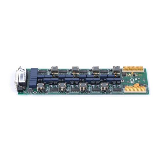
VMIP family to form a customized and highly integrated instrument (see Figure 1-1). This allows the user to reduce system size and cost by combining the VM3618 with two other instrument functions in a single-wide C-size VXIbus module. Figure 1-2 shows the 24- channel version of the VM3618. -
Page 15: Description
The VM3618 may be programmed to output a trigger on the VXI TTL trigger bus when the DACs are updated. The user may specify any one of the eight available trigger lines, or may disable the function if not needed. - Page 16 +5.0 V @ 2.70 A, -5.2 V @ 0.30 A, +24.0 V @ 2.10 A VM3618-3 ’ ANUFACTURER 3915 ODULE ODEL The manufacturer does not recommend combining VM3618 modules with VM2XXX series modules within Note: the same VMIP base unit. VM3618 Introduction...
- Page 17 VXI Technology, Inc. VM3618 Introduction...
-
Page 18: Section 2
All components should be immediately inspected for damage upon receipt of the unit. Once the VM3618 is assessed to be in good condition, it may be installed into an appropriate C-size or D-size VXIbus chassis in any slot other than slot zero. The chassis should be checked to ensure that it is capable of providing adequate power and cooling for the VM3618. -
Page 19: Setting The Chassis Backplane Jumpers
VMIP module. If dynamic address configuration is desired, the address switch should be set for a value of 255. Upon power-up, the slot 0 resource manager will assign logical addresses to each instrument in the VMIP module. VM3618 Preparation for Use... -
Page 20: Front Panel Interface Wiring
The connector for the VM3618 DAC board is a 44-pin female high-density D-Sub type. Connections listed are for the model VM3618 8-channel DAC board. A solder pot type mating connector is provided with each unit. Contact the factory for more connector information. The... -
Page 21: Mating Connectors
VXI Technology, Inc. Four voltage range settings are available on the VM3618: two bipolar (±10 V, ±16 V) and two unipolar (0 – 20, 0 – 32). The output pin is referenced to different reference pins depending on the range selected. The 20 mA current range operates per the bipolar configuration. -
Page 22: Section 3
ROGRAMMING NTRODUCTION The VM3618 is a VXIbus message-based device whose command set is compliant with the Standard Command for Programmable Instruments (SCPI) programming language. All module commands are sent over the VXIbus backplane to the module. Commands may be in upper, lower or mixed case. -
Page 23: Notation
VXI Technology, Inc. The following command is not correct because it uses part of the long form of SOURce, but not all the characters of the long form: sourc:volt:lev <value>,<channel_list> incorrect syntax - extra "c" All of the SCPI commands also have a query form unless otherwise noted. Query forms contain a question mark (?). -
Page 24: Scpi Command Examples
SCPI C OMMAND XAMPLES ALIBRATION OUNT The Calibration Count query returns the number of times the VM3618 module has been calibrated. CALibration:COUNt? There are no parameters for this command EXAMPLES CAL:COUN? Returns the number of times the VM3618 has been calibrated. -
Page 25: Calibration Gain
VXI Technology, Inc. ALIBRATION The Calibration Gain command is used to set the calibration constant for the gain of the selected channel; its effect is immediate. CALibration<channel>:GAIN <value> Where <channel> is the channel to be calibrated. Where <value> is the selected channel’s gain to be programmed. -
Page 26: Calibration Secure Code
EXAMPLES CAL:SEC:CODE #15OLIVE Programs the calibration security code as OLIVE. CAL:SEC:STAT OFF,#15OLIVE Disable the calibration security. CAL:SEC:CODE? Returns the current calibration security #15OLIVE code. The query can be performed only when the calibration security has been currently disabled. VM3618 Programming... -
Page 27: Calibration Secure State
VXI Technology, Inc. ALIBRATION ECURE TATE The Calibration Secure State command is used to enable or disable the calibration security state. CALibration:SECure:STATe <mode>[,<code>] Where <mode> specifies whether the security is to be enabled or disabled. Where <code> is the calibration security code. -
Page 28: Calibration Store
CAL:SEC:STAT OFF,#15OLIVE Disabling the calibration security. CAL2:GAIN 0.785500 Programming Channel 2’s gain constant. CAL1:ZERO 220 Programming Channel 1’s offset constant. CAL:STOR Storing the new calibration constants into the non-volatile memory. CAL:SEC:STAT ON Enabling the calibration security. VM3618 Programming... -
Page 29: Calibration Zero
VXI Technology, Inc. ALIBRATION The Calibration Zero command is used to set the calibration constant for the selected channel’s offset and its effect is immediate. CALibration<channel>:ZERO <value> Where <channel> specifies the channel whose calibration constant is to be programmed. Where <value> is the offset constant that is to be programmed for the specified channel. -
Page 30: Range
Channel 1 as ±20 mA. RANG? 1 Returns the current operating range for 20MA Channel 1. RANG 32V,(@2) Configuring operating range Channel 2 as 0 to 32 volts. RANG? 2 Returns the current operating range for Channel 2. VM3618 Programming... -
Page 31: Route Close
VXI Technology, Inc. OUTE LOSE The Route Close command is used to connect one or more channel outputs to their front panel connectors. ROUTe:CLOSe <channel_list> Where <channel_list> specifies channels whose outputs connected to their respective front panel connectors. For more details on the syntax of the channel list, see Section 4. -
Page 32: Route Open
ROUT:CLOS (@1:4) Connects the outputs of Channels 1 through 4 to their front panel connectors. ROUT:OPEN? 1 Returns whether the output of Channel 1 is disconnected from its front panel connector or not. VM3618 Programming... -
Page 33: Scan
VXI Technology, Inc. The Scan command enables or disables the operation of the scan list for the specified channels. SCAN <mode>,<channel_list> Where <mode> specifies the scan list operation mode to be configured for the specified channels. Where <channel_list> specifies the which... -
Page 34: Scan Limit
30. The interrupt routine loading the DAC 1 will load values from index 1 to 30 from the scan list after which it will loop back to zero and continue. SCAN:LIM? 1 Returns the scan limit corresponding to Channel 1. VM3618 Programming... -
Page 35: Scan Table
VXI Technology, Inc. ABLE The Scan Table command sets up the scan list for the specified channel. It allows entries of a list of voltage/current values to be placed in the specified channel’ scan list. SCAN:TABLe <channel>,<value_list> Where <channel> specifies the channel whose scan list is to be configured. -
Page 36: Scan Table Location
Channel 1 at index 6 as 4. SCAN:TABL1:LOC? 6 Returns the value from the scan list of 4.000244 Channel 1 at index 6. SCAN:TABL1:LOC? 3 Returns the value from the scan list of 2.999878 Channel 1 at index 3. VM3618 Programming... -
Page 37: Source Current Level
VXI Technology, Inc. OURCE URRENT EVEL The Source Current Level command sets the output current level of the specified channels. This command can be used for only those channels that are operating on the current range. If this command is used on channels operating on the voltage range, an error is generated. -
Page 38: Source Data
Channel 2 as ±16 V. SOUR:DATA -32768,(@2) Configures the voltage level for Channel 2 as –32768, which corresponds to -16 V on the ±16 V range. SOUR:DATA? 2 Returns the voltage level for Channel 2. -32768 VM3618 Programming... -
Page 39: Source Setup
VXI Technology, Inc. OURCE ETUP The Source Setup command loads each specified DAC with the value from the specified location in its respective scan list. SOURce:SETup <index>,<channel_list> Where <index> is a value in the range 1 to 512, which specifies the location in the specified channel’s scan list from where... -
Page 40: Source Voltage Level
Configures operating range Channels 1 and 2 to 0 to 32 V. SOUR:VOLT:LEV 10.1,(@1) Configures the output voltage level for Channel 1 to 10.1 V. SOUR:VOLT:LEV? 2 Returns the output voltage level for Channel 2 as 20 V. VM3618 Programming... -
Page 41: Trigger Sequence Immediate
VXI Technology, Inc. RIGGER EQUENCE MMEDIATE The Trigger Sequence Immediate command causes a trigger event to occur. TRIGger[:SEQuence]:IMMediate There parameters this command. EXAMPLES TRIG Causes a trigger event to occur. TRIG:SEQ Causes a trigger event to occur. TRIG:IMM Causes a trigger event to occur. -
Page 42: Trigger Sequence Slope
Configures the positive edge as the active edge of the triggering signal. TRIG:SLOP NEG Configures the negative edge as the active edge of the triggering signal. TRIG:SLOP? Returns the negative edge as the active edge of the triggering signal. VM3618 Programming... -
Page 43: Trigger Sequence Source
The Trigger Sequence Source configures the trigger event that will update the DACs on the VM3618 module. It must be noted that when using the SCAN mode of operation, a trigger source of either EXTernal or TTLT<n> must be selected TRIGger[:SEQuence]:SOURce <source>... -
Page 44: Application Examples
±20 mA range. ROUT:CLOS (@1,2) Connecting the outputs of Channels 1 and 2 to their front panel connectors. SOUR:VOLT:LEV 10.1,(@1) Setting Channel 1's voltage level to 10.1 V. SOUR:CURR:LEV 2.1,(@2) Setting Channel 2’s current level to 2.1 mA. VM3618 Programming... -
Page 45: Register Access Examples
VXI Technology, Inc. EGISTER CCESS XAMPLES This instrument can be programmed through the registers as well as through word serial commands. The programming registers are in the A16 address space. All registers are write-only registers in the real register mode and read/write in the pseudo register mode. Register offsets from the base address are shown in the following table. - Page 46 (See the Table 3-1for the register layout.) The Model VM3618 D/A Module supports access to the eight channels via the Device Dependent Registers of the VXIbus interface. The specific registers are located in A16 Memory at offsets 0x20=Port1, 0x22=Port2, 0x24=Port3, 0x26=Port4, 0x28=Port5, 0x2A=Port6, 0x2C=Port 7 and 0x2E=Port8.
- Page 47 VXI Technology, Inc. 3-1: A16 M ABLE EMORY Offset Description Channel 8 Channel 7 Channel 6 Channel 5 Channel 4 Channel 3 Channel 2 Channel 1 [ A32 Pointer Low ] [ A32 Pointer High ] [ A24 Pointer Low ]...
-
Page 48: Vxiplug&Play Examples
(1) to vtvm3618_PASSWORD_LEN_MAX (12). ViBooleanstoreDontstore, - This parameter specifies whether the calibration constants are to be stored in the Non-Volatile memory or not. Valid Range: Interpretation: ------------ --------------- vtvm3618_STORE Store Calibration Data vtvm3618_DONT_STORE Don't Store Calibration Data VM3618 Programming... - Page 49 VXI Technology, Inc. ViPInt32count, - This parameter returns the calibration count i.e., the number of times the module has been calibrated. Return Values: Returns VI_SUCCESS if successful. else returns error value. Description This function is an application function, which shows how the user can use core driver functions to calibrate the channels.
- Page 50 TTLT trigger sources. i.e., when the trigger source is one of the following vtvm3618_TRIG_SRC_EXT vtvm3618_TRIG_SRC_TTLTRG0 vtvm3618_TRIG_SRC_TTLTRG1 vtvm3618_TRIG_SRC_TTLTRG2 vtvm3618_TRIG_SRC_TTLTRG3 vtvm3618_TRIG_SRC_TTLTRG4 vtvm3618_TRIG_SRC_TTLTRG5 vtvm3618_TRIG_SRC_TTLTRG6 vtvm3618_TRIG_SRC_TTLTRG7 Valid Values: Interpretation: ------------ -------------- vtvm3618_SLOPE_POSITIVE Positive edge vtvm3618_SLOPE_NEGATIVE Negative edge ViReal32 outputLevel, - This parameter sets the output level for the specified channel(s). VM3618 Programming...
- Page 51 VXI Technology, Inc. Valid Range: ----------- For the 10 Volt Range: vtvm3618_VOLT_LEVEL_10V_MIN vtvm3618_VOLT_LEVEL_10V_MAX For the 16 Volt Range: vtvm3618_VOLT_LEVEL_16V_MIN vtvm3618_VOLT_LEVEL_16V_MAX For the 20 Volt Range: vtvm3618_VOLT_LEVEL_20V_MIN vtvm3618_VOLT_LEVEL_20V_MAX For the 20mA Range: vtvm3618_VOLT_LEVEL_20mA_MIN vtvm3618_VOLT_LEVEL_20mA_MAX For the 32 Volt Range: vtvm3618_VOLT_LEVEL_32V_MIN vtvm3618_VOLT_LEVEL_32V_MAX...
- Page 52 Scan Mode Loop. ViInt16 count, - This parameter specifies the position in the scan list array where the interrupt routine loading the DACs should either stop or loop back to zero. In other words, it specifies the scan limit. VM3618 Programming...
- Page 53 VXI Technology, Inc. Valid Range: ----------- vtvm3618_COUNT_MIN (1) to vtvm3618_COUNT_MAX (512). ViReal32 outputLevelList[], - This parameter specifies the output level values to be set in the scan list array of the specified channel. Each element of the array should be of the range specified below:...
- Page 54 * Configuring the Scan Mode of the specified channel status = vtvm3618_setupScanMode(instrHndl, mode, channelList, 1); if (status < VI_SUCCESS) return vtvm3618_ERROR_SETTING_SCAN_MODE; * Configuring the Scan List for the specified channel status = vtvm3618_setupScanList(instrHndl, channel, outputLevelList, numElems); if (status < VI_SUCCESS) return vtvm3618_ERROR_SETTING_SCAN_LIST; VM3618 Programming...
- Page 55 VXI Technology, Inc. * Configuring the Scan Limit Index in the scan array where the * interrupt routine loading the DAC will either stop or loop * back to zero depending on the scan mode status = vtvm3618_setupScanLimit(instrHndl, channel, count);...
-
Page 56: Section 4
OMMAND ISTING The following tables provide an alphabetical listing of each command supported by the VM3618 along with a brief description. If an X is found in the column titled *RST, then the value or setting controlled by this command is possibly changed by the execution of the *RST command. -
Page 57: The
Finally, a trailing right parenthesis ends the channel list. EXAMPLES: (@1) Channel 1 (@1,4) Channels 1 and 4 (@ 1,2,3,4) Channels 1, 2, 3 and 4 (@ 1:8) Channels 1, 2, 3, 4, 5, 6, 7 and 8 VM3618 Command Dictionary...Parameter - Page 58 Reset the module to a known state *SRE Set the Service Request Enable Register *STB? Query the Status Byte Register *TRG Causes a trigger event to occur *TST? Starts and reports a self-test procedure *WAI Halts execution and queries VM3618 Command Dictionary...
- Page 59 ABLE NSTRUMENT PECIFIC OMMANDS Command Description *RST Reset Value CALibration:COUNt? Query the number of times the VM3618 has been calibrated. CALibration:GAIN Set the calibration constant for the gain of the Values from selected channel. non-volatile memory CALibration:SECure:CODE Set the code required to disable calibration security.
- Page 60 Query the Questionable Status Condition Register STATus:QUEStionable:ENABle Sets the Questionable Status Enable Register STATus:QUEStionable[:EVENt]? Query the Questionable Status Event Register SYSTem:ERRor? Query the Error Queue Clears queue SYSTem:VERSion? Query which version of the SCPI standard the module complies with VM3618 Command Dictionary...
-
Page 61: Command Dictionary
Describes in detail what the command does and refers to additional sources. Description Present the proper use of each command and its query (when available). Examples Lists commands that affect the use of this command or commands that are affected Related Commands by this command. VM3618 Command Dictionary... -
Page 62: Ieee 488.2 Common Commands
None - Command Only Query Syntax Query Parameters Query Response This command clears all event registers, clears the OPC flag and clears all queues Description (except the output queue). Examples Command / Query Response (Description) *CLS None Related Commands VM3618 Command Dictionary... -
Page 63: Ese
Bit 0 - Operation Complete Bit 1 - Request Control (not used in the VM3618) Bit 2 - Query Error Bit 3 - Device Dependent Error (not used in the VM3618) Bit 4 - Execution Error Bit 5 - Command Error... -
Page 64: Esr
Bit 6 - User Request (not used in the VM3618, always 0) Bit 7 - Power On The Operation Complete bit is set by the VM3618 when it receives an *OPC command. The Query Error bit is set when data is over-written in the output queue. This could occur if one query is followed by another without reading the data from the first query. -
Page 65: Idn
Query Parameters ASCII character string Query Response The Identification query returns the identification string of the VM3618 module. The Description response is divided into four fields separated by commas. The first field is the manufacturer’s name, the second field is the model number, the third field is an optional serial number and the fourth field is the firmware revision number. -
Page 66: Opc
(ROUTe:CLOSe or ROUTe:OPEN), and changing ranges require relay operations. When a relay changes, the operation is not complete until the relay has had time to settle. Examples Command / Query Response (Description) *OPC *OPC? *WAI Related Commands VM3618 Command Dictionary... -
Page 67: Rst
The Reset command resets the module’s hardware and software to a known state. See Description the command tables at the beginning of this section for the default parameter values set by this command. Examples Command / Query Response (Description) *RST None Related Commands VM3618 Command Dictionary... -
Page 68: Sre
See the *STB? Command for the layout of bits. Note: Bit 6 is always internally cleared to zero as required by IEEE 488.2 section 11.3.2.3. Examples Command / Query Response (Description) *SRE 4 *SRE? None Related Commands VM3618 Command Dictionary... -
Page 69: Stb
Bit 3 - Questionable Status Summary (not used) Bit 4 - Message Available Bit 5 - Event Status Bit (ESB) Bit 6 - Master Summary Status Bit 7 - Operation Status Summary Examples Command / Query Response (Description) *STB? None Related Commands VM3618 Command Dictionary... -
Page 70: Trg
Command Syntax None Command Parameters *RST Value None - Command Only Query Syntax Query Parameters Query Response The Trigger command causes a trigger event to occur. Description Examples Command / Query Response (Description) *TRG TRIGger:SEQuence:IMMediate Related Commands VM3618 Command Dictionary... -
Page 71: Tst
None Query Parameters Numeric ASCII value from 0 to 255 Query Response The Self-Test query causes the VM3618 to run its self-test procedures and report on the Description results. The following tests are performed: 1. Non-volatile memory test 2. Timer test 3. -
Page 72: Wai
(ROUTe:CLOSe or ROUTe:OPEN), and changing ranges require relay operations. When a relay changes, the operation is not complete until the relay has had time to settle. Examples Command / Query Response (Description) *WAI *OPC Related Commands VM3618 Command Dictionary... -
Page 73: Instrument Specific Scpi Commands
VXI Technology, Inc. SCPI C NSTRUMENT PECIFIC OMMANDS CALibration:COUNt? Query the number of times the VM3618 has been calibrated Purpose Instrument specific SCPI Type None - Query Only Command Syntax Command Parameters *RST Value CALibration:COUNt? Query Syntax None Query Parameters... -
Page 74: Calibration:gain
Calibration commands should only be executed by qualified personnel. Changing these values incorrectly can cause the instrument to perform improperly Examples Command / Query Response (Description) CAL2:GAIN -120 CAL2:GAIN? -120 CALibration<channel>:ZERO <value> Related Commands CALibration:DATA <block_data> VM3618 Command Dictionary... -
Page 75: Calibration:secure:code
Description to the calibration commands. Calibration security must be disabled in order to change the code string. Before shipping the instrument, the factory sets the code to ‘VM3618’. The Query Only works if calibration security is disabled. The code string must be1 to 12 ASCII characters in length, entered in IEEE-488.2 definite or indefinite length arbitrary block format. -
Page 76: Calibration:secure:state
-224, “Illegal parameter value” will be generated. Calibration commands should only be executed by qualified personnel. Changing these values incorrectly can cause the instrument to perform improperly Examples Command / Query Response (Description) CAL:SEC:STAT 0,#16VM3618 CAL:SEC:STAT? CALibration:SECure:CODE<code> Related Commands VM3618 Command Dictionary... -
Page 77: Calibration:store
The CALibration:SECure:STATe must be OFF before using this command. Description Calibration commands should only be executed by qualified personnel. Changing these values incorrectly can cause the instrument to perform improperly Examples Command / Query Response (Description) CAL:STORE CALibration<channel>:GAIN<value> Related Commands CALibration<channel>:ZERO<value> CALibration:DATA <block_data> VM3618 Command Dictionary... -
Page 78: Calibration:zero
Calibration commands should only be executed by qualified personnel. Changing these values incorrectly can cause the instrument to perform improperly Examples Command / Query Response (Description) CAL1:ZERO 115 CAL1:ZERO? CALibration<channel>:GAIN<value> Related Commands CALibration:DATA <block_data> VM3618 Command Dictionary... -
Page 79: Inhouse:pseudo
Pseudo register access also allows register read back. The value read back from a register is the value stored in the DAC after the offset and scale operation. Examples Command / Query Response (Description) INHOUSE:PSEUDO 1 INHOUSE:PSEUDO? None Related Commands VM3618 Command Dictionary... -
Page 80: Memory:setup
Query Parameters Voltage list separated by commas Query Response The Memory Setup command enters voltage levels into an array. Each VM3618 Description channel has an associated 512-element “memory” array. The same elements in all eight arrays are loaded at the same time from the supplied 8-element voltage list. -
Page 81: Output:trigger:slope
The negative pulse is the default condition. Examples Command / Query Response (Description) OUTP:TRIG:SLOP POS (Selects a positive polarity for the output trigger pulse.) OUTP:TRIG:SLOP? OUTP:TRIG:SLOP NEG (Selects a negative polarity for the output trigger pulse.) OUTP:TRIG:SLOP? OUTPut:TRIGger:TTLTrig Related Commands OUTPut:TTLTrig:STATe VM3618 Command Dictionary... -
Page 82: Output:trigger:ttltrig
The Output Trigger command selects which VXIbus TTL trigger line will output a Description trigger pulse when the output is enabled. Examples Command / Query Response (Description) OUTP:TRIG:TTLT 1 (Selects TTL trigger 1 as output.) OUTP:TRIG:TTLT? OUTPut:TTLTrig:STATe Related Commands OUTPut:TRIGger:SLOPe VM3618 Command Dictionary... -
Page 83: Output:ttltrig[:State]
VXIbus backplane TTL trigger lines. ON would enable the driving while an OFF would disable it. Examples Command / Query Response (Description) OUTP:TTLT ON (Enables the TTL trigger bus outputs.) OUTP:TTLT? OUTPut:TRIGger:TTLTrig Related Commands OUTPut:TRIGger:SLOPe VM3618 Command Dictionary... -
Page 84: Range
10V | 16V | 20V | 32V | 20mA Query Response Four voltage range settings are available on the VM3618: two bipolar (±10 V, ±16 V) Description and two unipolar (0 – 20, 0 – 32). The output pin is referenced to different reference pins depending on the range selected. -
Page 85: Route:close
The Route Close command connects the indicated channel(s) to the corresponding front Description panel connector. Examples Command / Query Response (Description) ROUT:CLOS (@2) (Connects Channel 2 to its front panel connector.) ROUT:CLOS? 2 1 (Indicates that the channel is connected to its front panel connector) ROUTe:OPEN Related Commands VM3618 Command Dictionary... -
Page 86: Route:open
The Route Open command disconnects the indicated channel(s) from their front panel Description connectors. Examples Command / Query Response (Description) ROUT:OPEN (@2) (Disconnects Channel 2 from its front panel connector.) ROUT:OPEN? 2 1 (indicates that Channel 2 is disconnected from its front panel connector.) ROUTe:CLOSe Related Commands VM3618 Command Dictionary... -
Page 87: Scan
ON to OFF OFF to LOOP LOOP to OFF Illegal transitions of SCAN are: ON to LOOP LOOP to ON Examples Command / Query Response (Description) SCAN ON,(@1:4) SCAN? 2 SCAN:LIMit <channel>,<count> Related Commands SCAN:TABle <channel>:LOCation <number>,<voltage> VM3618 Command Dictionary... -
Page 88: Scan:limit
The Scan Limit command specifies a position in the 512-element scan list array where Description the interrupt routine loading the DACs should either stop, or loop back to zero. Examples Command / Query Response (Description) SCAN:LIMIT 2,256 SCAN:LIMIT? 2 SCAN:MODE <mode>,<channel_list> Related Commands SCAN:TABle <channel>:LOCation <number>,<voltage> VM3618 Command Dictionary... -
Page 89: Scan:table
The reset value is zero; all elements in the array are set to 0 volts on the ±16 volt range. Examples Command / Query Response (Description) SCAN:TABL1 2,3,4,5 SCAN:TABL? 1 3,2 2.999878,4.000244,5.000000 SCAN:MODE <mode>,<channel_list> Related Commands SCAN:LIMit <channel> <count> VM3618 Command Dictionary... -
Page 90: Scan:table:location
The Scan Table Location command allows the value at a specific location in the scan Description list to be modified or queried. Examples Command / Query Response (Description) SCAN:TABL1:LOC 2 4 SCAN:TABL1:LOC? 2 4.000244 SCAN:MODE <mode>, <channel_list> Related Commands SCAN:TABLe <channel>, <value_list> VM3618 Command Dictionary... -
Page 91: Source:current:level
The <value> parameter is converted to a 16-bit binary representation used to program the 16-bit DAC. Examples Command / Query Response (Description) CURR 10,(@1,2,3) (Loads Channels 1, 2 and 3.) CURR? 3 10.000000 None Related Commands VM3618 Command Dictionary... -
Page 92: Source:data
A *RST sets all channels to 0 volts on the ±16 volt range. Examples Command / Query Response (Description) DATA 8191,(@1,2,3) (Loads Channels 1, 2 and 3.) DATA? 3 8191 DATA 16384,(@7:10) (Loads Channels 7, 8, 9 and 10.) SOURce:VOLTage:LEVel Related Commands SOURce:CURRent:LEVel VM3618 Command Dictionary... -
Page 93: Source:voltage:level
16-bit binary representation used to program the 16-bit DACs. A *RST sets all channels to 0 volts on the ± 16 volt range. Examples Command / Query Response (Description) VOLT:LEV –10,(@1,2,3) (Loads Channels 1,2 and 3.) VOLT:LEV? 3 -10.000000 RANGe Related Commands VM3618 Command Dictionary... -
Page 94: Source:setup
The Source Setup command loads the DAC from the memory list rather than from an Description embedded value in an instrument SCPI command, such as SOURce:VOLTage:DATA or from the scan list, which loads from the interrupt routine. Examples Command / Query Response (Description) MEM:SET 1,2,3,4,5 SOUR:SET 1 MEMory:SETup <index>,<value_list> Related Commands VM3618 Command Dictionary... -
Page 95: Trigger[:Sequence][:Immediate]
None Command Parameters Reset Value None Query Syntax Query Parameters Query Response The Trigger Sequence Immediate command causes a trigger event to occur. Description Examples Command / Query Response (Description) TRIG TRIG:SEQ TRIG:IMM TRIG:SEQ:IMM *TRG Related Commands VM3618 Command Dictionary... -
Page 96: Trigger[:Sequence]:Slope
The Trigger Sequence Slope Command Only applies to the External and TTL trigger Description sources. It selects which edge of a triggering signal is the active edge. Examples Command / Query Response (Description) TRIG:SLOP POS TRIG:SLOP? TRIGger[:SEQuence]:SOURce Related Commands VM3618 Command Dictionary... -
Page 97: Trigger[:Sequence]:Source
VXI Technology, Inc. TRIGger[:SEQuence]:SOURce Selects the trigger event which updates the DACs on the VM3618 Purpose Instrument specific SCPI Type TRIGger[:SEQuence]:SOURce <source> Command Syntax <source> = IMMediate | AUTO | EXTernal | INTernal<n> | TTLTrig<n> Command Parameters AUTO *RST Value... -
Page 98: Instrument Specific Commands
Query Parameters Query Response The Operation Status Condition Register query is provided for SCPI compliance only. Description The VM3618 does not alter the state of any of the bits in this register and always reports a 0. Examples Command / Query... -
Page 99: Status:operation:enable
Bit 3 - Sweeping (not used on the VM3618) Bit 4 - Measuring (not used on the VM3618) Bit 5 - Waiting for trigger (not used on the VM3618) Bit 6 - Waiting for arm (not used on the VM3618) -
Page 100: Status:operation[:Event]
Bit 3 - Sweeping (not used on the VM3618) Bit 4 - Measuring (not used on the VM3618) Bit 5 - Waiting for trigger (not used on the VM3618) Bit 6 - Waiting for arm (not used on the VM3618) -
Page 101: Status:preset
The Status Preset command presets the Status Registers. The Operational Status Description Enable Register is set to 0 and the Questionable Status Enable Register is set to 0. This command is provided for SCPI compliance only. Examples Command / Query Response (Description) STAT:PRES None Related Commands VM3618 Command Dictionary... -
Page 102: Status:questionable:condition
Query Parameters Query Response The Questionable Status Condition Register query is provided for SCPI compliance Description only. The VM3618 does not alter any of the bits in this register and a query always reports a 0. Examples Command / Query... -
Page 103: Status:questionable:enable
Enable Register. This command is provided only to comply with the SCPI standard. The Status Questionable Enable query reports the contents of the Questionable Status Enable Register. The VM3618 does not alter the bit settings of this register and will report the last programmed value. -
Page 104: Status:questionable[:Event]
None Query Parameters Query Response The Questionable Status Event Register is provided for SCPI compliance only. The Description VM3618 does not alter the bits in this register and queries always report a 0 Examples Command / Query Response (Description) STAT:QUES? -
Page 105: System:error
See the SCPI standard Volume 2: Command Reference for details on errors and reporting them. Examples Command / Query Response (Description) SYST:ERR? -350,”No error” None Related Commands VM3618 Command Dictionary... -
Page 106: System:version
Query Syntax None Query Parameters Numeric ASCII value Query Response The System Version query reports version of the SCPI standard with which the Description VM3618 complies. Examples Command / Query Response (Description) SYST:VERS? 1996.0 None Related Commands VM3618 Command Dictionary... - Page 107 VXI Technology, Inc. VM3618 Command Dictionary...
-
Page 108: Section 5
Each channel has a separate 512 value scan list that is user definable. This list may be started from and stopped at any one of the 512 locations. For further capabilities, the VM3618 scan lists can be looped to output repetitive values. -
Page 109: Interface And Control Fpga
DACs to convert. The outputs of the DACs are routed through their respective amplifiers, as all DACs have independent amplifiers, and on to the front panel. All DAC outputs use a predefined offset for nulling conversion errors. VM3618 Theory of Operation... - Page 110 VMIP SELECTS TIMING AND PANEL TRIGGER CONTROL UPDATE FPGA TRIGGERS TRIGIN GAIN EXTERNAL CAL DATA TRIGGER CONTROL ADD1-4 OF FSET ENABLE REFERENCE DAC ENABLE DACENABLE DECODERS 5-2: I FPGA F IGURE NTERFACE AND ONTROL UNCTIONAL IAGRAM VM3618 Theory of Operation...
-
Page 111: Reference And Calibration
DACs output signal GAIN#, where # is a specific channel, is routed to the precision DAC as the reference for the conversion cycles. The calibration DACs output signal OFFSET#, is routed to the precision DAC instrumentation amplifier for feedback correction of errors in the amplifier. VM3618 Theory of Operation... -
Page 112: Index
................20 SYSTem:ERRor? ............. 58, 103 SYSTem:VERSion? ..........58, 104 INHOUSE:PSEUDO ............77 interface FPGA ............107, 109 tree-structured language ........... 20 trigger................107 TRIGger[:SEQuence]:SLOPe ........57, 94 keyword ..............20, 21 TRIGger[:SEQuence]:SOURce........57, 95 TRIGger[:SEQuence][:IMMediate] ......57, 93 VM3618 Theory of Operation... - Page 113 VXI Technology, Inc. VMIP ................12 voltage range ..............13 voltage reference.............109 VXIbus ..............12, 13, 20 word serial command............107 word serial query ............107 VM3618 Index...
Need help?
Do you have a question about the VM3618 and is the answer not in the manual?
Questions and answers