Table of Contents
Advertisement
Quick Links
E
MOUNTING TO BIKE
magnet
sporkes
sensor band B
rubber pad
sensor
band A
Fig.2
sensor band A
fork
sensor
Fig.4
sensor
about 2mm
Fig.6
magnet
Fig.8
Setting Values Cross Reference Table
(The tire size is marked on both sides of the tire.)
TIRE SIZE
20 x 1.75
24 x 1
24 x 3/4 Tubular
24 x 1-1/8 Tubular
24 x 1-1/4
24 x 1.75
24 x 2.00
24 x 2.125
26 x 1(559mm)
26 x 1(650c)
26 x 1.25
26 x 1-1/8 Tubular
26 x 1-3/8
26 x 1-1/2
SPECIFICATIONS
Controller ----------------------------------- 4-bit 1-chip Microcomputer (Crystal Controlled Oscillator)
Display -------------------------------------- Liquid Crystal Display
Sensor -------------------------------------- No Contact Magnetic Sensor
Operating Temperature Range ------- 0°C - 40°C (32°F - 104°F)
Applicable Cycle Sizes ------------------ 130cm - 229cm
The length of the wire ------------------- 70cm
Applicable Fork Diameter -------------- 11ø - 40ø (S:11 - 26ø L:21 - 40ø)
Power Supply ----------------------------- Lithium Battery (CR1620 or CR1616) x 1
Battery Life --------------------------------- Approx. 3 years(The life of the first factory-loaded battery may
Dimension/Weight ------------------------ 1-15/16" x 1-25/32" x 5/8" (49 x 45 x 16 mm) / 0.74 oz (21 g)
* The specifications and design are subject to change without notice.
LIMITED WARRANTY
1-Year Warranty for Main Unit Only
(Accessories/Attachments and Battery Consumption excluded)
If trouble occurs during normal use, the part of the Main Unit will be repaired or replaced free of
charge. The service must be performed by Cat Eye Co., Ltd. To return the product, pack it carefully
and remember to enclose the warranty certificate with instruction for repair. Please write or type your
name and address clearly on the warranty certificate. Insurance, handling and transportation charges
to our service shall be borne by person desiring service.
#169-9731
Heavy Duty Wire and Bracket Sensor Kit
#169-9771
Bracket Sensor Kit for Extra Large Fork
#169-6168
Bracket Sensor Kit for Aero Bar
#169-6167
Center Mount Bracket Kit
#169-6169
Stem Mount Bracket Kit
#169-9750
Attachment Kit (For Heavy Duty Wire)
#166-5120
Wheel Magnet
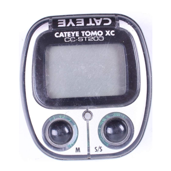
CATEYE TOMO XC
CYCLOCOMPUTER
Model CC-ST200
[with Heavy Duty Wire]
Fig.1
sensor band B
rubber pad
sensor band A
parallel
screw
markingline
of sensor
center of
magnet
outer cable
spiral tube
nyron ties
wire
bracket
rubber pad
L(cm)
TIRE SIZE
150
26 x 1.40
175
26 x 1.50
178
26 x 1.75
179
26 x 1.95
191
26 x 2.00
189
26 x 2.1
192
26 x 2.125
196
26 x 2.35
191
27 x 1
195
27 x 1-1/8
195
27 x 1-1/4
197
27 x 1-3/8
207
650 x 35A
210
650 x 38A
be shorter than this period.)
(Address for service)
2-8-25, Kuwazu, Higashi Sumiyoshi-ku, Osaka 546-0041 Japan
Service & Research Address for United States Consumers:
U.S. Pat. Nos. 4636769/4642606/5236759/5226340
CCMSTxch1-991124 Printed in Malaysia 066600035
1. Bracket
2. Wire
3. Sensor
4. Sensor Bands-A (S)(L)
5. Sensor Bands-B
6. Magnet
• The spokes must run correctly through the
inside the magnet as in fig.1.
• Attach the sensor with Sensor Bands-A-B to
the right fork. Choose a band that fits the fork
diameter (S size for up to 24ø, L for
oversize). If the front fork is thick, use the
longer screw.
1. Insert the band-B into the slit of the band-
A, and put the rubber pad inside of the
band-A(fig. 2). Adjust the length in order
that the screw-fastening part of the bands
are parallel when mounted to the fork(fig.
3). *To pull out the band B from band A,
tug strongly.
2. Mount the adjusted bands to the fork along
with the sensor, by temporarily tightening
the screw(fig. 4).
3. Align the magnet's center and the sensor's
Fig.3
marking line(fig. 5), and make sure of
2mm clearance between the magnet and
sensor (fig. 6). Then tighten the screw
securely. Cut the excess of the band-B
with a nipper or the like.
• Secure the wire with nylon ties as shown in
fig. 7. Wind the wire round the outer cable
and wrap these wires with the spiral tube.
Adjust the length of the wire. Loosen the wire
in the area marked with the arrow so that the
wire does not hinder handlebar operation.
• Use either 1mm- or 2 mm-thick pads if
necessary, according to handlebar diameter.
Fig.5
Attach the bracket close to the handlebar
stem (fig. 8).
• Slide main unit onto the bracket from front
until it clicks into position. To remove, pull it
off forward while pushing down the lever. (fig.
9)
•Test
Mount main unit. If main display does not show
any figures, press either M button or S/S button
to release from power saving function. Spin the
wheel to check if sensor pulse symbol flashes.
If not, adjust relative positions of magnet and
sensor following the instructions.
Fig.7
Slide the main unit onto the bracket from
front until it clicks into position. To remove
it, pull it off forward while pushing down the
lever. (Fig.9)
Attn.: CAT EYE Customer Service Section
Phone : 303-443-4595
Fax
: 303-473-0006
#169-9751
Attachment Kit (For TOMO XC)
#169-6180
Lithium Battery(CR1620)
Copyright© 1999 CATEYE Co., Ltd.
7. Sensor Band Rubber Pad
8. Bracket Rubber Pad (2 pcs.)
9. Nylon Tie (3 pcs.)
10. Sensor Band Screw (S)(L)
11. Spiral Tube
L(cm)
TIRE SIZE
200
650 x 38B
199
700 x 18C
202
700 x 19C
205
700 x 20C
206
700 x 23C
207
700 x 25C
207
700 x 28C
208
700 x 30C
215
700 x 32C
216
700C Tubular
216
700 x 35C
217
700 x 38C
209
700 x 44C
212
CAT EYE Service & Research Center
1705 14th St. 115 Boulder, CO 80302
Toll Free: 800-5CATEYE
e-mail: CatEyeUSA@aol.com
and Design Patented
3
lever
Fig.9
L(cm)
211
207
209
209
210
211
214
217
216
213
217
218
222
CO.,LTD.
Advertisement
Table of Contents

Related Manuals for Cateye TOMO XC


Summary of Contents for Cateye TOMO XC
- Page 1 Bracket Sensor Kit for Extra Large Fork #169-6168 Bracket Sensor Kit for Aero Bar #169-6167 Center Mount Bracket Kit #169-6169 Stem Mount Bracket Kit #169-9750 #169-9751 Attachment Kit (For Heavy Duty Wire) Attachment Kit (For TOMO XC) #166-5120 #169-6180 Wheel Magnet Lithium Battery(CR1620)
- Page 2 OPERATING INSTRUCTIONS TOMO XC A. Main Display (Speed) B. Sensor Pulse Symbol C. Mode Symbol D. Speed Scale Symbol E. Auto Mode Symbol F. Sub-Display (Selected Function) G. M (Mode) Button H. S/S (Start/Stop) Button I. Set Button J. Battery Case Cover K.
Need help?
Do you have a question about the TOMO XC and is the answer not in the manual?
Questions and answers