Table of Contents

Summary of Contents for Ros PT-10
- Page 1 UNDERWATER PAN AND TILT MODEL PT-10 OPERATING AND MAINTENANCE MANUAL SERIAL NUMBER: __________ SALES ORDER: __________ 5618 Copley Drive San Diego, CA 92111-7902 TEL (858) 565-8500 FAX (858) 565-8808 www.rosys.com 21-00019 REV B...
- Page 2 This warranty shall be governed by the laws of the State of California. In the event the defect is determined to be within the terms of this warranty, then ROS agrees to repair and/or replace (at ROS's discretion) the product or defective portion at no charge to the Purchaser.
-
Page 3: Customer Assistance
CUSTOMER ASSISTANCE ROS, Inc. uses a worldwide network of stocking distributors and representatives who are familiar with our products and are able to provide assistance during installation and/or operation of these products. If you have any questions or problems with this product that are not covered by this manual or instruction, please contact our agent in your area, or contact us directly by phone, fax or e-mail. -
Page 4: Change Record
CHANGE RECORD General Update to New Format 15APR97 Updated to a Standard PT-10 Manual 26MAR01 Added Quad Seal & Sealscrew Replacement to the “Seal Replacement” Section 28JUN05 Add configuration -02 (MHDL-12-FCR CONN) 02SEPT08 21-00019 REV B... -
Page 5: Table Of Contents
TABLE OF CONTENTS SECTION PAGE WARRANTY CUSTOMER ASSISTANCE CHANGE RECORD INTRODUCTION GENERAL DESCRIPTION SPECIFICATIONS STANDARD CONNECTOR WIRING INSTALLATION AND OPERATION Operational Check Installation Equipment Mounting Interconnection MAINTENANCE Fluid Volume Check Work Area Preparation End Cap Removal Seal Replacement Motor Removal and Replacement End Cap Replacement APPENDIX 21-00019 REV B... -
Page 6: Introduction
INTRODUCTION This publication describes the ROS model PT-10 Pan and Tilt which is available in two standard models; an air-filled version for nuclear and other shallow water applications, and an oil-filled pressure compensated unit for deep-water applications. For any problems or questions not covered in this manual, please contact the factory or one of our authorized representatives. -
Page 7: General Description
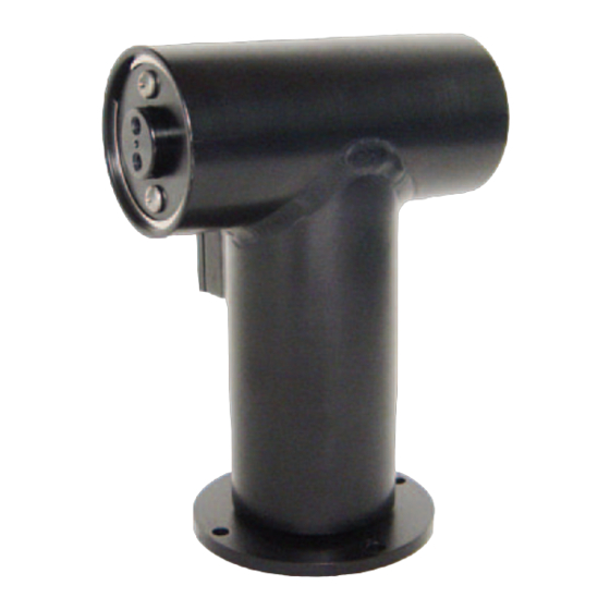
GENERAL DESCRIPTION The model PT-10 Pan and Tilt is designed to remotely orient underwater or in-air TV and photographic cameras, lights, acoustic equipment, and other instrumentation. The housing, end plates, and all machined internal components of the PT-10 are made of stainless steel, titanium or 6061-T6 aluminum which, is hard anodized for corrosion protection. -
Page 8: Pt-10 Specifications
PT-10 SPECIFICATIONS POWER: 120 VAC, 0.135 amp OPERATING DEPTH: AIR-FILLED 100 ft. (30.48 m) OIL-FILLED 9842.5 ft. (3000 m) LENGTH: 7.6 inches (193 mm) WIDTH: 5.8 inches (147mm) DEPTH (w/connector): 4.0 inches (101mm) WEIGHT IN AIR: AIR-FILLED: 6.5 lbs. (2.9 kg) 10.8 lbs. -
Page 9: Standard Connector Wiring
PAN RIGHT PAN CW 120 VAC PAN LEFT PAN CCW NOTE: Function directions are for a PT-10 mounted with the pan axis down. If inverted, the directions will be reversed. Bulk head Connector Configuration -01: LPMBH-5-MP (Face View) Face mount Connector... -
Page 10: Installation And Operation
INSTALLATION AND OPERATION When you receive the model PT-10 Pan and Tilt unit, unpack it carefully and inspect for any shipping damage or if oil-filled, oil leakage. Please contact the factory immediately if any such damage is noted. OPERATIONAL CHECK After unpacking the PT-10, an operational check should be made prior to installation of the unit. -
Page 11: Equipment Mounting
POWER OFF, lubricate the connector lightly with silicone spray, push together, and move the retaining strap on the mating connector into position. The opposite end of the cable attaches to a controller such as the ROS model PTC-2,or equivalent controller which provides the required power to the connector pins. Cable length and conductor size should be chosen such that a voltage of at least 100 VAC will be maintained at the pan and tilt while in operation. -
Page 12: Maintenance
WORK AREA PREPARATION Any work done on the internal parts of the PT-10 requires the unit to be opened. A clean work area should be prepared to avoid getting dirt or other particles on the seals or sealing surfaces, or inside the motor or precision harmonic gearing. -
Page 13: End Cap Removal
Refill the unit with fluid. NOTE: If water leakage has occurred and you suspect it may be caused by a worn output shaft seal, please contact ROS, Inc. for assistance. Replacement of these seals requires 21-00019 REV B... -
Page 14: Motor Removal And Replacement
MOTOR REMOVAL AND REPLACEMENT The motors used in the PT-10 are brushless 120 VAC synchronous motors, and are noted for very long lifetimes without maintenance. Before undertaking motor replacement, make sure that proper operating voltage is being provided by the controller and interconnecting cable. -
Page 15: End Cap Replacement
motor. NOTE: The position of the wave generator with respect to the motor shaft. Loosen the setscrews, which hold the wave generator to the motor shaft and remove this section of the gear mechanism. Remove the three flat head screws, which attach the motor plate to the motor assembly. - Page 16 fluid may be ejected through the seal screw holes, place a towel over the end cap to reduce the losses. Push the end cap down until the O-ring is at the snap ring grove. Replace the seal screws. Continue to press the end cap/shaft assembly in the housing bore and slowly push it into the housing.
-
Page 17: Appendix
APPENDIX PT-10 DRAWINGS 21-00002 Installation Drawing, PT-10 21-00000 Assembly, PT-10-Air-Al 21-00001 Assembly, PT-10-Air-SS 21-01000 Assembly, PT-10-Oil-Al 21-01001 Assembly, PT-10-Oil-SS 21-00003 Wiring Diagram, PT-10 21-00019 REV B...
Need help?
Do you have a question about the PT-10 and is the answer not in the manual?
Questions and answers