
Related Manuals for Aulisa Guardian Angel Rx Guardian Angel Rx Lite GA2000 Series


Summary of Contents for Aulisa Guardian Angel Rx Guardian Angel Rx Lite GA2000 Series
- Page 1 Guardian Angel ® Guardian Angel ® Rx Lite GA2000 Series Digital Vital Sign Monitoring System Instructions For Use ____________________________________________________________ 7MN00022-02...
-
Page 2: Disclaimer
Technologies, Inc. reserves the right to make changes and improvements to this manual and the products described within at any time, without notice or obligation. References to “Aulisa” in this manual shall imply Taiwan Aulisa Medical Devices Technologies, Inc. Aulisa is a registered trademark of Taiwan Aulisa Medical Devices Technologies, Inc. -
Page 3: Table Of Contents
Wi-Fi Network Reset .................... 27 Device Pairing ....................... 28 Automatic Pairing (Guardian Angel® Rx only) ............28 Pairing with a new Aulisa sensor module ............28 Pairing with a new Receiver/Transponder ............29 Device Verification ....................... 31 Verify the device function ..................31 Verify the alarm function BEFORE each use ............ - Page 4 FCC Compliance ......................48 Service, Support, and Warranty ................... 50 Specifications ....................... 51 Parts and Accessories ....................53...
-
Page 5: Guide To Symbols
Guide to Symbols Single Use MR Unsafe: must not be used in an MRI environment. - Page 6 Date of Manufacture...
-
Page 7: Welcome
Display Unit/Aulisa mobile application and the Receiver/Transponder which are intended for use in conjunction with a variety of Aulisa sensor module(s). Refer to the Instructions for Use of Aulisa sensor module(s) for detailed instructions. Adult/Pediatric Oximeter Module: 7MN00023-02 ... -
Page 8: Ga2000 Series Function
It is intended for adults, pediatrics, and infants. GA2000 Series Function The Aulisa sensor module(s) detects vital signs and sends out the data to the Receiver/Transponder using Bluetooth technology. The Receiver/Transponder then transmits, via a customer Wi-Fi network, the physiological data along with audio/video signals obtained by an embedded camera to the Display Unit or Aulisa mobile application for display. -
Page 9: Ga2000 Series Intended Use
GA2000 Series Intended Use GA2000 Model GA2000 of Guardian Angel Rx / Guardian Angel Rx Lite GA2000 Series Digital Vital Sign Monitoring System is indicated for use in measuring, recording, and displaying functional oxygen saturation of arterial hemoglobin (SpO2) and pulse rate (PR). - Page 10 continuous monitoring of SpO2 and PR of adults and pediatrics during non-motion and under well-perfused conditions. The Thermometer Module is indicated for continuous armpit body temperature monitoring of adults, pediatrics, and infants. GA2101 Model GA2101 of Guardian Angel Rx / Guardian Angel Rx Lite GA2000 Series Digital Vital Sign Monitoring System is indicated for use in measuring, recording, and displaying functional oxygen saturation of arterial hemoglobin (SpO2) and pulse rate (PR) and body temperature.
-
Page 11: Precautions For Use
Do not use in or around water or any other liquid when AC power adaptor is used. Only use this device with charging adaptors provided by Aulisa. Do not immerse any part of the device in any liquids. 10. Do not subject the device to extreme hot or cold temperatures, humidity, or direct sunlight. - Page 12 would result in loss of data transfer. Alarm notifications will be triggered for such failure. 15. It is recommended that the system works on an independent Wi-Fi network and always use the Wi-Fi network with WPA2-PSK security to ensure the data safety.
-
Page 13: Device Components
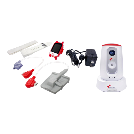
Device Components Display Unit Aulisa mobile application (“Aulisa Lite GA1000”) *Smartphone not included. Receiver/Transponder Display Unit Stand Receiver/Transponder Display Unit Charging Adapter (Type-C) Charging Adapter Receiver/Transponder Clamp Receiver/Transponder Velcro Strap... -
Page 14: Device Overview
It can receive audio messages sent from the Receiver/Transponder. The Aulisa mobile application provides both iOS and Android version and serves as a substitute for the Display Unit when installed on personal mobile devices. Please download “Aulisa Lite GA1000”... - Page 15 RESTORE DEFAULTS Restore defaults of alarm setting Setting Item Description Enter a serial number of Aulisa sensor module(s) either Module Pairing by scanning the QR code or by key in the number manually. Adjust the alarm upper limit and lower limit of each Alarm Setting parameter.
-
Page 16: Display Unit
Receiver/Transponder. The Display Unit is pre-installed with Aulisa application. NOTE: It is recommended that the Display Unit be placed on the Display Unit Stand. - Page 17 When the vital signs cannot be measured, the dashes “- - No data -” shows in each of the vital sign windows. Bluetooth The icon turns blue when connection status system pairing succeeds. This icon indicates whether there is a finger inserted in the adult/pediatric oximeter Measurement site module.
- Page 18 These icons indicate the battery level of Aulisa sensor Battery Level of module(s) at Full, Medium, Aulisa sensor or Low. module(s) A medium priority system alarm will be displayed when the battery level is low. This icon indicates whether there is a connection...
- Page 19 Tap on this button to return Screen to the previous page. In the Setting menu, tap on this button to change the Wi- network of the Aulisa- CONNECTION Connection Setup developed Application or of the Receiver/Transponder, and to modify the password for the Receiver/Transponder.
- Page 20 Brightness brightness of the display. In the Setting menu, tap on this button to adjust the alarm limits for each Aulisa sensor module. ALARM SETTING Set Alarm Limits NOTE: The alarm limits are adjustable only when the wireless connection is established.
- Page 21 The button appears when the Infant Oximeter Module is detached from the foot. STANDBY Standby Tap on the button to return to the “Before You Start” page.
-
Page 22: Receiver/Transponder
Bluetooth, integrates audio and video of the person being monitored , and then converts the data to Wi-Fi signals, which are transmitted to and displayed by the Aulisa mobile application. The Aulisa sensor module(s) must be used within 32.8 feet (10 meters) to the Receiver/Transponder. -
Page 23: Audio/Video Feature
Audio/Video Feature Video: View monitoring video Listening: Tap to turn on and receive monitoring audio Talking: Press and hold to send an audio message... -
Page 24: Device Setting Up
Before you begin your monitoring session, unpack the Display Unit (Guardian Angel® Rx only) and Receiver/Transponder and become familiar with their parts. For Guardian Angel® Rx Lite users, please download the Aulisa mobile application from Google Play or App Store before use. - Page 25 Secure the power cable to the Holder with Velcro strap. Hang on the wall Slide the Clamp into the Holder. Hang the Holder on the wall. Ensure the Holder is secure. Place the Receiver/Transponder body on the Holder. Secure the power cable to the Holder with Velcro strap.
- Page 26 The power LED will light green when the power is on. Step 4: Enable the Display Unit or Aulisa mobile application. If you’re using the Display Unit, follow Step 5 and 6 to power the device; if you’re using Aulisa mobile application, follow the onscreen instructions to complete the system setup.
-
Page 27: Device Connection
“RESET” is heard. Step 4: Select a secure customer Wi-Fi network from the list of available connections displayed on the Display Unit/Aulisa mobile application (for Android user), or key in the network name (for iOS user). Enter the network security password and press “CONFIRM”. -
Page 28: Wi-Fi Network Reset
(for iOS user). Enter the network security password and press “CONFIRM”. For Receiver/ Transponder NOTE: The Wi-Fi network of the Display Unit/Aulisa mobile application will be changed as that of the Receiver/Transponder changes. Step 1: Tap on “SETTING” → “CONNECTION” → “RECEIVER/TRANSPONDER” → “CONFIRM”. -
Page 29: Device Pairing
The power LED on the Aulisa sensor module(s) lights green when the power is Step 2: In the Setting menu, select “PAIRING" → “SENSOR MODULE”. Step 3: Scan the QR Code or key in the serial number located on the Aulisa sensor module(s). -
Page 30: Pairing With A New Receiver/Transponder
NOTE: The alarm event history is managed via the Receiver/Transponder, so you won’t be able to see the current alarm event history when the Display Unit/Aulisa mobile application is paired to a new Receiver/Transponder. Step 1: Ensure the designated Receiver/Transponder is turned on. Wait until the Wi- Fi Link LED lights red. - Page 31 NOTE: Beware of connecting to an unsecured network provides no security and exposes all your network traffic. NOTE: Ensure the customer Wi-Fi Network connection has a strong and reliable signal. NOTE: The Wi-Fi Link LED on Receiver/Transponder will turn solid red, indicating the Wi-Fi connection has been established.
-
Page 32: Device Verification
Step 1: Set up the system. Refer to the Aulisa sensor module(s) Instructions for Use for setting up instructions. Step 2: Make sure Aulisa sensor module(s) is worn on or attached to the right place firmly. Step 3: Verify that the Bluetooth connection status icon on the screen is blue and the status indicator on Aulisa sensor module(s) is blinking green. -
Page 33: Device Power Off
Device Power Off Display Unit Step 1: Press the Power button for at least three (3) seconds until a message displayed. Step 2: Choose “Power off” to turn off the Display Unit. NOTE: You may also tap on the “SLEEP” button to enter the sleep mode. Receiver/Transponder Press and hold the Power button for at least three (3) seconds to turn off the Receiver/Transponder. -
Page 34: Receiver/Transponder
NOTE: The charging LED indicator lights blue during charging and goes off when fully charged. NOTE: The battery low LED indicator lights yellow when low battery. CAUTION!!! Only use adaptors supplied or manufactured by Taiwan Aulisa Medical Devices Technologies, Inc. -
Page 35: Alarms And Limits
Alarms and Limits Alarm Features The GA2000 Series provides high and medium priority audible and visual alarms. The visual alarm is indicated by the alarm window on the screen. Audio alarms will sound from the device speaker. NOTE: The volume for high priority alarms cannot be adjusted on the Display Unit. High Priority Alarms High priority alarms are those that require immediate attention to the person being monitored, including SpO... - Page 36 High priority audio alarms are: 3 beeps, short pause, 2 beeps, short pause, 3 beeps, short pause, 2 beeps, and 5-second pause. This sequence repeats until the alarm is cleared or silenced. Tap on ʻʻPAUSE AUDIOʼʼ button to pause the alarm audio for 2 minutes. Tap on ʻʻAUDIO OFFʼʼ...
- Page 37 Limit (More Than Half A Minute) screen. Aulisa sensor module(s) BLE Disconnected Receiver/Transponder Wi-Fi Disconnected Medium priority audio alarms are: 3 beeps and 25-second pause. This sequence repeats until the alarm is cleared or silenced.
- Page 38 Multiple Alarms When there are high and medium priority alarms triggered simultaneously, the system will display all the alarm text messages but will only sound the high priority alarm. CAUTION!!! Silencing alarms does not mean the situation has been resolved. CAUTION!!! Tapping on “AUDIO OFF”...
-
Page 39: Alarm Limits
Follow the instructions below to review or set alarm limits. Step 1: Ensure the system connection (Bluetooth/Wi-Fi) is established. (See “Device Connection” and “Device Pairing” sections.) Step 2: Tap on "SETTING" button on the MAIN screen, and then tap on “ALARM LIMITS” button. Select the designated Aulisa sensor module. - Page 40 NOTE: Alarm limits can be adjusted only when the Aulisa sensor module(s) is paired. NOTE: In an alarm event, ʻʻALARM LIMITSʼʼ button will appear after you select "AUDIO PAUSE" button or "AUDIO OFF" button. Step 3: To turn alarms on or off, tap on ʻʻON/OFFʼʼ button. (Turn on the alarm before adjusting the value.)
- Page 41 NOTE: max limit is turned off by default. NOTE: There is no alarm setting for pulse amplitude. NOTE: TEMP min limit is turned off by default. NOTE: Select designated Unit of TEMP, °C or °F, before adjusting the alarm limits. CAUTION!!! A potential hazard exists if different alarm presets are used for the same or similar equipment in any single area.
- Page 42 NOTE: The minimum alarm limit cannot exceed the maximum alarm limit, even if the maximum alarm limit is turned off. For example, if the maximum SpO limit is turned off but was previously set at 90%, the minimum SpO limit cannot be set higher than 90%.
-
Page 43: Care And Maintenance
Receiver/Transponder will cause damage and void the warranty. If the Display Unit or Receiver/Transponder is not functioning properly, see “Troubleshooting” section for more information. For care and maintenance of Aulisa sensor module(s), refer to the Aulisa sensor module(s) Instructions for Use for additional instructions. -
Page 44: Troubleshooting
Aulisa by going online at www.aulisa.com under "Contact Us". CAUTION!!! This system is a precision electronic instrument and must be repaired by knowledgeable and specially trained Aulisa personnel only. Do not attempt to open the case or repair the electronics. -
Page 45: Manufacturer's Declaration
Manufacturer’s Declaration Refer to the following table for specific information regarding compliance to IEC 60601-1-2 for Display Unit. *For all EQUIPMENT and SYSTEMS Guidance and Manufacturer's Declaration - Electromagnetic Emission This device is intended for use in the electromagnetic environment specified below. The customer and/or user of this device should ensure that it is used in such an environment. - Page 46 *For all EQUIPMENT and SYSTEMS Guidance and Manufacturer's Declaration - Electromagnetic Immunity This device is intended for use in the electromagnetic environment specified below. The customer and/or user of this device should ensure that it is used in such an environment. IEC 60601-1-2 test Electromagnetic Immunity test...
- Page 47 *For EQUIPMENT and SYSTEMS that are not LIFE-SUPPORTING Guidance and Manufacturer's Declaration - Electromagnetic Immunity This device is intended for use in the electromagnetic environment specified below. The customer and/or user of this device should ensure that it is used in such an environment. IEC 60601-1-2 Electromagnetic environment Immunity test...
- Page 48 abnormal performance is observed, additional measures may be necessary, such as reorienting or relocating the device. b. Over the frequency range 150 kHz to 80 MHz, field strengths should be less than [3] V.
-
Page 49: Fcc Compliance
FCC Compliance Declaration of Conformity with FCC for Electromagnetic Compatibility This device complies with Part 15 of the FCC Rules. Operation is subject to the following two conditions: (1) this device may not cause harmful interference, and (2) this device must accept any interference received, including interference that may cause undesignated operation. - Page 50 methods and procedures specified in OET Bulletin 65 Supplement C. The highest reported SAR for the device is 0.116 W/kg. When suing IEEE 802.11a wireless LAN, this product is restricted to indoor use, due to its operation in the 5.15 to 5.25GHz frequency range. The FCC requires this product to be used indoors for the frequency range of 5.15 to 5.25GHz to reduce the potential for harmful interference to co channel mobile satellite systems.
-
Page 51: Service, Support, And Warranty
Aulisa's place of repair as designated by Aulisa, and Aulisa is responsible for the cost of delivery back to the purchaser. Aulisa reserves the right to charge a fee for a warranty repair request on an Aulisa product that is found to be within... -
Page 52: Specifications
Specifications Display Unit (Guardian Angel® Rx only) Display Panel 10.1” IPS Touch Panel Power Requirements Mains 100-240V AC 50-60 Hz DC Input 5V DC/AC adaptor Internal Power Battery Type 3.8V battery Battery Life 2 hours of continuous operation Dimensions 7.04” x 10.35” x 0.46” (179mm x 263mm x 11.8mm) Weight 21.87 oz (620g) - Page 53 Range 32.8 feet (10 meters) spherical radius Protocol Bluetooth 4.0 Direction Bi-direction Data rate Up to 100kbps Wi-Fi Protocol 802.11 b/g/n/ac, 2.4GHz/5GHz Direction Bi-direction Classifications per IEC 60601- 1 Type of Protection Class II, MOPP (on AC power) Internally powered (on battery power) Type of Protection Type BF-Applied Part Mode of Operation...
-
Page 54: Parts And Accessories
GA-RT0001 Charging Adaptor - Receiver/Transponder GA-CR0001 *for Guardian Angel® Rx only Refer to the Aulisa sensor module(s) Instructions for Use for more Aulisa sensor module(s) information. You may also contact your distributor or contact Aulisa by going online at www.aulisa.com under "Contact Us".
Need help?
Do you have a question about the Guardian Angel Rx Guardian Angel Rx Lite GA2000 Series and is the answer not in the manual?
Questions and answers