Table of Contents
Advertisement
Quick Links
Advertisement
Table of Contents

Related Manuals for network SDI-OE-2


Summary of Contents for network SDI-OE-2
- Page 1 SDI-OE-2 Dual SDI Optical to Electrical Converter Product Manual Rev. 0...
-
Page 2: Revision History
SDI-OE-2 Rev. 0 Network Electronics ASA Thorøya P.O. Box 1020 Sandefjord, Norway Phone: +47 33 48 99 99 Fax: +47 33 48 99 98 E-mail: support@network-electronics.com www.network-electronics.com Service Phone: +47 90 60 99 99 Revision history Current revision of this document is the uppermost in the table below. -
Page 3: Table Of Contents
SDI-OE-2 Rev. 0 Contents Revision history ................2 1 Product overview ................4 2 Specifications................. 5 2.1 Optical input ....................5 2.2 Electrical ......................5 2.3 Electrical output....................5 2.4 Standards ....................... 5 3 Configuration ................. 6 3.1 Format configuration ..................6 3.2 Configuration examples ................. -
Page 4: Product Overview
HD-OE-2 the first choice for all optical transport demands. The SDI-OE-2 can transport all SD signal formats in addition to DVB-ASI and SMPTE 310. It performs optical refreshing and signal reclocking, which is selectable on application. The optical input comes with a sophisticated PIN diode with a sensitivity typically better than –30dBm operating in the 2... -
Page 5: Specifications
SDI-OE-2 Rev. 0 2 Specifications 2.1 Optical input Data rate optical: 19.4 – 540 Mbps. Sensitivity: Better than -25dBm Detector overload threshold: Min. 0dBm Optical wavelength: and 3 optical window, 1200 - 1600nm. Transmission circuit fiber: Single Mode 9/125um, Multi Mode 9/125um compatible. -
Page 6: Configuration
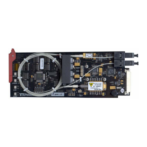
The SDI-OE-2 can support a number of different broadcast formats. The correct configuration can either be set with a DIP switch or with the GYDA Control System. The layout of SDI-OE-2 is shown in the drawing below with the DIP switch to the upper left position. -
Page 7: Configuration Examples
Figure 3: Normal operation. Signal on input 2 not present. Change over. Priority on input 2 Change over. Priority on input 2 Figure 4: Change over operation. Priority on input 2. Los of signal on input 2. SDI-OE-2 will switch back to input 2 when signal is present. -
Page 8: Connector Module
Figure 5: Connector module for SDI-OE-2. In typical use a SDI-EO-2 / SDI-OE-2 module at each end will be used. Two channels simultaneously can be converted from optical to electrical channels The electrical input signal is connected to the INx input on the transmitting SDI-EO-2, and the electrical output is connected to corresponding the OUTx+ or OUTx- output BNC on the receiving SDI-OE-2. -
Page 9: Terminal Format Support
Alarms ∗ SDI-OE-2 has a “Transparent mode”. In this mode all reclockers are switched off and no jitter attenuation will be performed. This mode may be used for non-standard or unsupported bit rates over shorter distances and up to 1 Gbps. -
Page 10: Module Status
These outputs can be used for wiring up alarms for third party control systems. The GPI outputs are open collector outputs, sinking to ground when an alarm is triggered. The GPI connector is shown in figure below. SDI-OE-2 module GPI pinning: Signal Name... -
Page 11: Front Panel - Status Monitoring
The LED’s are visible through the front panel as shown in the figure below. Figure 7: Front panel indicators for the SDI-OE-2. The SDI-OE-2 has 4 LED’s each showing a status corresponding to the GPI pinning. Diode \ State Red LED... -
Page 12: Laser Safety Precautions
SDI-OE-2 Rev. 0 6 Laser safety precautions Guidelines to limit hazards from laser exposure. All the available EO units in the flashlink range include a laser. Therefore this note on laser safety should be read thoroughly. The lasers emit light at 1310 nm or 1550 nm. This means that the human eye cannot see the beam, and the blink reflex cannot protect the eye. -
Page 13: General Environmental Requirements For Flashlink ® Equipment
SDI-OE-2 Rev. 0 ® General environmental requirements for flashlink equipment 1. The equipment will meet the guaranteed performance specification under the following environmental conditions: - Operating room temperature range: 0°C to 40°C - Operating relative humidity range: < 90% (non-condensing) 2. -
Page 14: Certificate Of Conformity
SDI-OE-2 Rev. 0 Certificate of Conformity Network Electronics ASA Company Registration Number: N-3204 Sandefjord NO 976 584 201 MVA Norway Declares under sole responsibility that the product: Product Name: SDI-OE-2 Product Description: Dual SDI Optical to Electrical Converter To which this declaration relates are of Norwegian origin and are in conformity with the... -
Page 15: Product Warranty
SDI-OE-2 Rev. 0 Product Warranty The warranty terms and conditions for the SDI-OE-2 follow the General Sales Conditions by Network Electronics ASA. These conditions are available on the company web site of Network Electronics ASA: www.network-electronics.com...