
Summary of Contents for MESSKO MZT1650S
- Page 1 MZT1650S Messko calibration bath www.messko.com Operating Instructions BA2112/00/01...
- Page 2 1 Device Description and Intended Use BA 2112/00/01...
-
Page 3: Table Of Contents
1 Device Description and Intended Use 0 Table of Contents Page 1 Device Description and Intended Use ......................4 2 Safety Instructions ............................6 2.1 Qualified personnel ..........................6 2.2 Basic safety regulations ........................6 2.3 Safety instructions for the application of calibration liquids .............. -
Page 4: Device Description And Intended Use
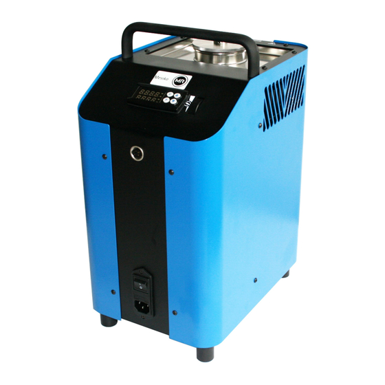
1 Device Description and Intended Use 1 Device Description and Intended Use The Messko calibration bath is a portable unit for service tasks and is intended to inspect thermometers, thermostats and resistance thermometers. The operational safety of the supplied instrument is only guaranteed if it is operated according to his intended use (inspection of temperature sensors). - Page 5 The Messko calibration bath also has a thumb wheel for controlling the stirring speed. A power supply switch is located on the front of the housing. This is also where the IEC plug with fuse for the mains supply can be found.
-
Page 6: Safety Instructions
Even though Messko provides assistance for the use of the product through personal consultation or the respective documents, it is the responsibility of the customer to determine the suitability of the product for the specific application. -
Page 7: Safety Instructions For The Application Of Calibration Liquids
Prior to transport or contact with the metal block / liquid bath ensure that it has cooled down sufficiently, otherwise there is a risk of severe burns caused by the metal block / liquid bath and the test specimen. If problems or questions arise, please contact Messko directly. BA 2112/00/01... -
Page 8: Unpacking And Inspecting The Delivery
- Sensor cage - Carrier for up to 5 sensors - Magnetic stirrer - Mains connection cable - 1 liter silicone oil (10CS) (Messko Art. no. 649-000-001) - Bilge pump - Test certificate - Operating Instructions - Service and transport case 4 Description of the Controls 4.1 Front of the controller... - Page 9 4 Description of the Controls 3 - key - Increasing the setting values - Selecting individual menu items - Returning to the previous menu level 4 – U key - Retrieving the saved set temperatures 5 - LED OUT 1 - Signals the status of the output for the temperature control If the LED OUT 1 lights up, the calibration bath is heating If the LED OUT 1 does not light up, the calibration bath is not heating...
-
Page 10: Start-Up Of The Calibration Bath
5.2.1 Characteristics of the calibration liquid Different calibration liquids supply varying calibration results due to their specific characteristics. The Messko calibration bath is adjusted on the silicon oil shown below. We recommend the following calibration liquid for the specified temperature range:... -
Page 11: Filling The Calibration Bath
5 Start-up of the Calibration Bath 5.2.2 Filling the calibration bath Remove the transport cover. Insert the test specimen into the sensor cage. Fill the tank with calibration liquid. The max. filling level in the tank is displayed by the upper edge of the aluminium lining (see Fig. -
Page 12: Testing Temperature Sensors
5 Start-up of the Calibration Bath 5.2.3 Operating the magnetic stirrer The best possible homogeneity is achieved by stirring the calibration liquid with the magnetic stirrer. Set the stirring speed to the respective max. speed. Turn the thumb wheel (Fig. 6) upwards to increase and downwards to decrease the stirring speed. -
Page 13: Reference And Set Temperature Display
5 Start-up of the Calibration Bath 5.6 Reference and set temperature display Upper display (red): The red, 4-digit, 7-segment display shows the current temperature of the metal block / liquid bath. Lower display (green): The green, 4-digit, 7-segment display shows the current set temperature of the metal block / liquid bath. Once the set temperature has been achieved, the radiated heat energy from the metal block / liquid bath is supplied by short firing pulses, thus ensuring that the temperature inside is kept constant. -
Page 14: Operating The Calibration Bath
6 Operating the Calibration Bath 6 Operating the Calibration Bath Three operating modes are available: Calibration mode This is the normal operating mode in which the inspection of test specimens is carried out. Set value mode The set temperatures can be entered in this mode. ... -
Page 15: Setting A Temporary Set Temperature (Set Value Mode)
6 Operating the Calibration Bath 6.2 Setting a temporary set temperature (set value mode) In this operating mode it is possible to temporarily modify a saved set temperature. Press the P key. The currently active set value memory, e.g. SP 2 (set point 2), is displayed by the upper display (red). -
Page 16: Programming (Main Menu)
6 Operating the Calibration Bath 6.3 Programming (main menu) All the settings can be carried out in this menu structure. Press the P key for approx. 5 seconds. The main menu opens. Use the and keys to select the desired main menu (see overview). ... - Page 17 6 Operating the Calibration Bath As displayed by the menu structure, it is possible to reach the group and parameter levels to carry out settings via OPEr. Fig. 14: Menu structure at group and parameter level Returning to another level If no key is pressed in the main menu at the group or parameter level for approx.
-
Page 18: Switching Off The Automatic Control
6 Operating the Calibration Bath 6.3.1 Switching off the automatic control For certain tasks it can be advantageous to switch off the control, e.g. to carry out settings at the calibration bath. Press the P key when in calibration mode for approx 5 sec., the main menu opens. OPEr appears on the upper display (red) LED SET flashes on the lower display (green). -
Page 19: Switching On The Automatic Control
6 Operating the Calibration Bath 6.3.2 Switching on the automatic control The control is switched off if the following display appears: An alternating display of the current reference temperature and OFF appears on the upper display (red). The current set temperature appears on the lower display (green). Fig. -
Page 20: Switching On The Manual Control
6 Operating the Calibration Bath 6.3.3 Switching on the manual control It is possible to switch off the automatic control of the calibration bath and to achieve the desired temperature via manual control. Press the P key for approx 5 sec., the main menu opens. OPEr appears on the upper display (red). -
Page 21: Switching Off The Manual Control
6 Operating the Calibration Bath 6.3.4 Switching off the manual control The manual control is switched on if the following display appears: The current reference temperature appears on the upper display (red). The letter H and the currently set output capacity in % appear on the lower display (green). Fig. -
Page 22: Setting And Saving Fixed Set Temperatures
6 Operating the Calibration Bath 6.3.5 Setting and saving fixed set temperatures In order to save set temperatures in the calibration bath, the respective set value memory has to be opened. Press the P key for approx 5 sec. when in calibration mode, the main menu opens. OPEr appears on the upper display (red). - Page 23 6 Operating the Calibration Bath Press the P key to open the respective set value memory. The selected set value memory, e.g. SP 3 flashes on the upper display (red). The corresponding current set temperature appears on the lower display (green). Fig.
-
Page 24: Retrieving The Saved Set Temperatures
6 Operating the Calibration Bath 6.3.6 Retrieving the saved set temperatures The saved set temperatures can be retrieved in calibration mode. Press the U key for approx 2 sec., the current set value memory opens. The current reference temperature appears on the upper display (red). The set value memory SP1, SP2, SP3 or SP4 appears on the lower display (green) for 2 sec. -
Page 25: Setting A Gradient Control And A Temperature Profile
The heating capacity of the calibration bath is limited. Hence only such settings make sense which extend the time for achieving the set temperature (compared with the default setting). Calibrator type Setting for “SLor” (heating/cooling) MZT1650S with silicone oil 10CS < 3 °C/min BA 2112/00/01... - Page 26 The cooling gradient "SLor" is active if the reference temperature is higher than the set temperature. Only settings below the cooling capacity of the calibration bath have an effect on the cooling gradients. Messko calibration bath Setting for “SLoF” (heating/cooling)
- Page 27 6 Operating the Calibration Bath Press the P key again, the group level opens. OPEr appears on the upper display (red). SP appears on the lower display (green) and LED SET flashes. Fig. 32: Group Use the key to select the group rEG.
-
Page 28: Setting The Heating Gradient
6 Operating the Calibration Bath 6.3.7.1 Setting the heating gradient The heating gradient "SLor" is active if the reference temperature is lower than the set temperature. The setting range extends from 99.99 °C/min up to 0.00 °C/min. Caution! The function is deactivated if SLor = InF (In no Function) has been set. You are in the parameter level rEG appears on the upper display (red). -
Page 29: Setting The Cooling Gradient
6 Operating the Calibration Bath 6.3.7.2 Setting the cooling gradient The cooling gradient "SLoF" is active if the reference temperature is higher than the set temperature. The setting range extends from 99.99 °C/min up to 0.00 °C/min. Caution! The function is deactivated if SLoF = InF (In no Function) has been set. You are in the parameter level. -
Page 30: Setting The Duration Time
6 Operating the Calibration Bath Note: Press the and key to raise and lower the value by 0.1 respectively. If the keys are held pressed for at least one second, the value increases or decreases quickly and after two seconds even more quickly; this means the desired value can be reached rapidly. - Page 31 6 Operating the Calibration Bath Press the P key. dur.t flashes on the upper display (red). The respective currently set duration time appears on the lower display (green). Fig. 42: Duration time entry Press the key to increase the duration time dur.t. ...
-
Page 32: Error Messages
If servicing is required, shut down the calibration bath (see chapter 12) and return it to Messko. 8 Cooling Down of the Metal Block / Liquid Bath Caution! Risk of burns: Prior to transport or contact with the metal block / liquid bath ensure that it has cooled down sufficiently;... -
Page 33: Warranty And Repairs
10 Warranty and Repairs The Messko calibration bath is under guarantee for 12 months as from the date of delivery for construction errors or material defects. The guarantee is limited to repairs or replacing the calibration bath. Warranty shall not apply if the calibration bath is opened and unauthorized repair work is carried out or if the calibration bath is not used for its intended purpose or installed incorrectly. -
Page 34: Technical Data
13 Technical Data 13 Technical Data 13.1 Technical data Display range/Setting range -50.0 °C to +165.0 °C in 0.1 °C resolution Reference temperature setting range With silicone oil between -35 °C and 165 °C Block temperature control via PID controller via the P key and the... - Page 35 13 Technical Data Power supply 90…240 VAC +/- 10 %, 50/60 Hz Power consumption approx. 400 VA Fuse 6.3 A slow (for 90…240 VAC) Operating temperature 0...50 °C Moisture in the operating area 30...95 %rH not condensing Transport and storage temperature -10...60 °C Degree of protection IP 20...
-
Page 36: Heating And Cooling Periods
13 Technical Data 13.2 Heating and cooling periods Measuring conditions: All periods relate to a reference sensor Pt100/4, D = 6 mm, stainless steel casing The reference sensor is located 5 mm above the mesh insert in the middle of the tank ... - Page 37 13 Technical Data BA 2112/00/01...
- Page 38 13 Technical Data BA 2112/00/01...
- Page 39 13 Technical Data BA 2112/00/01...
- Page 40 ©Messko GmbH Telefon +49 (0)6171 6398-0 13 Technical Data Gewerbegebiet An den Drei Hasen Telefax +49 (0)6171 6398-98 Messko-Platz 1 info@messko.com 61440 Oberursel, Germany www.messko.com Important note: The information contained in all of our publications may differ in detail from the actual equipment delivered.
Need help?
Do you have a question about the MZT1650S and is the answer not in the manual?
Questions and answers