
Subscribe to Our Youtube Channel
Summary of Contents for FRIMEC FCR200-1400E
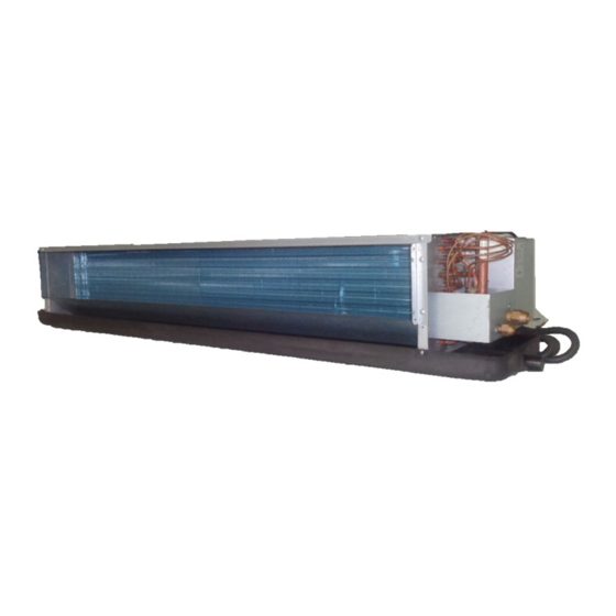
- Page 1 FAN COIL UNIT Models: FCR200-1400E FCRQ400-800B FCR200-1400B FFM800-3000B FF/FC550-1500A FKM600-1500A Air-Side Products FAS01-2016/17B...
-
Page 2: Table Of Contents
General Data ......................8 Operating Range ...................... 14 Sound Data ........................15 Sound Pressure Level ....................15 Dimensions ........................ 18 Wiring Diagrams ....................... 23 Installation ........................25 Servicing and Maintenance ....................33 Troubleshooting ........................ 34 © 2016 FRIMEC-INTERNATIONAL. All rights reserved. Page 1... -
Page 3: Product Nomenclature
Product Nomenclature Concealed Type Fan Coil Unit With filter No filter Bottom return air plenum Back return air plenum No return air plenum Standard drain pan Extended drain pan High static pressure (for FFM only) 30Pa static pressure 60Pa static pressure Left piping (facing supply air duct) Right piping (facing supply air duct) Product generation... - Page 4 Low Noise Concealed Type Fan Coil Unit FCRQ With filter No filter Bottom return air plenum Back return air plenum No return air plenum Standard drain pan Extended 200m Extended 400m Low static pressure 30Pa static pressure Left piping (facing supply air duct) Right piping (facing supply air duct) Product generation Unit size...
- Page 5 High Delta-T Ceiling Concealed Type Fan Coil Unit With return air plenum Without return air plenum Extended drain pan Standard drain pan High ESP Left piping (facing supply air duct) Right piping (facing supply air duct) Product generation 400 Unit size FCR High Delta T Fan Coil Unit Exposed Type Fan Coil Unit Product generation...
- Page 6 Cassette Type Fan Coil Unit Product Generation Unit size Cassette FCU Page 5...
-
Page 7: Features
Features Slim and Compact Design Light and rigid construction due to the compact and strong structural design of the unit. Slim unit design also fulfills the stringent space requirement of today’s building design. High Air Volume FCU with the height of only 430mm is most suitable for application that demand for high air flow but with space saving in mind. - Page 8 FCR / E FCRQ / B FCR / B Page 7...
-
Page 9: Engineering Specifications
Engineering Specifications General Data - Ceiling Concealed FCU (3 rows coil) 50/60Hz Model 200E 300E 400E 500E 600E 800E 1000E 1200E 1400E 1030 1380 1710 2040 2400 High 1006 1200 1412 1030 1290 1540 1975 Air Flow Medium 1160 1040 1255 High 2250... - Page 10 General Data - Low Noise Ceiling Concealed FCU 50/60Hz Model FCRQ 400B 500B 600B 800B 1020 1360 High 1030 Air Flow Medium High 4020 4850 6010 7950 Total Cooling Capacity Medium 3540 4070 5050 6670 2925 3200 4385 5570 High 2970 3485 4455...
- Page 11 General Data - High Delta-T Ceiling Concealed FCU (4 rows coil) 50/60Hz Model 200B 300B 400B 500B 600B 800B 900B 1000B 1200B 1400B 1150 1450 1620 2115 2445 2750 High 1244 1438 1618 1120 1410 1540 1980 2220 2580 Air Flow Medium 1518 1165...
- Page 12 General Data - High Air Volume FCU ( 4 rows coil) 50/60Hz 800BH 1000BH 1200BH 1600BH Model High Medium High Medium High Medium High Medium 1265 1015 1510 1215 1925 1540 1230 2490 1990 1595 Air Flow High ESP (H) 130 Pa 1132 1465...
- Page 13 General Data - Vertical Exposed FCU / Ceiling Exposed FCU (3 rows coil) 50/60Hz Model 550A 700A 900A 950A 1300A 1500A 1190 1510 1600 2210 2550 High 1300 1500 1020 1200 1360 1800 2200 Air Flow Medium 1060 1290 1000 1150 1600 1800...
- Page 14 General Data - Ceiling Cassette FCU 50/60Hz Model 600A 750A 850A 950A 1200A 1500A 1000 1250 1400 1600 2000 2550 High 1180 1500 1190 1060 1360 1700 2170 Air Flow Medium 1000 1280 1010 1150 1440 1840 1080 7270 8220 10390 Total Cooling Capacity High...
-
Page 15: Operating Range
Operating Range Operating Limits Maximum water-side pressure 2.0MPa Minimum entering water temperature 5°C Maximum entering water temperature 80°C Minimum air inlet temperature 5°C Maximum air inlet temperature 43°C Power supply 220-240V/1Ph/50Hz Page 14... -
Page 16: Sound Data
Sound Data Microphone 1000 Unit 1000 Unit Microphone (b) Horizontal Unit (a) Vertical Unit Sound pressure level test setup complies to GB/T19232-2003 Sound pressure level Model: FCR-E 30Pa 1/1 Octave Sound pressure level (dBA, ref 20µPa) Overall Model Fan Speed dB(A) High 36.9... - Page 17 Model: FCR-E 60Pa 1/1 Octave Sound pressure level (dBA, ref 20µPa) Overall Model Fan Speed dB(A) High 41.7 Medium 34.6 43.5 High Medium 34.8 28.4 High 46.3 37.9 Medium 29.1 High Medium 37.3 28.9 High 49.1 Medium 42.5 33.7 High Medium 42.3 34.5...
- Page 18 Model: FFM-BH 130Pa 1/1 Octave Sound pressure level (dBA, ref 20µPa) Overall Model Fan Speed dB(A) High 57.1 51.8 Medium 49.1 High 1000 Medium 51.7 43.7 High 58.2 1200 Medium 52.4 High 60.1 54.1 1600 Medium 46.7 High 1800 Medium 55.2 46.9 High...
-
Page 19: Dimensions
Dimensions Model : FCR 200 - 1400E Without return air plenum Water Return Connection Rc3/4 Water Supply Connection Rc3/4 Motor Condensate Water Pipe Rc3/4 4 - Ø10 x 16 Mounting Holes Terminal Box Note : Diagram shows Left Piping Dimensions in mm Model Motor No. - Page 20 Model : FCRQ 400 - 800B Water Return Connection Rc3/4 Water Supply Connection Rc3/4 Motor Condensate Water Pipe Rc3/4 (550) 4 - Ø10 x 16 Mounting Holes Terminal Box Note : Diagram shows Left Piping Dimension in mm Model Motor No. Fan No.
- Page 21 Model : FCR 200 - 1400B Dimension in mm Model Motor No. Fan No. FCR200B FCR300B FCR400B FCR500B 1060 1060 1051 FCR600B 1460 1228 1198 1231 1301 FCR800B 1560 1325 1298 1331 1401 FCR900B FCR1000B 1660 1428 1398 1431 1501 FCR1200B 1460 1228...
- Page 22 Model: FC/FF 550 - 1500A Condensate drain Water inlet Water outlet Direction of pipes connection Filter Direction of pipes connection Dimension in mm Model FC550A FC700A FC900A 1280 FC950A 1280 FC1300A 1670 1670 FC1500A Page 21...
- Page 23 Model: FKM 600 - 1500A View-A ABS Panel Control box Hanging Hole Dimension in mm Model FKM600A FKM750A FKM850A FKM950A FKM1200A FKM1500A Page 22...
-
Page 24: Wiring Diagrams
Wiring Diagrams Model: FCR-E, FCRQ-B Field supply Model: FFM-BH 3-speed Blue on/off Black switch Yellow Blue Black Yellow Blue Black 200/240V-1Ph-50Hz Yellow Field supply Page 23... - Page 25 Model : FCR-B Model : FF / FC Field supply Page 23a...
- Page 26 Model : FKM Field supply Page 24...
-
Page 27: Installation
Installation Unit Installation and Maintenance 1) Pre-Installation Caution : Installation and maintenance should be done by qualified technicians who are familiar with local codes and regulations. Caution : Sharp edges from the unit and heat exchanger are potential hazard. Handle with extreme care. The unit needs to be handled with care during transportation and it is prohibited to move the unit by holding on to the blower or blower blade. - Page 28 c) Pipes connection i) All threaded pipes must be sealed using PTFE tape during connection. ii) After leak testing of water pipes, all pipes must be insulated to prevent heat lost / heat gain. iii) All valves on the piping system must be located within the area of the drain pan of the unit. If the site condition does not permit that, additional insulation or an additional drain pan should be installed to prevent condensation.
- Page 29 Ceiling Expose FCU a) Decide the open size of the ceiling according to the picture above. b) The choice of the hanging base: Hanging base should be the wooden frame and armoured concrete frame that are firm, dependable and can bear 200kg or more object. The hanging base should be bear a certain weight for a long term. Before construction, please consult the constructor and the decorator to confirm whether can install or not.
- Page 30 Connection the draining pipe 1) PVC pipe with 15mm inner diameter is needed and downward slanting angle should be above 2%. 2) Connect draining pipe with adhesive glue, and tie the PVC pipe. 3) Check every step of the connection. 1) heat insulation material 2) draining pipe support 3) mini slanting angle...
- Page 31 Ceiling Cassette FCU Connection the pipe a) Cut the opening in the false ceiling to allow the fan coil to be inserted. b) Position the tie rods and fix them to the load bearing structures. c) Adjust the height of the unit and keeps it horizontal using a levelling. d) Adjust the position to ensure the gaps between the body and the four sides of ceiling are even.
- Page 32 Using 4 bolts supplied by the factory to mount the front panel. Make sure there is no gap between the surface and the panel. It may cause the condensate water or air leakage. Keep the panel & ceiling at the same level and make sure meet the minimum clearance. Model >260 600CFM, 750CFM...
- Page 33 Drain Pipe Installation a) The drain must be installed at a degree of over 1/50. b) One support-point should be set every 1.5m to prevent the drainpipe from yielding. (Refer to Fig.3) or you can tie the drainpipe with connecting pipe to fix it. (Refer to Fig.4) Fig.3 Fig.4 c) If the outlet of the drainpipe is higher than the body’s pump joint, the pipe should be arranged as vertically...
- Page 34 4) Pressure Test for Water System In order to ensure the water system is free of leakage, water pressure leak test should be carried out after unit installation. During testing, the air vent can be used to release air trapped inside the water circuit (air trapped inside the heat exchanger will produce excessive noise and will reduce the heat exchange efficiency).
-
Page 35: Servicing And Maintenance
Servicing and Maintenance Warning : Moving parts of unit and electric shock will cause serious injury or fatality to human. Power supply to the unit must be disconnected before carrying out any maintenance work. Dirty filter will increase the air resistance, dirty heat exchanger will reduce the cooling capacity of the unit and blocked drain pan will cause water dripping to the ceiling of the building. -
Page 36: Troubleshooting
Troubleshooting Troubleshooting Guide When any malfunction of the air conditioner unit is noted, immediately switch off the supply to the unit. Check for the following fault conditions and causes for some simple troubleshooting tips. Fault Possible Causes The air conditioner unit does not Power failure, or the fuse blown and need to be replaced. - Page 37 A member of FRIMEC International Group ©2016 FRIMEC International www.frimec-international.com...
Need help?
Do you have a question about the FCR200-1400E and is the answer not in the manual?
Questions and answers