Table of Contents
Advertisement
Quick Links
DESCRIPTION
The Cleaver-Brooks CB120Z expands on the standard CB120 (see manual 750-264) by combining
boiler control functions with the same burner management control found in the CB120. The result is
a single compact package that can directly control the boiler's output firing rate based on either input
pressure or temperature or both. The CB120Z System is designed to provide the proper burner
sequencing, ignition and flame monitoring protection on automatically ignited oil, gas, and combina-
tion fuel burners. Through the display, the operator programs the desired setpoint, cut in, cut out and
modulating range and with PID control, the CB120Z System controls the burner/boiler from start up
through shutdown, precisely maintaining the desired setpoint. The CB120Z System continuously
monitors interlocks and limits found in the L1-3 and 3-P circuits as it programs the burner/blower
motor, ignition and fuel valves to provide for proper and safe burner operation. VFD and LCD dis-
plays are available that may be either plugged in or mounted remotely to give full language descrip-
tors of current status and diagnostic lockout information as well as provide a user friendly menu
system to make setting the boiler parameters easy and understandable. Through SMART LED'S,
located on the front cover or through the display interface, the control provides current operating sta-
tus and lockout information in the event of a safety shutdown. Following are some of the major con-
trol and monitor capabilities provided by the CB120Z System:
Operating Control Function for automatic sequencing of the boiler system to start and stop the
•
boiler to meet system demand.
Full Modulation Control of fuel and combustion air through the firing rate motor to meet sys-
•
tem demand.
Solid State Sensors to monitor steam pressure, water temperature, stack temperature, boiler
•
water temperature, or outdoor air temperature.
High Pressure and Temperature Alarm Limits based on inputs from solid state sensors.
•
Exceeded limits will open interlock circuit to the flame safeguard control for shutdown of the
burner and boiler.
Cold Start Thermal Shock Protection to slowly increase the burner firing rate on a cold start
•
to limit mechanical stress due to thermal differences.
Multiple Lead/Lag operation of two or more boilers.
•
User-friendly keypad display system in either VFD or LCD format featuring the all-info dis-
•
play mode, program and review of system setpoints and operating parameters.
Remote Communication Capability allows reading and writing of all setpoint information.
•
Password Protected Parameters (two levels of security) to restrict unauthorized entry and
•
modification of system setpoints and operating parameters.
750-271
CB120Z
MICROPROCESSOR-BASED
BURNER MANAGEMENT CONTROL
WITH INTEGRATED BOILER
CONTROL OPERATION
APPROVED
1
Advertisement
Table of Contents

Summary of Contents for CleaverBrooks CB120Z
- Page 1 The CB120Z System is designed to provide the proper burner sequencing, ignition and flame monitoring protection on automatically ignited oil, gas, and combina- tion fuel burners.
- Page 2 Wiring bases for the CB120Z control are available pre-wired with 4 foot lead wires color coded and marked for easy installation or with an integral terminal block capable of a accepting up to 2 X 14 AWG wires.
-
Page 3: Table Of Contents
CB120Z PROGRAMMING / SETUP GUIDE ........ -
Page 4: Cb120Z Specifications
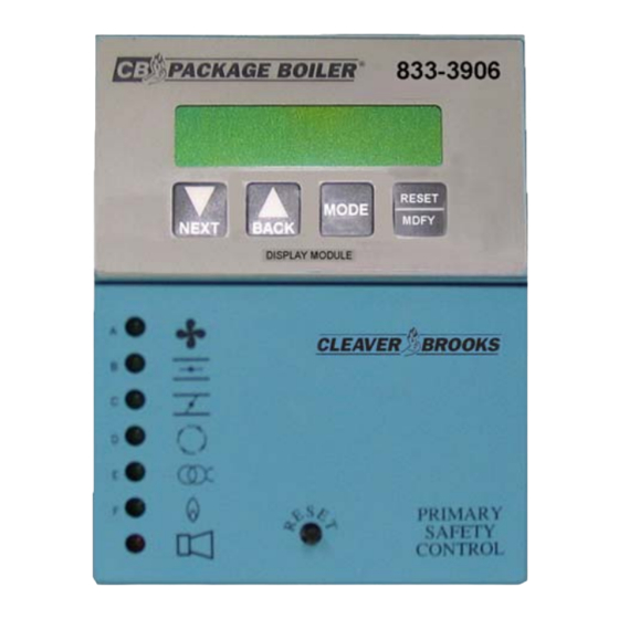
Mechanical Fittings: 1/2-14 NPT Pressure Sensors: Pressure Measurement Range: 0 to 15, 0 to 30, 0 to 200, 0 to 300 psig Excitation Voltage: 9-30Vdc (supplied by CB120Z control) Accuracy: +/- 0.25% Full Scale (at constant temperature) Output: 4-20 mA, linear with pressure... - Page 5 OPERATING TEMPERATURE LIMITS COMPONENT MAXIMUM MINIMUM Chassis/amplifier 140°F 60°C -40°F -40°C Programmers 140°F 60°C -40°F -40°C 833-3905 VFD Display 140°F 60°C -40°F -40°C 833-3906 LCD Display 140°F 60°C -4°F -20°C Scanner UV 200°F 93°C -40°F -40°C Scanner IR 140°F 60°C -40°F -40°C Flame Rod (Tip 2460°F)
- Page 6 ELECTRICAL RATINGS VA ratings (not specified as pilot duty) permit the connection of transformers and similar devices whose inrush current is approximately the same as their running current. VA Pilot Duty ratings permit the connection of relays, solenoid valves, lamps, etc. whose total oper- ating load does not exceed the published rating and whose total inrush current does not exceed 10 times the rating.
-
Page 7: Part Numbers And Approvals
PART NUMBERS AND APPROVALS Table 1: Agency Approvals CB120Z Chassis/Flame Amp. Module APPROVED 833-3726 (UV) 833-3727 (UVSC) 833-3728 (IR) CB120Z Programmer Module 833-3901 833-3902 833-3903 833-3904 CB120Z Displays 833-3905 833-3906 CB120Z Wiring Bases 833-3731 833-3730 X = CERTIFICATION IN HAND... -
Page 8: Ordering Information
833-3730 Open base with terminal block. 4"W x 7"H CB120Z Accessories 833-3156 Kit, remote mounting, CB120Z display, 4 ft. cable, provides NEMA 4 protection 833-3157 Kit, remote mounting, CB120Z display, 8 ft. cable, provides NEMA 4 protection 833-3539 Blank display module, included with chassis... - Page 9 SCANNER SELECTION CB P/N DESCRIPTION USE WITH CHASSIS 817-2261 Infrared 3’ 833-3728 832-1170 Replacement photo detector 817-2262 UV 3’ 833-3726 817-2263 UV 6’ 817-2124 Self-check UV 833-3727 817-4063 Replacement UV tube PRESSURE/TEMPERATURE SENSORS CB P/N DESCRIPTION 817-4480 Pressure sensor 0-15 psi 817-4481 Pressure sensor 0-30 psi 817-4482...
- Page 10 CHASSIS/AMPLIFIER 120 VAC, 50/60 Hz 833-3728 833-3729 833-3726 833-3727 FRONT VIEW SIDE VIEW (WITH OPTIONAL DISPLAY INSTALLED) (WITH OPTIONAL PROGRAMMER AND DISPLAY INSTALLED) DISPLAY MODULE PROGRAMMER MODULE 833-3901 833-3905 - VACUUM FLUORESCENT 833-3902 833-3906 - LIQUID CRYSTAL 833-3903 833-3904 WIRING BASE WIRING BASE 833-3730 833-3731...
-
Page 11: Installation Procedure
90% relative humidity continuous, non-condensing environment. Do not install the CB120Z system where it can be subjected to vibration in excess of 0.5G continuous maximum vibration. The CB120Z system is not a weather tight enclosure. The standard vertical position is recommended. - Page 12 FIGURE 2. WIRING BASE CONNECTIONS (shown for 120 VAC) Terminal No. Wire Color Type Description Rating 60-2852-1 60-2850-1 60-2854-1 L1 (Hot) Black Line voltage supply 120 VAC (+10%, -15%), 50/60 Hz L2 (Neu- White Line voltage common tral) EARTH Green Ground Red/Wht Scanner Input...
-
Page 13: Pressure And Temperature Sensor
The sensors must be located where the ambient temperature will not exceed the maximum ambi- ent operating temperature specified for the sensor. Insure that the pressure range programmed on the CB120Z Control matches the installed pres- sure sensor. Do not mount any of the sensors where they could be used as a footstep. - Page 14 Always mount the steam pressure sensor above the water line of the boiler. Locate the pressure sensors where the ambient temperature will not exceed 185F Use only a small amount of pipe compound to seal the connection joints. Excess pipe compound may clog the fitting and prevent proper operation of the sensor.
- Page 15 300V @105C. Use Belden 9318 or equivalent. The shield should be connected to the earth ground terminal on the wiring base of the CB120Z Control (Terminal #E). The shield should be taped at the sensor to avoid unintended contact with the sensor housing.
- Page 16 ‘pop’ the pro- grammer from the chassis. Note: The CB120Z system can only be used with 833-3901, 833-3902, 833-3903, or 833-3904 pro- grammers. All other programmer types will cause LOCKOUT, INVALID YP TYPE to be displayed.
-
Page 17: Cb120Z Programmer Selection
CAUTION: Restore power for the following test. With CB120Z installed, measure voltage from L2 to all other terminals. Reading should be zero on all terminals except Ll. INSTALL CB120Z INTO WIRING BASE The CB120Z chassis/amplifier module contains 2 screws permanently retained into the top and bot- tom of the housing. -
Page 18: Ptfi*Mtfi Timings
Non-recycle PTFI*MTFI TIMINGS The CB120Z system provides keypad selectable timings for both PTFI and MTFI. The selections offered can provide 5 or 10 second timing for terminal 5 and 6 or a shortened time for terminal 5, allowing for early spark termination. CB120Z also provides selectable interrupted or intermittent operation for terminal 6. -
Page 19: Led Indicator Lights
LED INDICATOR LIGHTS The CB120Z control module has seven (7) LED indicator lights to annunciate the operating status of the control, as well as provide the reason for the last lockout condition. The “Open Damper” and “Close Damper” LED's provide easy set-up of the modulating motor end switches. Each LED has a graphic symbol to describe its function (see Table 5 ). -
Page 20: Description Of Functions Of Operating Controls
8 hours of main burner (Terminal 7) on time. (This does not apply to Boiler Parms). The CB120Z display consists of 2 lines having 16 characters per line. The default displayed item is the current operating status. This would include the current point in the burner sequence followed by the parameter pertaining to that point in the sequence, such as time or the flame signal level. - Page 21 MODIFY Allows parameter to be modified/saved The CB120Z display system is made up of a number of circular menus and within these menus are sub-menus and in some cases further sub-menus within sub-menus. For example, within the BOILER PARMS sub-menu are additional sub-menus needed to set the various parameters for proper boiler operation, see Figure 7.
-
Page 22: Program Set Up Sub-Menu
PROGRAM SET UP SUB-MENU The sub-menu "PROGRAM SETUP" allows the user to review the various operational settings of the programmer module (e.g. programmer type, purge timing, etc.) and some instances modify the operational parameters to suit the application requirement. The MODE key is used to enter and exit the sub-menu and the NEXT and BACK keys are used to scroll through the menu as well as change the operational parameter. - Page 23 It is not necessary for the main burner on time to be continuous. The CB120Z accumulates burner on time in seconds. For example, assume power has been applied for 10 hours and the main burner has been on for 4 hours.
-
Page 24: Getting Started
It also serves as a permanent hard copy record. The CB120Z requires the user to program a number of operating parameters for proper system oper- ation. While the CB120Z Control offers a number of features and functions, a user can program four 750-271... -
Page 25: Set The Password
LEVEL 2 PASSWORD = 5 To enter the password of 02 for Level 1 and 05 for Level 2: From the CB120Z main menu (see Figure 4), use the NEXT or BACK keys to get to BOILER PARMS>. Press the MODE key to access the BOILER PARMS sub-menu. -
Page 26: Units Of Measure / Display Unit
MOD MAX settings. UNITS OF MEASURE / DISPLAY UNITS The CB120Z system provides the user with the option of working in ENGLISH or METRIC units. This parameter applies to both pressure and temperature units. With all boiler parameters set to UNUSED (out of the box condition), the item UNITS OF MEASURE will be available to select ENGLISH or METRIC. -
Page 27: System Test
LAG 1 and THERMAL SHOCK, are dependent on the selections made in this sub-menu. The STPT value is the target value the CB120Z will attempt to maintain. CUT IN is a differential value that is subtracted from the STPT and determines the point where a burner cycle begins. - Page 28 FIGURE 8. CONTROL VARIABLE CONFIGURATION SUB-MENU PRESS KEY FROM BOILER PARMS LOOP MODE MDFY TO CHANGE MDFY TO CHANGE MOD RNG 1.5P CUT OUT 2.0P MDFY TO CHANGE MDFY TO CHANGE MRGNL ALM 24.0P CUT IN 2.3P MDFY TO CHANGE LIMIT ALM 25.0P MDFY TO CHANGE...
-
Page 29: Sequence Of Operation - Operating Control
SEQUENCE OF OPERATION - OPERATING CONTROL Note: Refer to Figure 9. The CB120Z performs the operating control function to cycle the boiler on and off to maintain the programmed pressure or temperature setpoint. The CB120Z will command the burner on and off... -
Page 30: Sequence Of Operation - Modulating Control
SEQUENCE OF OPERATION - MODULATING CONTROL Note: Refer to Figure 10. The CB120Z also performs the modulating control function of the firing rate motor based on system demand. The position of the firing rate motor will operate according to the following setpoints:... - Page 31 While in STANDBY and with burner off, and from the ALL-INFO screen, pressing the MODE key will move to the top of the CB120Z Main menu where L1-3 OPEN or L1-3 CLOSED is dis- played. Pressing MODE again will move the display to either MOD USE if in AUTO mode or to MOD POS if in MAN mode.
-
Page 32: Sequence Of Operation - Marginal And High Alarm Limits
When complete, press the RESET/MDFY key to save the position. Pressing the MODE key will move the display to the top of the CB120Z Main menu screen and then to the ALL-INFO screen. The CB120Z system has bumpless transfer. If the burner is at the AUTO position and the current modulating mode is changed from AUTOMATIC (AUTO) to MANUAL (MAN) mode, MOD POS will assume the value of the current firing rate position. - Page 33 Once the steam pressure (or water temperature) increases by the calculated amount, the CB120Z increases the firing rate motor by the value of one segment and repeats the pro- cess. The CB120Z steps the firing rate motor until the steam pressure (or water temperature) reaches the Thermal Shock Exit Point (THML EXIT).
-
Page 34: Sequence Of Operation - Lead/Lag Control
SEQUENCE OF OPERATION - LEAD/LAG CONTROL In installations having multiple boilers, the CB120Z of each boiler can be set up to operate in a Lead/ Lag mode of operation. The CB120Z control provides two lead/lag setpoints, LAG1 and LAG2, each made active by separate 120 VAC digital inputs located on terminals 16 and 21. - Page 35 Lag Setpoint (LAG1 STPT). CUT OUT (Cut Out): This is the Cut Out value the CB120Z will use during Lag1 Operation. This is a differential value that is added to the Lag Setpoint LAG STPT). See SEQUENCE OF OPERA- TION - OPERATING CONTROL section.
-
Page 36: Alternate Uses For Lag2 Input
(100 PSI). Standby Water When a steam boiler is operating as the Lag Boiler in a Lead/Lag setup, the CB120Z can be pro- grammed to monitor the boiler water of the Lag steam boiler and bring the boiler on-line when the boiler water temperature falls below a programmed setpoint. -
Page 37: Sequence Of Operation - Standby Water
SEQUENCE OF OPERATION - STANDBY WATER When the CB120Z is controlling a steam boiler, the water temperature sensor connected to the AUX1 input can be pro- grammed to operate in a: Standby Lag Mode to monitor the boiler water of a steam boiler operating as the Lag boiler in a Lead/Lag setup and cycle the boiler “on”... -
Page 38: Standby Lag Mode
STANDBY LAG MODE To program the CB120Z to control a steam boiler in the “Standby Lag Mode”, the user programs the following setpoints which are found under AUX1 CONFIG>: STNDBY WTR: This selects the temperature sensor connected to the AUX1 input terminals will be used to monitor the boiler water of a steam boiler and programmed to operate in the STNDBY WTR mode. -
Page 39: Standby Thermal Shock Protection Mode
In Figure 14, whenever the boiler water temperature is above 190F (Cut out point), the Operating Control Output of the CB120Z is open. When the boiler water temperature falls to 180F (Cut in point), the Operating Control Output closes and a burner start-up sequence will be initiated. The CB120Z will modulate the firing rate damper motor based on boiler water temperature until the tem- perature rises above 190F (Cut out point). -
Page 40: Alternate Uses For Aux 1 Input
When the high limit alarm is exceeded, the CB120Z system will shutdown and lockout the boiler. The appropriate alarm message will be displayed. When AUX 1 is selected as Stack Temperature (STACK TEMP), the user has the option of sensor range, 32-350F or 32-752F. - Page 41 FIGURE 16. AUX 1 SUB MENU AUX 1 CONFIG > PRESS MODE TO ENTER UNUSED PRES 1030m 2060m 13.8B 20.7B NONE 200P 300P STNDBY 176C 400C NONE 350F 752F STNDBY STPT CUT IN CUT OUT MOD RNG MNITR TEMP 176C 400C NONE 350F...
-
Page 42: Alternate Uses For Aux 2 Input
(OUTDR STPT) can then be programmed so that when the outdoor air temperature is above this inhibit setpoint, the operating control circuit of the CB120Z system will not respond to system demand and initiate a burner cycle. While this condition exists the display will indicate OUTDR TEMP>... - Page 43 FIGURE 17. AUX 2 SUB MENU AUX 2 CONFIG > PRESS MODE TO ENTER UNUSED PRES 1030m 2060m 13.8B 20.7B NONE 200P 300P MNITR TEMP 176C 400C NONE 350F 752F OUTDR TEMP 176C 400C NONE 350F 752F OUTDR STPT STACK TEMP 176C 400C...
-
Page 44: Flame Scanners
FLAME SCANNERS CAUTION: The UV1A, UV2, UV8A, UV90 and 45UV3 flame scanners and associated amplifier module are non-self checking UV systems and should be applied only to burners that cycle often (e.g.: a minimum of once per 12 hours) in order for the safety checking cir- cuit to be exercised. -
Page 45: Operation - 45Uv5 & 55Uv5 Self-Checking Uv Scanner
If the shutter assembly in the scanner fails, the tube is faulty, or there is insufficient power to the scanner, the CB120Z will LOCKOUT and display the following message LOCKOUT CHECK SCANNER. The ultraviolet tube is replaceable (P/N 4-314-1). -
Page 46: Wiring - Uv Scanners
FIGURE 19. SHUTTER OPEN 3.7 SEC. SHUTTER CLOSED 0.4 SEC. TIME WIRING - UV SCANNERS To connect the scanner to the control, the UV1A Scanner is supplied with 36" or 72" of flexible cable. The 45UV5 is supplied with four 72" lead wires. Install them in a suitable length of flexible armor cable and connect it to the control. -
Page 47: Operation - Ir Learn
LEARN process. ‘Out of the box’, the CB120Z IR system is shipped with its sensitivity and thresholds set to detect most firing conditions. The purpose of the LEARN process is to trim the sensitivity, either upward or downward, to the level required for reliable flame detection and most importantly for an overall improvement in detecting a flame out against various background conditions. - Page 48 In oil fired units this may be caused by a sudden interruption in the oil delivery. The CB120Z utilizes this information to make a decision to keep the burner on line or force a shut down. If the background radiation (brightness) changes downward by 20% in a 25 msec period and stays at this level for 1 FFRT, the decision to shut down will be made.
-
Page 49: Installation - 69Nd1 Flame Rod
INSTALLATION - 69ND1 FLAME ROD The 69NDl flame rod proves a gas pilot flame and/or main gas flame. It is a spark plug type unit con- sisting of 1/2' “NPT” mount, a KANTHAL flame rod, a glazed porcelain insulating rod holder and a spark plug connector for making electrical connections. -
Page 50: System Operation
MODE SYSTEM OPERATION The programmer module determines the functional operation of the CB120Z control (e.g. purge tim- ing, trial for ignition timings, recycle or non-recycle operation, etc.). For purposes of illustration, we will be looking at the 833-3901 Programmer functions and messages associated with the 833-3906 display module in this bulletin. -
Page 51: Operating Sequence
Operating Sequence Terminal PTFI MTFI AUTO Post STANDBY Purge Operating control and pcv < cut in Cycle complete Air flow (terminal P) must close within 10 seconds of HFS (M-8) closing Valve closes in one second 13 (POC) Proof of valve closure Don't care state PTFI/MTFI times keypad select- able... - Page 52 Refer to PTFI*MTFI TIMINGS to determine times selected or timings appropriate for the application. The test meter jacks on the CB120Z will provide an indication of the flame signal strength. The flame signal readout is also available on the alpha-numeric display.
-
Page 53: Normal Shutdown
Normal Shutdown When the operating control circuit (L1-3) opens, the main fuel valve is de-energized. The firing rate motor is driven to the low purge position (10-12 circuit made). Following a 15 second post purge, the burner/blower motor is de-energized. POST PURGE 0:05 CYCLE COMPLETE... -
Page 54: Suggested Wiring Diagram For Yp138 Programmer
SUGGESTED WIRING DIAGRAM FOR 833-3147 PROGRAMMER FIGURE 22. 750-271... -
Page 55: Lockout Codes
CB120Z will wait up to 20 seconds for the 3-P circuit to close. 2. At cycle start (L1-3 closes), if the M-8 damper switch is open, the CB120Z will wait up to 10 seconds for the 3-P circuit to close after the M-8 circuit closes. Pre-purge timing begins after the M-8 closes circuit closes. -
Page 56: Diagnostic Messages
RESETTING THE CONTROL The CB120Z systems contain three methods of reset, by push-button located on the chassis/amplifier module, by keypad push-button located on the optional keypad/display module, and by normally open push-button connected to LAG2 input (terminal 21). LAG2 is a line voltage isolated input. -
Page 57: Lockout Codes
LOCKOUT CODES During an alarm condition, the Alarm LED is made to flash at approximately a twice per second rate. The remaining LED’s are illuminated as a coded sequence identifying the reason for the lockout. This remains true if power is removed and then restored in a locked out condition. Table 6: LED DISPLAY READOUT = ON... -
Page 58: Lockout History Sub-Menu
LED DISPLAY READOUT = ON CHECK EXPANSION MODULE LOCKOUT MESSAGE OPEN CLOSE AUTO FLAME DAMPER DAMPER PCV UNDER RNG PCV OVER RNG PCV HIGH LIMIT AUX1 UNDER RNG AUX1 OVER RNG AUX2 UNDER RNG AUX2 OVER RNG AUX1 HIGH LIMIT AUX2 HIGH LIMIT LOCKOUT HISTORY SUB-MENU The sub-menu "LOCKOUT HISTORY"... - Page 59 FIGURE 23. KEY FROM MAIN MENU LOOP PRESS MODE LO #9 PURGE LO #9 PURGE @ BNR HOUR @ BNR CYCLE LO #9 PURGE 3-P INTLK OPEN LO #1 PTFI LO #10 STANDBY FLAME FAIL @ BNR CYCLE LO #10 STANDBY @ BNR HOUR LO #1...
-
Page 60: Communications
COMMUNICATIONS The protocol to be used is Modbus RTU. This is implemented by the master (PC, PLC, etc.) issuing a poll to the slave (CB120Z) and the slave responding with the appropriate message. MESSAGE FORMAT DST refers to the logical address of the slave. -
Page 61: Modbus Message Table
MODBUS MESSAGE TABLE Table 7: HOLDING MESSAGE WORD WORD VALUE REGISTER ADDRESS REQUESTED RESPONSE 40001 STATUS 83 (053H) = RUN; 202 (0CAH) = LOCKOUT 40002 MSGN Current message being displayed (see Table 10) 40003 GSTAT Defines Timer Type 40004 TIMER Time in seconds 40005 FLAME... -
Page 62: Boiler Operating Parameters
HOLDING MESSAGE WORD WORD VALUE REGISTER ADDRESS REQUESTED RESPONSE BOILER OPERATING PARAMETERS 40100 Calibration Constant (used to normalize A/D readings) 40101 Primary sensor Raw A/D reading 40102 AUX 1 sensor Raw A/D reading READ Only Values 40103 AUX 2 sensor Raw A/D reading 40104 LEAD / LAG status 40105... - Page 63 HOLDING MESSAGE WORD WORD VALUE REGISTER ADDRESS REQUESTED RESPONSE 40150 LAG 2 Lag Mode 40151 LAG 2 Start Delay 40152 LAG 2 Lead to Lag Delay 40153 LAG 2 Sensor Set Point 40154 LAG 2 Sensor Cut In 40155 LAG 2 Sensor Cut Out 40156 LAG 2 Sensor Mode Range Except as noted, all boiler...
-
Page 64: Inputs
0 then the TIMER value has no meaning. The value in TIMER is a background minute timer in the CB120Z and should be ignored. If GSTAT is between 4 and 7, the TIMER represents the cur- rent value flame signal. If GSTAT is a 1, 2, or 3 then TIMER represents a running timer value. -
Page 65: Outputs
OUTPUTS (40008) Bit 15 Bit 11 Bit 8 Term A Term 11 Term X Term 12 Alarm Bit 7 Bit 3 Bit 0 Term W Term 7 Term M Term 6 Term 5 Internal Delayed Main Blower Pilot Ignition Safety Valve Valve Valve... -
Page 66: Explanation Of Logstat
On 833-3903 programmer, when terminal 21 first energized, wait for M-D to close AUTO Post Purge POSTPURGE Post Purge period if flame fail lockout POSTPURGE Idle state if unit is in lockout POSTPURGE PRE PURGE Logstat represents the current software module the CB120Z is currently executing. 750-271... - Page 67 The CB120Z outputs the current displayed message as well as the historical lockout messages as numbers. The table below correlates the message number with the actual displayed text message. Table 10: STATE CB120Z MESSAGES M-D LOW LIMIT OPEN - AUTO...
- Page 68 STATE CB120Z MESSAGES SYSTEM DIAGNOSTIC MESSAGES LOCKOUT CHECK CHASSIS LOCKOUT CHECK PROGRAMMER See Interlock Annunciation Message Table LOCKOUT CHECK EXPANSION MODULE LOCKOUT CHECK WIRING LOCKOUT CHECK FUSE LOCKOUT CHECK SCANNER LEARNING FLAME (PTFI and AUTO) PURGE INTERLOCK RELATED MESSAGES HOLD M-8 LIMIT CLOSED...
- Page 69 STATE TERMIN YZ300 INTERLOCK ANNUNCIATOR LOCKOUT MESSAGES HIGH WATER 3-43 LOW WATER 43-44 HIGH GAS PRESSURE 51-52 LOW GAS PRESSURE 50-51 AUX GAS 52-54 LOW OIL PRESSURE 47-48 HIGH OIL TEMPERATURE 44-46 LOW OIL TEMPERATURE 46-47 LOW ATOMIZING MEDIA 48-50 HIGH PRESSURE 54-55 HIGH TEMPERATURE...
-
Page 70: Operational Features
OPERATIONAL FEATURES 4-20 mA TEST JACKS For all amplifier types, the CB120Z provides 4-20 mA test jacks to represent the flame signal strength. The test jacks are located RUN/CHK RUN/CHK on the underside of the chassis module (pictured at right). The ‘+’... -
Page 71: Check-Run Switch
CHECK-RUN SWITCH The Check-Run switch is located on the underside of the chassis module (note drawing on right) and can be used to stop the con- RUN/CHK RUN/CHK trol in its firing sequence at any time in the burner sequence. It is COMMS COMMS designed to aid in set-up, start-up and check-out of the burner and... -
Page 72: Operational Test
OPERATIONAL TEST WARNING: Before testing the control operation on the boiler, close the manual main shut- off fuel valve. Failure to do this may cause injury or property damage. Close the manual main shut-off fuel valve. Recheck all limit circuit wiring for proper operation and correct connection. Confirm that the automatic main fuel valves are wired to terminal “7.”... - Page 73 read no signal more than 4. If more than 4 is observed, realign the UV scanner, and/or shield the spark from the scanner’s view. With all methods of flame detection, check pilot flame failure response by manually shutting off the pilot fuel and then initiate a normal start-up. With no pilot flame present, the control will de- energize the pilot assembly at the end of the trial for ignition interval, and the control will lock- out.
-
Page 74: Suggested Grounding Rules
(not intermediate sub-panels) to the burner control panel and insure that this ground wire is well bonded to the control panel. The wiring base of the CB120Z must have earth ground providing a connection between the sub-base and the control panel or the burner. - Page 75 Remote Display To locate the display remotely from the CB120Z control, mounting kits are available. These are Fir- eye part numbers 129-178-4 or 129-178-8. Each kit contains a gasket, hardware to mount the display and a 4 or 8 foot cable.
- Page 76 Routine observation of the flame signal strength will forewarn any deterioration in the capability of the flame detector or its application. Contacts There are no accessible contacts in the CB120Z. Where contacts are used, their design assures long trouble-free life when the load circuits are maintained within the published load ratings. Humidity In areas of high humidity, the control chassis should be removed and placed in a dry atmosphere when the system is expected to be out of service for an extended period.
-
Page 77: Cb120Z Programming / Setup Guide
CB120Z PROGRAMMING / SETUP GUIDE JOB: DATE: SETPOINT UNUSED SETTING NOTES MOD USE AUTO MOD POS 0-100% MOD MAX 0-100% PCV INPUT STEAM WATER PCV PRES 0-15P 0-30P 0-200P 0-300P STM STPT CUT IN CUT OUT MOD RNG MRGNL ALM... - Page 78 SETPOINT UNUSED SETTING NOTES LAG1 MODE LAG1 STPT CUT IN CUT OUT MOD RNG STRT DLY 0 to 15 min LAG DLY 0 to 15 min MOD MAX LAG2 MODE RESET P-HOLD I-HOLD PROCESS FRCD ON LAG2 STPT CUT IN CUT OUT MOD RNG STRT DLY...
- Page 79 NOTES 750-271...
Need help?
Do you have a question about the CB120Z and is the answer not in the manual?
Questions and answers