
Subscribe to Our Youtube Channel
Related Manuals for Rockford Fosgate Prime R1-HD2-9813


Summary of Contents for Rockford Fosgate Prime R1-HD2-9813
- Page 1 All manuals and user guides at all-guides.com HARLEY-DAVIDSON ® 2-SPEAKER KIT R1-HD2-9813 Serial Number: Date of Purchase:...
- Page 2 Road Glide Ultra 14-15 Installation All Models 16 Warranty ©2014 Rockford Corporation. All Rights Reserved. ROCKFORD FOSGATE and associated logos where applicable are registered trademarks of Rockford Corporation in the United States and/or other countries. Ultra Classic ® , Electra Glide ®...
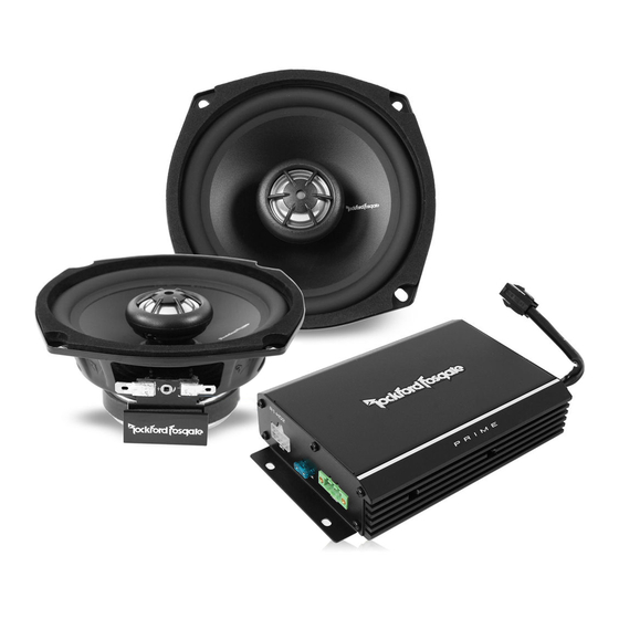
- Page 3 All manuals and user guides at all-guides.com Model R1-HD2-9813 Description 2-Channel Watts Per Channel (RMS) 70W X 2 Crossover Frequency Fixed 5.24in (133.0mm) Frequency Response 95Hz-20kHz Level Control -3dB, 0dB, +3dB Fuse Rating Nominal Diameter 5.25” (133 mm) 3.87in (98.3mm) Description 2-Way Nominal Impedance...
- Page 4 All manuals and user guides at all-guides.com Amplifier Mounting Bracket ® The bracket is to be used on Road Glide and Road Glide Ultra ® motorcycle fairings only. It mounts to the brake side turn signal bracket. 2-Channel Amplifier 2-channel amplifier. Level Control Power Harness Connector Recommended level should be set to -3dB.
- Page 5 No adapter is needed. Standard Spade Connector The spade terminals accept both 1/8” (negative) and 1/4” (positive) connectors from the new Speaker Output Harness. Grille Badge Adhesive backed Rockford Fosgate badges attach to the factory speaker grill. (Ultra Classic ® , Electra Glide ®...
- Page 6 All manuals and user guides at all-guides.com FRONT Speaker Output Harness Black Green 4-Pin 3-Pin Black Clutch Side Brake Side 4-Pin Front Speaker Input - Clutch (Connect to factory speaker wire) Front Speaker Input - Brake (Connect to factory speaker wire) NOTE: Due to the limited space available, be sure to connect all of the wiring harnesses to the amplifier prior to mounting.
- Page 7 All manuals and user guides at all-guides.com Contents Installation Considerations 2-Channel Amplifier Mounting Screws This section focuses on some considerations for installing your motorcycle audio kit. This manual will illustrate the installation of two different fairing Amplifier Mounting Bracket Zip Ties styles offered by Harley-Davidson ®...
- Page 8 All manuals and user guides at all-guides.com Ultra Classic ® , Electra Glide ® , Street Glide ® ® Tri Glide models. You will need to disconnect the harness from the headlight to completely take the fairing off of the motorcycle. Step 2 - Speaker Removal Step 1 - Fairing Removal After the fairing is removed, unplug the wires from both speaker...
- Page 9 All manuals and user guides at all-guides.com Step 5 - Amplifier Mounting NOTE: You can insert the one side of the speaker into the assembly and use a flat bladed screwdriver or pry bar to gently pry the grille Without Communication Module onto the speaker for a tight fit.
- Page 10 All manuals and user guides at all-guides.com Step 6 - Fairing Speaker Wiring Take the factory speaker wires and plug them directly in to the new High-Level Input Harness. These are labeled clutch and brake side. Now you can plug the new Speaker Output Harness onto the Rockford speaker terminals.
- Page 11 All manuals and user guides at all-guides.com ® ® Pull the fairing toward the front of the bike and up to release it from Road Glide and Road Glide Ultra models. the fairing mounts. Unplug headlight harness and set fairing aside. Step 1 - Removal Leaving the windshield in place, remove the six inner fairing Step 2 - Speaker Removal...
- Page 12 All manuals and user guides at all-guides.com Step 3 - Speaker Install Step 5 - Amplifier Mounting Reattach the new Rockford speaker to the backside of the factory Attach the amplifier to the bracket using the supplied hardware. grille assembly. Be sure to orientate the speaker with the terminals Mount the bracket to the brake side turn signal bracket.
- Page 13 All manuals and user guides at all-guides.com Step 6 - Fairing Speaker Wiring Take the factory speaker wires and plug them directly in to the new High-Level Input Harness. These are labeled clutch and brake side. Now you can plug the new Speaker Output Harness onto the Rockford speaker terminals.
- Page 14 All manuals and user guides at all-guides.com All Models The gas cap should not be left off. Once the console is off put the cap back on to Step 8 - Routing Power Harness prevent any gas fumes creating a potential Pass the power harness through the fairing and route next to the fire hazard.
- Page 15 All manuals and user guides at all-guides.com ® ® Badge Installation - Ultra Classic , Electra Glide , Street Glide ® and Tri Glide ® models. Peel the backing off of the badge. Place it on top of the speaker grille and press firmly.
- Page 16 All manuals and user guides at all-guides.com All Models The gas cap should not be left off. Once the console is off put the cap back on to Step 8 - Routing Power Harness prevent any gas fumes creating a potential Pass the power harness through the fairing and route next to the fire hazard.
- Page 17 What is Covered This warranty applies only to Rockford Fosgate products sold to consumers by Authorized Rockford Fosgate Dealers in the United States of America or its possessions. Product purchased by consumers from an Authorized Rockford Fosgate Dealer in another country are covered only by that country’s Distribu- tor and not by Rockford Corporation.
- Page 18 All manuals and user guides at all-guides.com Installation assistance availible at: www.rockfordfosgate.com/rftech R O C K F O R D F O S G A T E . C O M...
Need help?
Do you have a question about the Prime R1-HD2-9813 and is the answer not in the manual?
Questions and answers