Table of Contents
Advertisement
Quick Links
Advertisement
Table of Contents

Summary of Contents for JST MP-CB (CE)
- Page 1 MP-CB (CE) Operation manual...
-
Page 2: Table Of Contents
MP-CB (CE) Contents Page 1. Preface 2. Specification 3. Control box connection to MP termination press 4. Control box connection to MP cover press 5. Control box connection to YA tool 6. Air pressure adjustment 7. Timer control adjustment 8. Counter 9. -
Page 3: Preface
MP-CB (CE) Preface The MP-CB (CE) pneumatic control box when combined with the applicable presses gives a consistent terminating operation. The suitable presses for use with the MP-CB (CE) are: MP-2AW-RSD/RST MP-2A-RSDC/RSTC MP-2LW-RSTD MP-2AW-RSV MP-2AW-RSX MP-2A-RSVC MP-2LW-RSX YA-1A YA-4A Before using the MP-CB (CE) please read this manual to ensure that you are familiar with its operating controls. -
Page 4: Specification
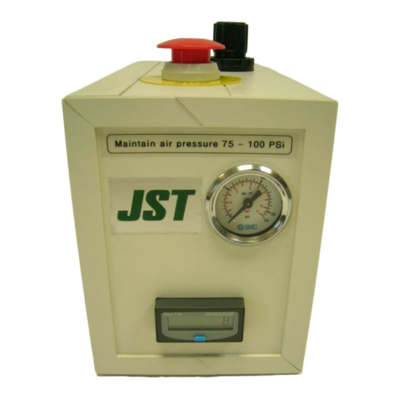
MP-CB (CE) 2. Specifications Model: MP-CB (CE) Dimensions (mm): 200(H) x 130(W) x 320 (D) Weight: 4kg Air supply: 75 – 100 Psi Page 3 of 15... -
Page 5: Control Box Connection To Mp Termination Press
MP-CB (CE) 3. Connecting the control box to the MP termination press 1. Footswitch – Connect pipe No.1 from the control box to port marked No.1 on the footswitch. Connect pipe No.2 from the control box to the main air to the footswitch connection Main supply Port marked No.1 2. - Page 6 MP-CB (CE) 3. Connecting the control box to the MP termination press 3. MP press connection – Connect pipe No.1 from the control box to the No.1 connection on the MP press cylinder. Connect pipe No.2 from the control box to the lower connection on the press.
-
Page 7: Control Box Connection To Mp Cover Press
MP-CB (CE) 4. Connecting the control box to a MP cover fitment press 1. Footswitch – Connect pipe No.1 from the control box to port marked No.1 on the footswitch. Connect pipe No.2 from the control box to the main air to the footswitch connection. Main supply Port marked No.1 2. - Page 8 MP-CB (CE) 4. Connecting the control box to a MP cover fitment press 3. MP press connection – Connect pipe No.1 from the control box to the No.1 connection on the MP press cylinder. Connect pipe No.2 from the control box to the lower connection on the press.
-
Page 9: Control Box Connection To Ya Tool
MP-CB (CE) 5. Connecting the control box to a YA tool 1. Fit the foot pedal connections as shown: Stem plug 8mm Stem reducer 4mm-8mm Reducer elbow 4mm – 8mm 2. Connect the red port on the foot pedal to number 1 footswitch connection on the MP-CB(CE) control box. -
Page 10: Air Pressure Adjustment
MP-CB (CE) 6. Air pressure adjustment 1. Move the air pressure control knob upwards, this will allow any adjustment that is required. Turn the knob to achieve the recommended air pressure, push it back downwards to lock the adjustment. Air pressure = 75 – 100 Psi Page 9 of 15... -
Page 11: Timer Control Adjustment
MP-CB (CE) 7. Timer delay adjustment 1. Slide the upper vent cover upwards and off. 2. On top of the control box is a small hole, in this hole is the screw to adjust the timer delay. 3. Turn the screw to adjust the timer delay. Turning the screw clockwise will increase the timer delay. -
Page 12: Counter
MP-CB (CE) 8. Counter To reset the counter to zero press the blue button. Page 11 of 15... -
Page 13: Trouble Shooting
MP-CB (CE) 9. Trouble shooting Problem Check Pipes No. 3 and 4 are Air blows when the carriage or connected into the correct connector plate is not pushed to carriage sensor positions on the terminating position. both the control box and the press. -
Page 14: Pneumatic Circuit Diagrams
MP-CB (CE) 10. Pneumatic circuit diagrams MP-CB (CE) used with MP termination press: Page 13 of 15... - Page 15 MP-CB (CE) 8. Pneumatic circuit diagrams MP-CB (CE) used with a MP cover fitment press or a YA tool. Page 14 of 15...
-
Page 16: Parts List
MP-CB (CE) 9. Parts list Parts List For MP-CB (CE) Press Control Unit Item Description Part Number Quantity Control box location Gauge 10bar 40mm panel mount 4K8-10P Front panel Male connector 6mm – 1/8 KQH06-U01 Valve / dump valve connections Bulkhead union 4mm tube KQE04-00 Rear panel connections...
Need help?
Do you have a question about the MP-CB (CE) and is the answer not in the manual?
Questions and answers