Table of Contents
Advertisement
Quick Links
Advertisement
Table of Contents

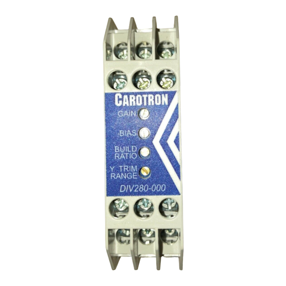
Summary of Contents for Carotron DIV280-000
- Page 1 Divider Module Instruction Manual DIV280-000...
-
Page 2: Table Of Contents
6. Prints ........................... 14 C13814 DIV280-000 Block Diagram..............14 C13813 DIV280-000 Assembly ................15 C13815 DIV280-000 General Connections ............16 7. Standard Terms & Conditions of Sale ................. 17 List of Figures Figure 1: Winder Speed vs Winder Diameter (10:1 Build Ratio) ........3 Figure 2: Physical Dimensions .................. -
Page 3: General Description
Speed). The tension applied to the material on a takeup or letoff would be held constant during roll diameter changes. Model DIV280-000 is designed for the above industrial applications where the division of DC voltage signals is required to produce the non-linear plot. The module has two voltage inputs (X &... -
Page 4: Specifications
2 2 2 2 Specifications 2.1 Electrical D.C. Power Input Signal Output 24 VDC ±10%, 60mA max, Voltage Output • • internally fused Selected by position V on J2. This circuit allows the output to source a +10VDC Reference Output voltage level of up to +10 VDC into a 10mA max •... -
Page 5: Installation
Any relay, contactor, starter, solenoid or other electro-mechanical device located in close proximity to or on the same line supply as the DIV280-000 should have a transient suppression device such as an MOV or R-C snubber connected in parallel with its coil. -
Page 6: Description Of Features & Adjustments
4 4 4 4 Description of Features & Adjustments JUMPER J2 Selects the Output Mode between Voltage or Current. Position V on J2 selects the Voltage Mode and the output is sourced from terminals 7 & 8. Position I on J2 selects the Current Mode and the output is sourced on terminals 7 &... -
Page 7: Adjustment Procedure
Teach input from circuit common. If an error is made during the teach process, simply repeat the procedure. 5 5 5 5 Adjustment Procedure WARNING! DURING CALIBRATION, THE DIV280-000 MODULE WILL PRODUCE AN OUTPUT. PLEASE DISCONNECT ANY EQUIPMENT FROM THE MODULE THAT COULD BE DAMAGED OR CAUSE INJURY DURING THIS PROCESS. -
Page 8: Velocity Mode Winder
5.1 Velocity Mode Winder The DIV280-000 can be used as a velocity mode winder control. In this application, the winder controls/sets the material speed. As the diameter increases, the center driven winder speed must be reduced in order to maintain a constant material speed. The DIV280-000 module calculates the winder speed signal by dividing the line speed by diameter. - Page 9 Step 1: Select Output Type 1. Select the type of output desired using Jumper J2. If a Voltage output is desired, select V on J2 and use output terminals 7 (OUTPUT) and 8 (VOLTAGE RETURN). If a Current output is desired, select I on J2 and use output terminals 7 (OUTPUT) and 9 (CURRENT RETURN).
- Page 10 Step 8: Final Settings 1. The external Line Speed potentiometer can be used to set the desired material speed. As the diameter builds, the DIV280-000 will decrease the velocity signal to the winder to maintain a constant material speed.
-
Page 11: Torque Mode Takeup/Letoff
5.2 Torque mode Takeup/Letoff Another common application for the DIV280-000 module is the basic torque mode takeup (winder) or letoff (unwinder). The module takes a line speed signal and divides it by a roll speed signal to calculate a diameter (or torque) signal. The diameter signal can then be trimmed by an external Tension potentiometer to provide a torque reference for a motor or a brake. - Page 12 Once calibration is completed, the potentiometer is dis-connected and the actual roll speed signal is re-connected. If needed, please contact Carotron for assistance in performing this calculation. Rotate the potentiometer to minimum. Connect the Teach Y input (terminal 12) to circuit...
- Page 13 2. If a minimum torque level is desired when stopped, a torque bias level must be set in the drive or the brake controller. The DIV280-000 will then add to this level once motion starts and the diameter/torque level calculation begins.
-
Page 14: Prints
6 6 6 6 Prints... -
Page 17: Standard Terms & Conditions Of Sale
1. General charges any such system to so perform, which system is found to the The Standard Terms and Conditions of Sale of Carotron, Inc. (hereinafter Company’s satisfaction to have failed to so perform, or refund to the called “Company”) are set forth as follows in order to give the Company Purchaser the purchase price paid by the Purchaser to the Company in and the Purchaser a clear understanding thereof. - Page 18 3204 Rocky River Road Heath Springs, SC 29058 Phone: 803.286.8614 Fax: 803.286.6063 Email: saleserv@carotron.com Web: www.carotron.com MAN1060-00 Rev. B Issued 10-11-2018...

Need help?
Do you have a question about the DIV280-000 and is the answer not in the manual?
Questions and answers