Table of Contents
Advertisement
Quick Links
Advertisement
Table of Contents

Related Manuals for Shihlin electric BW-2000

Summary of Contents for Shihlin electric BW-2000
- Page 1 http://www.seec.com.tw http://circuit-breaker.seec.com.tw...
-
Page 3: Table Of Contents
Contents Speci cation 1. Introduction 1.1 Purposes 1.2 Type designation 1.3 Classi cation 1.4 Conditions of Use 2. Structure speci cations 3. Intelligent controller 3.1 Function comparison table 3.2 Protection Parameter 3.2.1 Overload Long time delay protection characteristics 3.2.2 Short-circuit short time delay protection characteristics 3.2.3 Short-circuit instantaneous protection characteristics 3.2.4. -
Page 4: Speci Cation
Model BW-2000 BW-3200 BW-4000 BW-6300 Frame size 2,000 3200 4000 6300 630/800/1000/ Rated current (In) 2000/2500/3200 3200/4000 5000 6300 1250/1600/2000 AC400, 690V AC400, 690V AC400, 690V AC400, 690V Rated operation voltage(Ue) 50/60Hz 50/60Hz 50/60Hz 50/60Hz Rated insulation AC1000 AC1000 AC1000... -
Page 5: Introduction
1. Introduction 1.1 Purposes The rated voltages of BW series air circuit breakers (referred to as circuit breakers) are rated voltage AC400V, 690V, 50/60HZ. The rated current is from 630 to 6300A. It's used for distributing power and protecting circuits in the electrical distribution system is protected from overloading, voltage shortage, short circuit, earthling, and other hazardous faults. -
Page 6: Structure Speci Cations
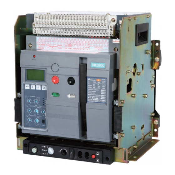
2. Structure Speci cations 1. Secondary circuit terminal (Fixed) 2. Cradle 3. Shutter 4. Handle 5. Secondary circuit terminal (movable) 6. Auxiliary contacts 7. Shunt release 8. Closing coil 9. Operation mechanism 10. Intelligent controller 11. Panel 12. Motor driven ACB-OB... -
Page 7: Intelligent Controller
3. Intelligent Controller 1. Reset button 2. LCD display 3. LED status indicator 4. Function buttons 5. Rotary protection setting Setting Earthing Instantaneous tripping Earthing delay ACB-OB... -
Page 8: Function Comparison Table
3.1 Function Comparison Table Controller XSIC-A XSIC-P Overload long-delay protection Short-circuit, short-delay protection Protection Instantaneous protection function Earthing/leakage protection/None (Optional) Phase failure protection Current measurement Imbalance current ratio measurement Fault record functions Thermal memory functions Contact point wearing and machine lifespan indication Other programming port functions... -
Page 9: Short-Circuit Short Time Delay Protection Characteristics
3.2.2 Short-circuit Short time delay Protection Characteristics Intelligent controller's short-circuit Short time delay protection methods comprises inverse time protection and de nite time restriction protection. 1. Inverse time protection: When the fault current exceeds the present setting current value but is smaller than (10I the maximum setting short-circuit current (10Ir), the controller will carry out protection according to the inverse time curve. -
Page 10: Unsymmetrical Earthing / Leakage Protection Characteristics
3.2.4 Unsymmetrical Earthing / Leakage Protection Characteristics Intelligent controller's earthing protection methods comprise inverse time protection and definite time protection. 1. Inverse time protection: When the fault current exceeds the present setting current but is smaller than 5Ig, the controller will carry out protection based on the inverse time curve. -
Page 11: Load Monitoring Protection Characteristics
Intelligent Another is transformer mode of external leakage. The controller gets the output current signal from a current transformer controller Intelligent Intelligent controller directly to protect. Generally, the secondary output of the transformer is 5A/1A (secondary current is 1A if primary current controller of transformer is less than 400A, else is 5A). -
Page 12: Phase Failure Protection Characteristics
The controller can program the output of two passive signal contacts for load monitoring. The output signal contacts can be used for monitoring alerts, controlling the load of tripping sub-circuit and ensuring a normal power supply for the main system. There are two types of load monitoring methods available (the user can choose one of them). - Page 13 Self-diagnosed functions When the working environment of the controller exceeds 65 C or when 60% of the contact has been worn o , or when the circuit breaker cannot be tripped, the light "TAL" on the controller panel will be on to alert the user. Relevant parameters will be recorded for later inquiry.
- Page 14 Table 8. Factory Default Setup for the Four Contact Sets of the Controller Contact code Contact 1 Contact 2 Contact 3 Contact 4 Controller types Short-circuit Short-circuit, XSIC-A Overload Self-diagnosis instantaneous short-delay XSIC-P Overload Self-diagnosis Note: 1. When the overload monitoring function is turned on, the functions of contact 3 and 4 are xed to "Load 1 Unloading Output"...
-
Page 15: Characteristics Curves
4. Characteristic Curves 4.1 Overload, Short-circuit, Instantaneous Protection 10000 5000 =0.4…1×In 2000 1000 =5~250s =1.5~10×I 0.4s t ON 0.4s 0.3s 0.3s 0.2s 0.2s t OFF 0.1s 0.1s 0.05 =2~15I 0.02 0.01 4.2 Earthing Protection 30min 20min 14min 10min 6min 4min 2min 1min Earthing Protection... -
Page 16: Leakage Protection
4.3 Leakage Protection 30min 20min 14min 10min 6min 4min 2min 1min 0.5A 1.0s 0.8s 0.6s 0.5s 0.4s 0.3s 0.2s 0.2s 0.1s 0.1s 0.06s 0.05s 0.02s 0.01s 500 1000 20 30 ACB-OB... -
Page 17: Accessories
5. Accessories and functions 5.1 Shunt release, Undervoltage release, Motor-driven, Closing coil Rated voltage Required power Items 220V 380V 110V 220V Shunt release 24VA 36VA ─ Under voltage release 24VA 36VA ─ Motor-driven mechanism 85VA/ 110VA/ 150W 85VA/ 110VA/ 150W 85W/ 110W/ 150W 85VA/ 110W Closing coil... -
Page 18: Lock Devices
5.3 Lock devices (optional) 5.3.1 Mechanical interlock (ATS use) The interlock device is installed on the right side of ACB. The maximum of 3 units of ACB can be installed vertically, and 2 units horizontally. It prevents the 2 or 3 ACBs close at the same time. breaker 1 breaker 2 basic point... - Page 19 ACB mechanical interlock action gure wiring possible cause wiring possible cause 2×breaker lock 3×breaker lock 2×normal power + 1×back up power wiring possible cause 3×breaker lock 3×normal power for one breaker wiring possible cause 3×breaker lock double power and one switch 5.3.2 Three-lock-two-key interlocking device (Fig.
-
Page 20: Testing Kit
5.4 Testing Kit This testing device (ACB Tester) is an optional accessory, speci c for ACB XSIC-II Intelligent controller. ACB tester is mainly used to test ACB at site for routine check or repairing. 6. Wiring 6.1 Controller and Circuit Breaker Wiring External power RS485 communication port Voltage display... -
Page 21: Secondary Wire Diagram
6.2 Secondary Wiring Diagram 6.2.1 XSIC-A Series Intelligent Controller To the circuit breaker input wire External transformer Power storage Tripping Closing Power Electric Main storage motor Auxiliary contact Intelligent controlle indica- operation computer device 6.2.2 XSIC-P Series Intelligent Controller To the circuit breaker input wire RS485... -
Page 22: Ats Wiring Diagram
6.2.3 ATS Wiring Diagram Attention: 1. TR1、TR2: Timer relays are additional device, delay time ≥ 5s. (Not included) 2. Input control voltage is AC220V, please use transformer to step up or step down the voltage(Transformer capacity is 300VA or above) 3. -
Page 23: Outline And Installation Dimensions
2000A Compartmentdoor position 421(connection position) 467(disconnection position) 123.5 123.5 202.5(3poles) 202.5 297.5(4poles) 2-Ø11x17 Normal type Elongated type Draw-out type BW-2000 3P / 4P 312.5(4poles) a mm 197.5(3poles) 197.5 2000A,2500A 3200A Elongated type Compartment door position 421(connection position) 153.5 153.5 467(disconnection position) 232.5(3poles) - Page 24 312.5(4poles) a mm 197.5(3poles) 197.5 3200A 4000A Compartment door position 466(connection position) 512(disconnection position) 153.5 153.5 232.5(3poles) 232.5 2-Ø11x17 347.5(4poles) Draw-out type BW-4000 3P / 4P 775(3+3) 27.5 A001249 4-11x17 232.5 door position 4000A 5000A Draw-out type BW-6300 (5000A) 3P ACB-OB...
- Page 25 890(3+4) A001249 232.5 4-11x17 door position Draw-out type BW-6300 (6300A) 3P ACB-OB...
- Page 26 432.5 432.5 A001249 door position 389(connection position) 153.5 153.5 439(disconnection position) (5000A 4P) 182.5 237.5 4-Ø11x17 27.5 22.5 57.5 (6300A 4P) 198.5 252.5 27.5 22.5 57.5 Draw-out type BW-6300 (5000A / 6300A) 4P ACB-OB...
-
Page 27: Fixed Type Outline
7.2 Fixed type outline 252(4poles) 159(3poles) a mm 630-800A 1000-1600A Elongated type 2000A 62.5 170(3poles) 265(4poles) Normal type Elongated type Fixed type BW-2000 3P / 4P 304(4poles) 189(3poles) a mm 2000A,2500A 3200A Elongated type 77.5 200(4poles) 200(4poles) 315(4poles) Normal type Elongated type... - Page 28 a mm 3200A 4000A 304(4poles) 189(3poles) Elongated type 77.5 200(3poles) 315(4poles) Fixed type BW-4000 3P / 4P ACB-OB...
-
Page 29: Compartment Hole Drilling Dimensions And Mounting Hole Distance
7.3 Compartment Hole Drilling Dimensions and Mounting Hole Distance Circuit breaker bottom Fixed type Draw-out type Inm/A a mm b mm Inm/A a mm b mm c mm 2000 2000 3200、4000 3200、4000、6300 Panel hole dimensions Draw-out type Fixed type To the insulated body To the metal body Draw-out type Fixed type... -
Page 30: Mounting, Usage And Maintenance
8. Mounting, Usage, and Maintenance 8.1 Mounting (1) Before mounting, check the speci cations of the circuit breaker to make sure if they meet the requirements. (2) Before mounting, check the insulator resistance with a 500V megger. The resistance should not be less than 10MΩ when the surrounding medium temperature is 20ºC+5ºC with a relative humidity between 50% and 70%. -
Page 31: Hmi Instruction
b. LED Status Indicator The working status indicator is used to notify the current working conditions of the circuit breaker. It includes the following: ① BUS (Communication indicator): BUS light will be on when controller is receiving and sending data via test port. This communication light is only available for controllers with a communication function. - Page 32 c. Metering interface Metering: ◆ Press followed by to alter the corresponding sub-interface. ●Current ○Unbal.I ◆ Press to return to the menu interface. ○Voltage d. Parameter interface Setting: ◆ Press followed by to alter the corresponding sub-interface. ●Knob Para ○Other Para ◆...
-
Page 33: Setting, Query And Testing Methods And System Clock Setup
8.2.3 Setting, Query, Testing Methods and System Clock Setup a. Parameter query and setup methods (1) Parameter interface ◆ Main Menu → Setting Setting: ●Knob Para ◆ Press followed by to alter the corresponding sub-interface. ○Other Para ◆ Press to return to the upper-level interface. ○Prog Contact (2) Knob parameter interface: ◆... - Page 34 (6) Thermal memory setting up interface ◆ Main Menu → Setting → Other Para → Thermal Mem Thermal Memory ◆ The default is the present set value. ●ON ◆ Press to select the ON/OFF of thermal memory. ○OFF Press to con rm the change. ◆...
- Page 35 b. Query and adjustment of relevant system parameters (1) Maintenance interface ◆ Main Menu → Maint Maint:●Password ○Date-Time ◆ Press followed by to alter the corresponding sub-interface. ○System Info ◆ Press to return to the upper-level interface. ○Language (2) Password change interface ◆...
- Page 36 (5) Controller parameter interface ◆ Main Menu → Maint → System Info → Controller Controller Type: XSIC-A4G1 ◆ Display relevant parameters of the present controller. In: 1000A ◆ Press to return to the upper-level interface. Date: 12.11.01 c. Historical record inquiry (1) Tripping record interface ◆...
- Page 37 d. System testing operation ◆ Main Menu → Test Test: ◆ Press to con rm to testing operation. START START ◆ The password interface will pop out. Enter the correct password and the system will send a tripping signal for testing. e.
-
Page 38: Instruction Of Draw In/Out Of Acb Main Body
8.3 Instruction of drew in/out of ACB main body ■ Draw in Pull out the left/right saddles on the cradle and put the main body onto the saddle. Push the saddle into the cradle and turn the handle (at the bottom left of the cradle) clockwise. The main body will be pushed from the disconnect position through the test position to the connected position. -
Page 39: Commonly Observed Faults And Trouble-Shooting
9. Commonly Observed Faults and Trouble-shooting Serial Problems Possible causes Troubleshooting number circuit breaker can 1. The under-voltage release has no 1. Check the wiring, and turn on the not be closed current/voltage. power of the under-voltage release. Or it is not connected 2. - Page 42 MOTOR CONTROL (CONTACTOR/ MS/ MMS), CIRCUIT BREAKER (MCCB/ ELCB/ EMCCB/ MCB), AIR CIRCUIT BREAKER, AUTOMATIC TRANSFER SWITCHES (Panel Board Type/ Residential Unit Use), SURGE PROTECTIVE DEVICE, LOW VOLTAGE POWER CAPACITORS, SMART METER, INVERTER Breaker & switchgears overseas sales dept. 3F, No.9, Sec. 1, Chang-an E. Rd., Zhongshan Dist., Taipei City 10441, Taiwan T.
Need help?
Do you have a question about the BW-2000 and is the answer not in the manual?
Questions and answers